1
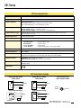
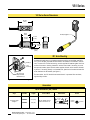
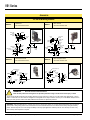
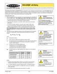
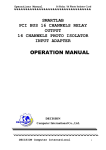
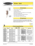
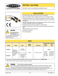
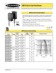
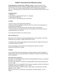
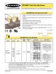
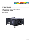
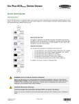
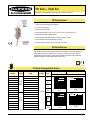
VS1 Series – Visible Red
Miniature convergent/diffuse-mode self-contained sensors
VS1 Series Features
• Totally self-contained miniature sensors
• 10 to 30V dc operation
• Visible red sensing beam
• Choose models with 10 mm (0.4") or 20 mm (0.8") convergent point
• Choose dark or light operate models
• Choose models with NPN (sinking) or PNP (sourcing) output
• 3-wire hookup; output load capacity to 50 mA
• Choice of integral cable or quick-disconnect connector
VS1 Series Overview
VS1 Series miniature self-contained sensors are designed for precision sensing in
small areas previously accessible only to remote or fiber optic models. Typical
applications include mounting inside vibrating feeders and electronic component
handling equipment, where larger sensors will not fit.
Visible red, 630 nm
VS1 Series Convergent Mode Sensors
Models
Range*
Cable
VS1AN5CV10
2 m (6.5') 3-wire
VS1AN5CV10Q
3-Pin Pico-style Pigtail QD
VS1RN5CV10
VS1RN5CV10Q
VS1AP5CV10
VS1AP5CV10Q
VS1RP5CV10
2 m (6.5') 3-wire
VS1RN5CV20Q
VS1AP5CV20
VS1AP5CV20Q
VS1RP5CV20
VS1RP5CV20Q
Printed in USA
PNP/
LO
2 m (6.5') 3-wire
VS1AN5CV20
VS1RN5CV20
NPN/
DO
10 mm 3-Pin Pico-style Pigtail QD
(0.4")
±5 mm 2 m (6.5') 3-wire
3-Pin Pico-style Pigtail QD
3-Pin Pico-style Pigtail QD
Output
Type
NPN/
LO
2 m (6.5') 3-wire
VS1RP5CV10Q
VS1AN5CV20Q
Supply
Voltage
10-30V dc
3-Pin Pico-style Pigtail QD
20 mm 2 m (6.5') 3-wire
(0.8") 3-Pin Pico-style Pigtail QD
±10 mm 2 m (6.5') 3-wire
3-Pin Pico-style Pigtail QD
2 m (6.5') 3-wire
3-Pin Pico-style Pigtail QD
*Range based on 90% white reflectance test card
Excess Gain
Performance based on 90% reflectance white test card
1000
E
X
C
E
S
S
G
A
I
N
100
VS1 Series
3 mm
10 mm Convergent Mode
0.12 in
10 mm Convergent Mode
2 mm
0.08 in
1 mm
0.04 in
0
0
10
1 mm
0.04in
2 mm
0.08 in
0.12 in
3 mm
0
10 mm
.4 in
100 mm
4 in
1000 mm
40 in
4 mm
0.16 in
8 mm
0.31 in
12 mm
0.47 in
16 mm
0.63 in
20 mm
0.79 in
DISTANCE
DISTANCE
1000
NPN/
DO
E
X
C
E
S
S
PNP/
LO
G
A
I
N
PNP/
DO
VS1 Series
1
1 mm
0.04 in
PNP/
DO
NPN/
LO
Beam Pattern
VS1 Series
VS1 Series
100
20 mm Convergent Mode
6 mm
20 mm Convergent Mode
0.24 in
4 mm
0.16 in
2 mm
0.08 in
0
10
0
2 mm
0.08in
4 mm
0.16 in
6 mm
1
1 mm
0.04 in
0.24 in
0
10 mm
.4 in
100 mm
4 in
1000 mm
40 in
10 mm
0.40 in
20 mm
0.80 in
30 mm
1.20 in
40 mm
1.60 in
50 mm
2.00 in
DISTANCE
DISTANCE
P/N 56465F0B
VS1 Series
VS1 Series Specifications
Supply Voltage and Current
10 to 30V dc (10% maximum ripple) at less than 25 mA (exclusive of load)
Supply Protection Circuitry
Protected against reverse polarity and transient voltages
Output Configuration
SPST solid-state switch
Choose NPN (current sinking) or PNP (current sourcing) models
Choose light operate (N.O.) or dark operate (N.C.) models
Output Rating
50 mA maximum
Off-state leakage current: < 1 microamp at 24V dc
On-state saturation voltage: < 0.25V at 10 mA dc; < 0.5V at 50 mA dc
Output Protection Circuitry
Protected against false pulse on power-up and continuous overload or short circuit of outputs
Overload trip point ≥100 mA
Output Response Time
1 millisecond ON and OFF
Repeatability
250 microseconds
Indicators
Two LEDs: Green and Yellow
GREEN ON steadily
GREEN flashing
YELLOW ON steadily
YELLOW flashing
=
=
=
=
power to sensor is ON
output overload
light is sensed
marginal excess gain (1-1.5x) in light condition
Construction
Black ABS/polycarbonate housing with clear acrylic lens
Environmental Rating
IP67; NEMA 6
Connections
2 m (6.5') attached cable: three #28 ga stranded conductors with PE insulation; PVC outer cable jacket;
or 3-pin Pico-style pigtail quick-disconnect fitting. QD cables are ordered separately.
Operating Conditions
Temperature: -20° to +55°C (-4° to +131°F)
Maximum Relative Humidity: 80% at 50°C (non-condensing)
Application Notes
M2 stainless steel mounting hardware included (see “VS1 Mounting”). Optional mounting brackets are
available (page 4).
Certifications
VS1 Series Sensor Hookups
Sensors with NPN Outputs
Cabled Hookup
bu
–
10 to 30 dc
+
bn
bk
Quick-Disconnect Hookup
–
10-30V dc
+
bn
bk
page 2
Load
bn
3-Pin Pico-Style Pin-out
(Cable Connector Shown)
+
10-30V dc
–
bu
bk
Load
bu
Sensors with PNP Outputs
Cabled Hookup
Black Wire
Load
Quick-Disconnect Hookup
bn
Brown Wire
+
10-30V dc
–
bu
bk
Blue Wire
Load
Banner Engineering Corp. • Minneapolis, U.S.A.
www.bannerengineering.com • Tel: 763.544.3164
VS1 Series
VS1 Series Sensor Dimensions
25.7 mm
(1.01")
15 mm
(0.59")
150 mm (6") Pigtail
8.3 mm
(0.33")
4.1 mm
(0.16")
13.5 mm
(0.53")
9.2 mm
(0.36") 11.6 mm
(0.46")
Ø2.2 mm
(0.09")
VS1 Series Mounting
Hex Nut (2)
Lock
Washer (2)
Washer (2)
M2 x 0.4 x 16 mm
Phillips Pan-head
Machine Screw (2)
Included with each sensor is a hardware packet containing two stainless steel M2 x
0.4 x 16 mm Phillips pan-head machine screws, flat washers, lock washers, and hex
nuts. To mount the VS1 Series housing, use the supplied flat washer against the front
surface of the sensor housing, between it and the screw head. If mounting to one of
the optional brackets, place the lock washer against the back of the bracket, followed
by the nut. If mounting directly to a threaded hole, place the lock washer between the
screw head and the flat washer (see figure 1).
For best results, the VS1 should be mounted where it is protected from moisture,
high humidity and dirt.
Figure 1. VS1 Series sensor mounting
Accessories
Quick-Disconnect (QD) Cables
Style
3-pin Pico Style
Straight
Models
Length
PKG3M-2
2 m (6.5')
PKG3M-9
9 m (30')
Banner Engineering Corp. • Minneapolis, U.S.A.
www.bannerengineering.com • Tel: 763.544.3164
For Use With
All VS1 Series sensors
with model suffix “Q”.
Dimensions
34.7 mm
(1.37")
Pinout
M8 x 1
9.6 mm
(0.38")
Black Wire
Blue Wire
Brown Wire
page 3
VS1 Series
Accessories
VS1 Series Mounting Brackets
• Tall bracket
• 300 series stainless steel
SMBVS1T
• Short bracket
• 300 series stainless steel
SMBVS1S
12.5 mm
(0.49")
8x R1.6 mm
(0.06")
2x R6.4 mm
(0.25")
2x 7.6 mm
(0.29")
10.2 mm
(0.40")
4.6 mm
(0.18")
2x R5.6 mm
(0.22")
22.0 mm
(0.87")
13.5 mm
(0.53")
4x R5.6 mm
(0.22")
32.0 mm
(1.26")
13.5 mm
(0.53")
10.8 mm
(0.43")
4x R1.1 mm
(0.44")
6.5 mm
(0.26")
25.0 mm
(0.98")
8x R1.1 mm
(0.44")
1.7 mm
(0.7")
0.9 mm
(0.04")
12.5 mm
(0.49")
12.0 mm
(0.47")
0.9 mm
(0.04")
4x R4 mm (0.15")
5.6 mm
(0.23")
SMBVS1TC
12.5 mm
(0.50")
2x 7.4 mm
(0.29")
8x R1.6 mm
(0.06")
2x R6.4 mm
22.0 mm
(0.25")
(0.87")
2x 1 mm
(0.04")
2x 4.6 mm
(0.18")
10.0 mm
(0.40")
25.0 mm
(0.98")
• Tall compact bracket
• 300 series stainless steel
SMBVS1SC
• Short compact bracket
• 300 series stainless steel
2 x ø2.8 mm (0.11")
4.5 mm
(0.18")
31.0 mm
(1.22")
9.0 mm
(0.35")
!
2x ø2.8mm (0.11)
5.5 mm
(0.22")
3.0 mm
(0.12")
2.3 mm
3.0 mm
(0.09")
(0.12")
4.7 mm
(0.19")
2.3 mm
(0.9")
13.5 mm
(0.53")
0.9 mm
(0.04")
11.0 mm
(0.43")
10.0 mm
(0.39")
WARNING . . .
10.0 mm
(0.39")
13.5 mm
(0.53")
2.0 mm
(0.08")
4.5 mm
3.0 mm
(0.18")
(0.12")
0.9 mm
(0.04")
5.5 mm
(0.22")
2.3 mm (0.9")
9.0 mm
(0.35")
19.5 mm
(0.77")
Not To Be Used for Personnel Protection
Never use this product as a sensing device for personnel protection. Doing so could lead to serious injury or death.
This product does NOT include the self-checking redundant circuitry necessary to allow its use in personnel safety applications. A sensor
failure or malfunction can cause either an energized or de-energized sensor output condition. Consult your current Banner Safety Products
catalog for safety products which meet OSHA, ANSI and IEC standards for personnel protection.
WARRANTY: Banner Engineering Corp. warrants its products to be free from defects for one year. Banner Engineering Corp. will repair or
replace, free of charge, any product of its manufacture found to be defective at the time it is returned to the factory during the warranty
period. This warranty does not cover damage or liability for the improper application of Banner products. This warranty is in lieu of any
other warranty either expressed or implied.
Banner Engineering Corp., 9714 Tenth Ave. No., Minneapolis, MN 55441 • Phone: 763.544.3164 • Fax: 763.544.3213 • E-mail: [email protected]