1
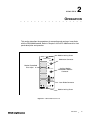
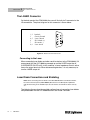
User’s Guide
4000 mA Current Source Module
CSM-39400
ILX Lightwave Corporation · P. O. Box 6310 · Bozeman, MT, U.S.A. 59771 · U.S. & Canada: 1-800-459-9459 · International Inquiries: 406-586-1244 · Fax 406-586-9405
E-mail: [email protected]
www.ilxlightwave.com
70011502_R00_06/03
TA B L E O F C O N T E N T S
TABLE OF CONTENTS
Table of Contents . . . . . . . . . . . . . . . . . . . . . . . . . . . . . . . . . . . . . . . . . . . . . . . . . i
Safety and Warranty Information . . . . . . . . . . . . . . . . . . . . . . . . . . . . . . . . . . . . iii
Safety Information and the Manual . . . . . . . . . . . . . . . . . . . . . . . . . . . . . . . . . iii
General Safety Considerations . . . . . . . . . . . . . . . . . . . . . . . . . . . . . . . . . . . . iii
Safety Symbols. . . . . . . . . . . . . . . . . . . . . . . . . . . . . . . . . . . . . . . . . . . . . . . . . . iv
Safety Marking Symbols . . . . . . . . . . . . . . . . . . . . . . . . . . . . . . . . . . . . . . . . . iv
Warranty . . . . . . . . . . . . . . . . . . . . . . . . . . . . . . . . . . . . . . . . . . . . . . . . . . . . . . . . v
Comments, Suggestions, and Problems . . . . . . . . . . . . . . . . . . . . . . . . . . . .vii
Chapter 1
Introduction and Specifications
Product Overview . . . . . . . . . . . . . . . . . . . . . . . . . . . . . . . . . . . . . . . . . . . . . . . . 1
Specifications . . . . . . . . . . . . . . . . . . . . . . . . . . . . . . . . . . . . . . . . . . . . . . . . . . . 2
Installation . . . . . . . . . . . . . . . . . . . . . . . . . . . . . . . . . . . . . . . . . . . . . . . . . . . . . . 4
Chapter 2
Operation
The LASER Connector . . . . . . . . . . . . . . . . . . . . . . . . . . . . . . . . . . . . . . . . . . . . 6
Connecting to the Laser . . . . . . . . . . . . . . . . . . . . . . . . . . . . . . . . . . . . . . . . . 6
Laser Diode Connections and Shielding . . . . . . . . . . . . . . . . . . . . . . . . . . . . . 6
Photodiode Feedback Connections . . . . . . . . . . . . . . . . . . . . . . . . . . . . . . . . . 9
Grounding Considerations . . . . . . . . . . . . . . . . . . . . . . . . . . . . . . . . . . . . . . . . 10
Modulation Connections . . . . . . . . . . . . . . . . . . . . . . . . . . . . . . . . . . . . . . . . . 10
06_03
CSM-39400
i
TA B L E O F C O N T E N T S
Chapter 3
Calibration
Recommended Equipment . . . . . . . . . . . . . . . . . . . . . . . . . . . . . . . . . . . . . . . . 11
Environmental Conditions . . . . . . . . . . . . . . . . . . . . . . . . . . . . . . . . . . . . . . . . 12
Warm Up . . . . . . . . . . . . . . . . . . . . . . . . . . . . . . . . . . . . . . . . . . . . . . . . . . . . 12
TEC Calibration Procedures . . . . . . . . . . . . . . . . . . . . . . . . . . . . . . . . . . . . . . . 12
Local Operation Current Source Calibration . . . . . . . . . . . . . . . . . . . . . . . . . 13
Remote Operation Current Source Calibration . . . . . . . . . . . . . . . . . . . . . . . 14
Local Operation IPD Current Calibration . . . . . . . . . . . . . . . . . . . . . . . . . . . . 15
Remote Operation IPD Current Calibration . . . . . . . . . . . . . . . . . . . . . . . . . . 17
Local Operation Laser Voltage Measurement Calibration . . . . . . . . . . . . . . 18
Remote Operation Laser Voltage Measurement Calibration . . . . . . . . . . . . 19
ii
CSM-39400
SAFETY AND WARRANTY INFORMATION
The Safety and Warranty Information section provides details about cautionary
symbols used in the manual, safety markings used on the instrument, and
information about the Warranty including Customer Service contact information.
Safety Information and the Manual
Throughout this manual, you will see the words Caution and Warning indicating
potentially dangerous or hazardous situations which, if not avoided, could result in
death, serious or minor injury, or damage to the product. Specifically:
Caution indicates a potentially hazardous situation which can result in minor or
moderate injury or damage to the product or equipment.
Warning indicates a potentially dangerous situation which can result in serious injury or
death.
WARNING
Visible and/or invisible laser radiation. Avoid direct exposure to the beam.
General Safety Considerations
If any of the following conditions exist, or are even suspected, do not use the
instrument until safe operation can be verified by trained service personnel:
• Visible damage
• Severe transport stress
• Prolonged storage under adverse conditions
• Failure to perform intended measurements or functions
If necessary, return the instrument to ILX Lightwave, or authorized local ILX
Lightwave distributor, for service or repair to ensure that safety features are
maintained (see the contact information on page vii).
All instruments returned to ILX Lightwave are required to have a Return
Authorization Number assigned by an official representative of ILX Lightwave
Corporation. See Returning an Instrument on page v for more information.
CSM-39400
iii
SAFETY SYMBOLS
SAFETY SYMBOLS
This section describes the safety symbols and classifications.
Technical specifications including electrical ratings and weight are included within
the manual. See the Table of Contents to locate the specifications and other
product information. The following classifications are standard across all ILX
Lightwave products:
•
Indoor use only
•
Ordinary Protection: This product is NOT protected against the harmful ingress of moisture.
•
Class I Equipment (grounded type)
•
Mains supply voltage fluctuations are not to exceed ±10% of the nominal supply voltage.
•
Pollution Degree II
•
Installation (overvoltage) Category II for transient overvoltages
•
Maximum Relative Humidity: <80% RH, non-condensing
•
Operating temperature range of 0 °C to 40 °C
•
Storage and transportation temperature of –40 °C to 70 °C
•
Maximum altitude: 3000 m (9843 ft.)
•
This equipment is suitable for continuous operation.
Safety Marking Symbols
This section provides a description of the safety marking symbols that appear on
the instrument. These symbols provide information about potentially dangerous
situations which can result in death, injury, or damage to the instrument and other
components.
Caution,
refer to
manual
Earth
ground
Terminal
Alternating
current
Visible and/or
invisible laser
radiation
Caution, risk
of electric
shock
Protective
Conductor
Terminal
Caution, hot
surface
Frame or
chassis
Terminal
On: In position of a bistable push control.
The slash (I) only denotes that mains are on.
or
(I)
iv
CSM-39400
Off: Out position of a bistable push control.
The circle (O) only denotes that mains are off.
or
(O)
WA R R A N T Y
WARRANTY
ILX LIGHTWAVE CORPORATION warrants this instrument to be free from
defects in material and workmanship for a period of one year from date of
shipment. During the warranty period, ILX will repair or replace the unit, at our
option, without charge.
Limitations
This warranty does not apply to fuses, lamps, defects caused by abuse,
modifications, or to use of the product for which it was not intended.
This warranty is in lieu of all other warranties, expressed or implied, including any
implied warranty of merchantability or fitness for any particular purpose. ILX
Lightwave Corporation shall not be liable for any incidental, special, or
consequential damages.
If a problem occurs, please contact ILX Lightwave Corporation with the
instrument's serial number, and thoroughly describe the nature of the problem.
Returning an Instrument
If an instrument is to be shipped to ILX Lightwave for repair or service, be sure to:
1
Obtain a Return Authorization number (RA) from ILX Customer Service.
2
Attach a tag to the instrument identifying the owner and indicating the required service or
repair. Include the instrument serial number from the rear panel of the instrument.
3
Attach the anti-static protective caps that were shipped with the instrument and place the
instrument in a protective anti-static bag.
4
Place the instrument in the original packing container with at least 3 inches (7.5 cm) of
compressible packaging material. Shipping damage is not covered by this warranty.
5
Secure the packing box with fiber reinforced strapping tape or metal bands.
6
Send the instrument, transportation pre-paid, to ILX Lightwave. Clearly write the return
authorization number on the outside of the box and on the shipping paperwork. ILX
Lightwave recommends you insure the shipment.
If the original shipping container is not available, place your instrument in a
container with at least 3 inches (7.5 cm) of compressible packaging material on all
sides.
Repairs are made and the instrument returned transportation pre-paid. Repairs
are warranted for the remainder of the original warranty or for 90 days, whichever
is greater.
06_03
CSM-39400
v
WA R R A N T Y
Claims for Shipping Damage
When you receive the instrument, inspect it immediately for any damage or
shortages on the packing list. If the instrument is damaged, file a claim with the
carrier. The factory will supply you with a quotation for estimated costs of repair.
You must negotiate and settle with the carrier for the amount of damage.
vi
CSM-39400
WA R R A N T Y
Comments, Suggestions, and Problems
To ensure that you get the most out of your ILX Lightwave product, we ask that
you direct any product operation or service related questions or comments to ILX
Lightwave Customer Support. You may contact us in whatever way is most
convenient:
Phone . . . . . . . . . . . . . . . . . . . . . . . . . . . (800) 459-9459 or (406) 586-1244
Fax . . . . . . . . . . . . . . . . . . . . . . . . . . . . . . . . . . . . . . . . . . . . . (406) 586-9405
On the web at: . . . . . . . . . . . . . . . . . . . . . . . . . . . . . . . . . . . . ilx.custhelp.com
Or mail to:
ILX Lightwave Corporation
P. O. Box 6310
Bozeman, Montana, U.S.A 59771
www.ilxlightwave.com
When you contact us, please have the following information:
Model Number:
Serial Number:
End-user Name:
Company:
Phone:
Fax:
Description of what is
connected to the ILX
Lightwave instrument:
Description of the problem:
If ILX Lightwave determines that a return to the factory is necessary, you are
issued a Return Authorization (RA) number. Please mark this number on the
outside of the shipping box.
You or your shipping service are responsible for any shipping damage when
returning the instrument to ILX Lightwave; ILX recommends you insure the
shipment. If the original shipping container is not available, place your instrument
06_03
CSM-39400
vii
WA R R A N T Y
in a container with at least 3 inches (7.5 cm) of compressible packaging material
on all sides.
We look forward to serving you even better in the future!
viii
CSM-39400
CHAPTER
1
INTRODUCTION AND SPECIFICATIONS
Product Overview
The CSM-39400 4000 mA Current Source is a precision current source module
for use in the LDC-3900 Modular Laser Diode Controller. It may be installed in any
of the four bays on the rear of the LDC-3900 (and may be readily interchanged
with any other LDC-3900 module).
Features of the CSM-39400CSM-39400 include:
• 20 W power output (4 A @ 5 V)
• Service-free modularity (calibration information is stored on the CSM-39400)
• Closed-case calibration
• High stability, low noise design
• Flexible setup with LDC-3900 Save / Recall front panel functions
• Photodiode feedback control mode
• Modulation input
CSM-39400
1
CHAPTER
INTRODUCTION AND SPECIFICATIONS
Specifications
1
Specifications
Current Source1
Set Point Accuracy
+8 mA
Set Point Resolution
60 µA
Compliance Voltage (fixed)
5 V maximum
Temperature Coefficient
< 100 ppm / oC
Stability2, for 1 hour
< 10 ppm
Stability3,
< 50 ppm
for 24 hours
Noise and
Ripple4
High Bandwidth Mode
< 20 µA rms
Low Bandwidth Mode
< 20 µA rms
CW Mode (with 320 cable)
< 5 µA rms
Bandwidth
1.
2.
3.
4.
2
CSM-39400
High Bandwidth Mode
DC to 50 KHz
Low Bandwidth Mode
DC to 1 KHz
CW Mode (with 320 cable)
DC to 30 Hz
All values relate to a one hour warm up period.
Over any one hour period, half-scale output.
Over any 24 hour period, half-scale output
Measured from resulting intensity fluctuations of a laser diode, measured optically with a 150 KHz bandwidth photodetector;
measurements made with 1 MHz detector are typically 10% higher. For more information, refer to ILX Noise and Transient Test
Standards publication.
INTRODUCTION AND SPECIFICATIONS
Specifications
CHAPTER
1
Worst Case Transients
Operational5
Power Line
< 5 mA
Induced6
< 20 mA
Photodiode Feedback
Range
5 to 20,000 µA
Output Stability7
+4 µA
Accuracy
+20 µA
Bias Voltage
0 - 5 V reverse bias (+ 10%); adjustable on back panel
Laser Drive Current Display
Output Current Range
0.0 to 4000.0 mA
Output Current Resolution
0.1 mA
o
Output Current Accuracy at 25 C
+4 mA
Photodiode Current Range
0 - 20,000 µA
Photodiode Current Resolution
1 µA
Photodiode Current Accuracy
+4 µA
Responsivity Range
0 - 600.00 µA / mW
Responsivity Resolution
0.01 µA / mW
Optical Power Range
0 - 5000.0 mW
Output Power Resolution
0.1 mW
Type
5-digit green LED
Current Limit Setting
Range
0 - 4000 mA
Resolution
20 mA
Accuracy
+40 mA
Output Connectors
Current Source Output
9-pin, D-sub
Photodiode Input
Coaxial BNC
Analog Modulation Input
Coaxial BNC, instrumentation amplifier input
5. Maximum output current transient resulting from normal operational situations (e.g., power on/off), as well as accidental situations
(e.g., power line plug removal). For more information, refer to ILX Noise and Transient Test Standards publication.
6. Maximum output current transient resulting from a 200 V power line transient spike.
7. Maximum monitor photodiode current drift over any 30 minute period; constant-power mode stability specification assumes zero
drift in detector responsivity.
Our goal is to make the best laser diode instrumentation available anywhere. To
achieve this, we need your ideas and comments on ways we can improve out
products. We invite you to contact us at any time with your suggestions.
06_03
CSM-39400
3
CHAPTER
INTRODUCTION AND SPECIFICATIONS
Installation
1
Installation
This section describes the procedures for installing and removing a CSM-39400
module from the LDC-3900.
Note: The LDC-3900 will power-up in a default state upon detecting any change in the
LDC-3900 system configuration (such as installing a new module). All parameters and
SAVE/RECALL settings will be set to default values, based on the new configuration.
Calibration data is stored in the CSM-39400 module itself, and is never lost due to
reconfiguration of the LDC-3900.
To install the CSM-39400 module into the LDC-3900, follow these steps:
1
Turn the power off on the LDC-3900.
2
Place the CSM-39400 module into an open bay on the back of the LDC-3900 and slide
the module into place. There are tracks at the top and bottom of the bay which guide the
module into place. Push the module into place until the board edge clicks into place with
an audible "pop." This indicates that the module is "locked" into place. Screw the Module
Locking Screws into the back panel to secure the module. It is then ready to be used in
the LDC-3900.
3
Power-up the LDC-3900.
4
After the LDC-3900 has completed its power-up sequence, the (ADJUST) LAS indicator
which corresponds to the newly installed CSM-39400 module should be lit in green,
indicating that the module has been recognized as a LASER current source in its
respective bay.
To remove the CSM-39400 module from the LDC-3900, follow these steps:
4
CSM-39400
1
Turn the power off on the LDC-3900.
2
Unscrew the Module Locking Screws which secure the module to the LDC-3900 back
panel.
3
Grasp the CSM-39400 module by handle which extends from the bottom of the back
panel. Gently, but firmly, pull the module out of the LDC-3900.
4
If the CSM-39400 module is replaced in the LDC-3900 before the LDC-3900 is powered
up again, the LDC-3900 will retain its memory of all parameter settings and
SAVE/RECALL values. However, if the LDC-3900 is powered up and detects a change in
its system configuration, all parameters and SAVE/RECALL information will be lost.
Calibration data is stored in the CSM-39400 module itself, and is never lost due to
reconfiguration of the LDC-3900.
CHAPTER
2
OPERATION
This section describes the procedures for connecting and running a laser diode
with the CSM-39400 module. Refer to Chapter 2 of the LDC-3900 manual for front
panel description and operation.
Module Locking Screw
39400
4000 mA
CURRENT SOURCE
MODULATION
Modulation Connector
400mA/V
Monitor Photodiode
Bias Adjust
PD BIAS
ADJUST
PHOTODIODE
Auxiliary Monitor
Photodiode Feedback
Connector
1,2 INTLK
CHAS GND
3
4,5 LSR CATH
6 PD CATH +
7 PD ANOD 8,9 LSR ANOD
Laser Diode Connector
Module Locking Screw
Figure 2.1 CSM-39400 Back Panel
CSM-39400
5
CHAPTER
2
OPERATION
The LASER Connector
The LASER Connector
On the back panel of the CSM-39400, the user will find a 9-pin D-connector for the
LD connections. The pinout diagram for this connector is shown below.
1, 2
3
4, 5
6
7
8, 9
Interlock
Chassis Ground
Laser Cathode
PD Cathode (+)
PD Anode (-)
Laser Anode
1
2
6
7
3
4
8
9
5
Figure 2.2 Back Panel LD Connector
Connecting to the Laser
When connecting laser diodes and other sensitive devices to the CSM-39400, ILX
recommends that the LDC-3900 be powered up and the LASER output be off
(LASER MODE ON LED unlit). In this condition, a lower impedance shunt is active
across the output terminals. When disconnecting devices, it is only necessary to
turn the LASER output off.
Laser Diode Connections and Shielding
Note: Before connecting the laser diode to the LDC-3900 Modular Laser Diode Controller,
be sure that the front panel (LASER MODE) ON switch is in the OFF position (ON LED
unlit). Before turning on the LASER output, be sure that the current limit has been correctly
set.
The following figures show the possible configurations of connecting laser diodes
and photodiodes with the LDC-3900 Modular Laser Diode Controller.
6
CSM-39400
OPERATION
Laser Diode Connections and Shielding
OUTPUT
CHAPTER
2
3900 Modular Laser Diode Controller
7
+
6
Bias
+
8, 9
4, 5
P. D.
L. D.
3
Earth Ground
Figure 2.3 Common Laser Cathode - Photodiode Cathode
OUTPUT
3900 Modular Laser Diode Controller
7
+
6
Bias
+
8, 9
4, 5
P. D.
L. D.
3
Earth Ground
Figure 2.4 Common Laser Cathode - Photodiode Anode
06_03
CSM-39400
7
CHAPTER
2
OPERATION
Laser Diode Connections and Shielding
OUTPUT
3900 Modular Laser Diode Controller
7
+
6
Bias
+
8, 9
4, 5
P. D.
L. D.
3
Earth Ground
Figure 2.5 Common Laser Anode - Photodiode Cathode
OUTPUT
3900 Modular Laser Diode Controller
7
+
6
Bias
+
8, 9
4, 5
P. D.
L. D.
3
Earth Ground
Figure 2.6 Common Laser Anode - Photodiode Anode
8
CSM-39400
OPERATION
Photodiode Feedback Connections
CHAPTER
2
Note: The cable connections to the laser must be secure enough that they won’t
open-circuit, should they be jostled or bumped. Should an open circuit occur during laser
operation, the LASER output will be turned off (OUTPUT LED unlit) automatically.
Note: Experience indicates that should an open circuit occur during laser operation (while
the LASER is ON), the laser may be damaged by a momentary circuit break-and-remake
before the final circuit break. Therefor, although the CSM-39400 provides a proprietary
debounce protection circuit for the LASER output, secure cabling is important.
Is it recommended that the connections to the LDC-3900 Modular Laser Diode
Controller output be made using twisted wire pairs with an earth-grounded shield.
The output terminals of the unit are left floating relative to earth ground to
suppress AC power-on/power-off transients that may occur through an earthground path. If the output circuit is earth-grounded at some point (such as through
the laser package and mount), the user must be careful to avoid multiple earth
grounds in the circuit. Multiple earth grounds may provide circuit paths that induce
spurious currents in the photodiode feedback circuit and output leads.
Photodiode Feedback Connections
The connector on the back panel of the CSM-39400 contains the current supply
output. The photodiode signal is input at the connector at pins 6 and 7. The
photodiode BNC connection is parallel to the DB9 pins 6 and 7 with the center pin
connected to pin 6 cathode.
The CSM-39400 provides an adjustable reverse bias of 0-5 V for the photodiode.
To set the photodiode bias to 5 volts reverse bias, turn the back panel
PHOTODIODE BIAS ADJUST fully clockwise. To set the photodiode bias to 0
volts reverse bias, turn the back panel PHOTODIODE BIAS ADJUST fully
counter-clockwise.
The photodiode feedback may also be connected via the PHOTODIODE (BNC)
connector, located on the CSM-39400 back panel.
Many laser diode modules contain an internal photodiode that monitors the
back-facet emission of the laser. Usually, this photodiode is internally connected
to either the laser anode or cathode. The previous figures show the recommended
connections and shielding for the various configurations of laser diode modules
and photodiode feedback schemes.
The photodiode and laser inputs on the CSM-39400 are electrically isolated from
ground and each other. So, if a 4-pin connection is made (no common
connections) no additional jumpers are required. The previous figures show the
recommended connections and shielding for 3-pin lasers (where the common
connection is internal to the device). A 4-pin laser should be connected with the
same shielding as shown in Figure 2.2, but the common connection (between the
photodiode and the laser) is optional.
06_03
CSM-39400
9
CHAPTER
2
OPERATION
Grounding Considerations
Grounding Considerations
The LASER outputs of the CSM-39400 are isolated from chassis ground allowing
either output terminal to be grounded at the user's option. Figure 2.3 shows the
proper earth-ground shielding for laser diode/photodiode connections.
Modulation Connections
The MODULATION connector allows a 400 mV/A modulation signal to be applied
to the laser. The modulation port input impedance is 10 kW.
10
CSM-39400
CHAPTER
3
CALIBRATION
The CSM-39400 should be calibrated every 12 months or whenever performance
verification indicates that calibration is necessary.
All calibrations can be done with the case closed. The instrument is calibrated by
changing the internally shored digital calibration constants.
Recommended Equipment
Recommended test equipment for calibrating the CSM-39400 is listed in the table
below. Equipment other than that shown in the table may be used if the
specifications meet or exceed those listed. If the LDC-3900 is equipped with the
Model 1231 GPIB/IEEE-488.2 interface, the user may refer to the calibration
procedures using the GPIB later in this chapter.
Description
Mfg./Model
Specification
DMM
HP 3457A
0.1 µA or 0.1 mV resolution
Resistor
High Power
35 Ω, 5 W, low TCR, for voltage calibration
1 Ω, 50 W, low TCR, for current calibration
Metal Film
High Power
49Ω, and 100 Ω, 1%, 1/4 W
5Ω, 5 W, low TCR
TIL 117
or equivalent, 6-pin
D-sub
9-pin male
IPD Calibration
Resistors
Optical Isolator
Connector
Table 3.1 Recommended Test Equipment
CSM-39400
11
CHAPTER
3
CALIBRATION
Environmental Conditions
Environmental Conditions
Calibrate this instrument under laboratory conditions. ILX recommends calibration
at 23 oC + 1.0 oC. When necessary, however, the LDC-3900 Modular Laser Diode
Controller may be calibrated at its intended use temperature if this is within the
specified operating temperature range of 0 to 50 oC.
Warm Up
The LDC-3900 should be allowed to warm up for at least 1 hour before calibration.
TEC Calibration Procedures
There are four calibration procedures required for the CSM-39400, when using
thermistors.
• Calibration of the constant current source (for both bandwidths)
• Calibration of the laser voltage measurement
• Calibration of the constant light power (IPD) feedback circuits.
The CSM-39400 implements a two-point calibration for the laser current source.
Two currents are applied to a load and the resulting measured currents are fed
back (by the user) to the CSM-39400. The CSM-39400 calibration program uses
the two data points to calculate calibration constants that it will thereafter use to
set current.
If the user has the optional Model 1231 IEEE-488.2/GPIB interface, the procedure
for calibrating the CSM-39400 remotely is later in this chapter.
12
CSM-39400
CALIBRATION
TEC Calibration Procedures
CHAPTER
3
Local Operation Current Source Calibration
The following procedure is for local (front panel) operation. See the following
section for remote calibration of the current source.
1
Select the CSM-39400 to be calibrated by pressing the appropriate (ADJUST) switch. Set
the LASER current limit (LIM I) to full scale, bandwidth as desired, and current set point to
3200 mA (80% of full scale). Measure the exact resistance of the 1 Ω, 50 W resistor and
record it. Calculate the current in the following steps by using Ohm's Law:
I=E/R
-where E is the accurately measured voltage across the resistor, and R is the accurately
measured load resistance. (A 4-point probe resistance measurement is recommended.)
Connect the 1 Ω, 50 W resistor and a calibrated DMM (in parallel) to measure the voltage
across the output (pins 5 and 8).
06_03
2
Turn the (LASER ENABLE) ON switch and press the appropriate OUTPUT switch to turn
the LASER output on. If the LASER output is not on, the LASER I calibration mode cannot
be entered.
3
Enter the LASER I calibration mode by pushing the (GPIB) LOCAL and (LASER
DISPLAY) I switches at the same time. The LASER display will indicate output current in
mA. The LDC-3900 will beep when it is ready to accept a new calibration value.
4
Press and hold in the (PARAMETER) SET switch and turn the ADJUST knob until the
LASER display indicates the same current as calculated from the voltage measurement
(as described in step a).
5
Release the (PARAMETER) SET switch to accept the first calibration value. After the
(LASER DISPLAY) SET switch is released, the LDC-3900 will beep. It will then apply the
second calibration current, approximately one-fourth of the original current.
6
The LDC-3900 will beep when it is ready to accept the second calibration value. When it
does, press and hold in the (PARAMETER) SET switch and turn the ADJUST knob until
the LASER display indicates the same current as calculated from the voltage
measurement (as described in step 1).
7
Release the (PARAMETER) SET switch to accept the second calibration value. After the
(PARAMETER) SET switch is released, the LDC-3900 will calculate the calibration
constants, store them to nonvolatile memory on the CSM-39400, beep, and return to its
former (before calibration) state.
8
Repeat this procedure with the other bandwidth, if desired.
CSM-39400
13
CHAPTER
CALIBRATION
TEC Calibration Procedures
3
Remote Operation Current Source Calibration
The following procedure is for remote (GPIB) operation.
1
Select the CSM-39400 to be calibrated by sending the "LAS:CHAN x" command, where x
is the channel of the CSM-39400. Set the LASER limit to full scale via the "LAS:LIM:I
4000" command, output bandwidth as desired via the "LAS:MODE" command, and
current set point to 80% of full scale via the "LAS:LDI 3200" command. Connect a
calibrated DMM to measure the voltage across the laser output (pins 5 and 8). Calculate
the current in the following steps by using Ohm's Law:
I=E/R
-where E is the accurately measured voltage across the resistor, and R is the accurately
measured load resistance. (A 4-point probe resistance measurement is recommended.)
2
Turn the (LASER ENABLE) ON switch. Enter the "LAS:OUT ON" command to turn the
LASER output on. If the LASER output is not on, the LASER I calibration mode cannot be
entered.
3
Enter the LASER I calibration mode by issuing the "LAS:CAL:LDI" command. The LDC3900 will beep when it is ready to accept the first calibration point.
4
Input the first actual (as calculated in Step a) LASER output current (as an <nrf value>)
via the "LAS:LDI <nrf value>" command.
If this value is to be measured and entered remotely via a GPIB controlled DMM, for
example, the measured value of the current should not be entered until the LDC-3900 is
ready to receive it.
The LDC-3900 will be ready to receive the current value when, after a "LAS:CAL:LDI?"
query is sent, the response from the LDC-3900 is "1".
5
Once the actual I value is entered via the "LAS:LDI" command, the LDC-3900 will beep
and will apply a new current equal to approximately one-fourth (1/4) the previous set
current. The LDC-3900 will be ready to receive the second current value when, after a
"LAS:CAL:LDI?" query is sent, the response from the LDC-3900 is "1".
6
Input the second actual (measured) LASER output current (as an <nrf value>) as in
Step 1.
7
Once the second actual I value is entered via the "LAS:LDI" command, the LDC-3900 will
beep and the new calibration constants will be calculated and stored into non-volatile
memory on the CSM-39400. The "OPC?" query may be used (after the "LAS:LDI" value is
sent) to determine when the calibration is completed.
The operation complete flag (bit 0 of the Standard Event Status Register) may be used to
trigger a service request. This type of interrupt is enabled by setting bit 0 of the Service
Request Enable register (via the *ESE command) and bit 5 of the Service Request
Enable register (via the *SRE command). Service request (SRQ) handling depends on
your GPIB hardware. Refer to your GPIB user's manual for details.
8
14
CSM-39400
Repeat this procedure with the other range, if desired.
CALIBRATION
TEC Calibration Procedures
CHAPTER
3
Local Operation IPD Current Calibration
The following procedure is for calibrating the LASER IPD constant current source.
This procedure calibrates the feedback circuits for constant IPD and constant PPD
modes. When these values are reached and are stable, the user enters the actual
value of the current, as measured by an external DMM. The CSM-39400 then
automatically calibrates the LASER feedback circuits.
This procedure is for local (front panel) operation. See the following section for
remote calibration of the IPD current.
1
Select the CSM-39400 to be calibrated by pressing the appropriate (ADJUST) switch.
With the LASER output off, connect a calibrated ammeter to the PD Anode output of the
CSM-39400, and connect the circuit of Figure 5.1 to the LASER and PD outputs.
If a calibrated ammeter (with 0.1 µA resolution) is not available, place a calibrated DMM
(with 0.1 mV resolution) to measure the voltage across the resistor, R1, as shown in the
figure below. Calculate the current in the following steps by using Ohm's Law:
I=E/R
-where E is the accurately measured voltage across the resistor, and R is the accurately
measured load resistance. (A 4-point probe resistance measurement is recommended.)
2
Set the LASER current limit (LIM I) to 4000 mA. Set the IPD set point to 16,000 µA, and
set the CAL PD parameter to zero. This puts the CSM-39400 into a constant IPD mode.
3
Turn the (LASER ENABLE) ON switch and press the appropriate OUTPUT switch to turn
the LASER output on. If the LASER output is not on, the LASER IPD calibration mode
cannot be entered.
4
Press the (GPIB) LOCAL and (LASER DISPLAY) IPD/PPD switches at the same time to
place the CSM-39400 in its LASER IPD Calibration mode.
After a few seconds the LDC-3900 will beep and the LASER display will show the IPD set
point value.
06_03
CSM-39400
15
CHAPTER
CALIBRATION
TEC Calibration Procedures
3
Interlock - (1)
Interlock - (2)
LD Cathode (5)
LD Anode (9)
R4
1M
PD Cathode + (6)
PD Anode - (7)
9-Pin D-S ub
Am m eter
A
R2
100
R1
49
V
V oltm eter
R3
U1 TIL117
6
1
5
9 V Batt
Ipd Current
2
4
3
CALIB RATIO N C IR CUIT
Figure 3.1 I PD Calibration Circuit
5
After the value on the LASER display is stable (has not changed by more than one digit
for several seconds) the CSM-39400 is ready for the actual IPD value to be entered.
Press and hold in the (PARAMETER) SET switch and turn the ADJUST knob until the
LASER display shows the correct value, as shown on the calibrated ammeter (or the
calculated IPD value from Step 1).
16
CSM-39400
6
Release the (PARAMETER) SET switch to store the first calibration value into non-volatile
memory. It will then expect the second calibration current current, approximately onefourth of the original current.
7
The LDC-3900 will beep when it is ready to accept the second calibration value. When it
does, press and hold in the (PARAMETER) SET switch and turn the ADJUST knob until
the LASER display indicates the same IPDcurrent (as measured directly, or as calculated
in Step 1, from the measured voltage).
8
Release the (PARAMETER) SET switch to accept the second calibration point. After the
(PARAMETER) SET switch is released, the LDC-3900 will calculate the calibration
constants, store them to nonvolatile memory on the CSM-39400, beep, and return to its
former (before calibration) state.
CALIBRATION
TEC Calibration Procedures
CHAPTER
3
Remote Operation IPD Current Calibration
The following procedure is for calibrating the LASER IPD constant current source
over GPIB. This procedure calibrates the feedback circuits for constant IPD and
constant PPD modes. When these values are reached and are stable, the user
enters the actual value of the current, as measured by an external DMM. The
CSM-39400 then automatically calibrates the LASER feedback circuits.
This procedure is for remote (GPIB) operation.
1
With the LASER output off, connect a calibrated ammeter to the PD Anode output of the
CSM-39400, and connect the circuit of Figure 3.1 to the LASER and PD outputs.
If a calibrated ammeter (with 0.1 µA resolution) is not available, place a calibrated DMM
(with 0.1 mV resolution) to measure the voltage across the resistor, R1, as shown in the
previous figure. Calculate the current in the following steps by using Ohm's Law:
I=E/R
-where E is the accurately measured voltage across the resistor, and R is the accurately
measured load resistance. (A 4-point probe resistance measurement is recommended.)
2
Select the CSM-39400 to be calibrated by sending the "LAS:CHAN x" command, where x
is the channel of the CSM-39400. Set the LASER current limit via the "LAS:LIM:I 4000"
command. Set the IPD set point to 16,000 µA via the "LAS:MDI 16000" command. Set the
CAL PD parameter to zero via the "LAS:CALMD 0" command. This puts the CSM-39400
into a constant IPD (MDI) mode.
3
Turn the (LASER ENABLE) ON switch. Enter the "LAS:OUT ON" command to turn the
LASER output on. If the LASER output is not on, the LASER IPD calibration mode cannot
be entered.
4
Enter the "LAS:CAL:MDI" command to place the CSM-39400 in its LASER Current
Calibration mode.
5
After a few seconds, the LDC-3900 will be ready for the actual IPD current to be entered
via the "LAS:MDI" command. The measured value of the current should not be entered
until the LDC-3900 is ready to receive it. The LDC-3900 will beep when it is ready to
accept a new calibration value.
The LDC-3900 will be ready to receive the IPD value when, after a "LAS:CAL:MDI?" query
is sent, the response from the LDC-3900 is "1".
06_03
6
Once the actual I value is entered via the "LAS:MDI" command, the LDC-3900 will beep
and the new calibration value will be stored into non-volatile memory. It will then set the
output to approximately one-fourth of the original current and expect the second
calibration value. The LDC-3900 will be ready to receive the second IPD value when, after
a "LAS:CAL:MDI?" query is sent, the response from the LDC-3900 is "1".
7
Input the second actual (measured) IPD (as an <nrf value>) as in Step 4.
8
Once the second actual monitor diode current value is entered via the "LAS:MDI"
command, the LDC-3900 will beep and the new calibration constants will be calculated
and stored into non-volatile memory in the CSM-3900. The "OPC?" query may be used
(after the "LAS:MDI" value is sent) to determine when the calibration is completed.
CSM-39400
17
CHAPTER
CALIBRATION
TEC Calibration Procedures
3
The operation complete flag (bit 0 of the Standard Event Status Register) may be used to
trigger a service request. This type of interrupt is enabled by setting bit 0 of the Service
Request Enable register (via the *ESE command) and bit 5 of the Service Request
Enable register (via the *SRE command). Service request (SRQ) handling depends on
your GPIB hardware. Refer to your GPIB user's manual for details.
Local Operation Laser Voltage Measurement Calibration
The following procedure is for calibrating the LASER voltage measurement via the
front panel. See the following section for remote (GPIB) calibration of the voltage
measurement.
1
With the LASER output off, connect a calibrated voltmeter, in parallel with a 35 Ω, 5 Watt,
low temperature coefficient resistor, to the LASER output of the CSM-39400 (pins 5 and
8).
2
Select the CSM-39400 to be calibrated by pressing the appropriate (ADJUST) switch. Set
the LASER current limit (LIM I) to 200 mA. Set the LASER I set point to 120 mA.
3
Turn the (LASER ENABLE) ON switch and press the appropriate OUTPUT switch to turn
the LASER output on. If the LASER output is not on, the LASER voltage calibration mode
cannot be entered.
4
Press the (GPIB) LOCAL and (LASER DISPLAY) V switches at the same time to place
the CSM-39400 in its LASER Voltage Calibration mode.
5
After a few seconds, the LDC-3900 will beep when it is ready to accept a new calibration
value. Press and hold in the (PARAMETER) SET switch and turn the ADJUST knob to
enter the LASER voltage measurement value which appears on the DMM. Release the
(PARAMETER) SET switch to enter the value.
Once the actual voltage value is entered, the LDC-3900 will beep. It will then expect the
second calibration voltage point, approximately one-fourth of the original voltage.
18
CSM-39400
6
Input the second actual (measured) LASER voltage (as an <nrf value>) as in Step 5.
7
Once the second actual voltage value is entered, the LDC-3900 will beep and the new
calibration constants will be calculated and stored into non-volatile memory on the
CSM-39400.
CALIBRATION
TEC Calibration Procedures
CHAPTER
3
Remote Operation Laser Voltage Measurement Calibration
The following procedure is for calibrating the LASER voltage measurement via
GPIB.
1
With the LASER output off, connect a calibrated voltmeter, in parallel with a 35 Ω, 5 Watt,
low temperature coefficient resistor, to the LASER output of the CSM-39400 (pins 5 and
8).
2
Select the CSM-39400 to be calibrated by sending the appropriate "LAS:CHAN x"
command, where x is the channel number of the CSM-39400. Set the LASER current limit
via the "LAS:LIM:I 200". Set the I set point via the "LAS:LDI 120" command.
3
Turn the (LASER ENABLE) ON switch. Enter the "LAS:OUT ON" command to turn the
LASER output on. If the LASER output is not on, the LASER voltage calibration mode
cannot be entered.
4
Enter the "LAS:CAL:LDV" command to place the CSM-39400 in its LASER Voltage
Calibration mode.
5
After a few seconds, the LDC-3900 will be ready for the actual laser voltage to be entered
via the "LAS:LDV" command. The measured value of the voltage should not be entered
until the LDC-3900 is ready to receive it.
The LDC-3900 will be ready to receive the voltage value when, after a "LAS:CAL:LDV?"
query is sent, the response from the LDC-3900 is "1".
6
Once the actual voltage value is entered via the "LAS:LDV" command, the LDC-3900 will
beep. It will then set the output to approximately one-fourth of the original voltage and
expect the second calibration value to be entered. The LDC-3900 will be ready to receive
the second voltage value when, after a "LAS:CAL:LDV?" query is sent, the response from
the LDC-3900 is "1".
7
Input the second actual (measured) LASER voltage (as an <nrf value>) as in Step 5.
8
Once the second actual voltage value is entered via the "LAS:LDV" command, the LDC3900 will beep and the new calibration constants will be calculated and stored into nonvolatile memory on the CSM-39400.
The operation complete flag (bit 0 of the Standard Event Status Register) may be used to
trigger a service request. This type of interrupt is enabled by setting bit 0 of the Service
Request Enable register (via the *ESE command) and bit 5 of the Service Request
Enable register (via the *SRE command). Service request (SRQ) handling depends on
your GPIB hardware. Refer to your GPIB user's manual for details.
06_03
CSM-39400
19
CHAPTER
20
CSM-39400
3
CALIBRATION
TEC Calibration Procedures