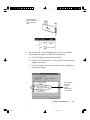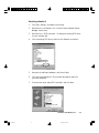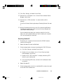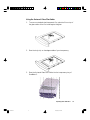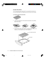
1
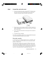
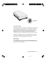
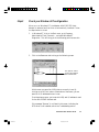
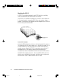
1505AE SCSI ScanMaker 5 Flatbed Color Scanner User's Manual Untitled-7 1 10/19/00, 3:21 PM Copyright 1997 by Microtek International, Inc. All rights reserved. Trademarks Microtek and ScanMaker are trademarks of Microtek International, Inc. IBM PC is the trademark of International Business Machines Corporation. Windows and MS-DOS are trademarks of Microsoft Corporation. Other product or company names are trademarks or registered trademarks of their respective holders. Important Documents that you scan may be protected under copyright law. The unauthorized use of such documents could be a violation of the rights of the copyright holder. Microtek bears no responsibility for the unauthorized use of copyrighted materials. Doc. No. I49-001797 First Edition December 1997 Microtek Lab, Inc. 3715 Doolittle Drive Redondo Beach, CA 90278-1226 Main: (310) 297-5000 Sales: 800-654-4160 Technical Support: (310) 297-5151 FAX: (310) 297-5050 BBS: (310) 297-5102 AutoTech fax back system: (310) 297-5101 World Wide Web site: http:// www.microtekusa.com Microtek International, Inc. 6, Industry East Road 3 Science Based Industrial Park Hsinchu, 30077, Taiwan, R.O.C. TEL: 886-3-5772155 FAX: 886-3-5772598 Microtek Europe B.V. Max Euwelaan 68 NL-3062 MA Rotterdam The Netherlands TEL: 31-10-2425688 FAX: 31-10-2425699 ii Untitled-7 2 10/19/00, 3:21 PM Federal Communications Commission (FCC) Statement This equipment has been tested and found to comply with the limits for a Class B digital device, pursuant to Part 15 of the FCC Rules. These limits are designed to provide reasonable protection against harmful interference in a residential installation. This equipment generates, uses and can radiate radio frequency energy and, if not installed and used in accordance with the instructions, may cause harmful interference to radio communications. However, there is no guarantee that interference will not occur in a particular installation. If this equipment does cause harmful interference to radio or television reception, which can be determined by turning the equipment off and on, the user is encouraged to try to correct the interference by one or more of the following measures: • Reorient/relocate the receiving antenna. • Increase the separation between the equipment and receiver. • Connect the equipment into an outlet on a circuit different from that to which the receiver is connected. • Consult the dealer or an experienced radio/TV technician for help. Note: Shielded interface cable with ferrite core installed on scanner connector end must be used with this equipment. Trade Name Model Name ScanMaker 5 MRS-2000TP CAUTION Changes or modifications not expressly approved by the manufacturer responsible for compliance could void the user's authority to operate the equipment. iii Untitled-7 3 10/19/00, 3:21 PM iv Untitled-7 4 10/19/00, 3:21 PM Contents 1 Introduction 1-1 Built-in SCSI Interface and ADF .................................................. 1-2 Scan Mode ................................................................................ 1-2 Error Detection and Self-test ....................................................... 1-3 Application Programs ................................................................. 1-3 Specifications ............................................................................ 1-4 2 Before You Begin 2-1 Unpack your Scanner ................................................................. 2-1 Checking the Voltage ................................................................. 2-3 Releasing the Carriage ................................................................ 2-3 3 Installation under Windows 95 3-1 Requirements ............................................................................ 3-1 Installation Steps ....................................................................... 3-1 Step 1 Unpack and unlock your scanner .............................. 3-2 Step 2 Install the interface card in your computer .................. 3-2 Step 3 Check interface card status ....................................... 3-3 Step 4 Install scanner software ............................................ 3-4 Step 5 Connect the card and scanner ................................... 3-4 Daisy-chain connection ............................................ 3-5 Terminators ............................................................ 3-5 Checking the SCSI ID .............................................. 3-6 Set the SCSI ID number ........................................... 3-6 SCSI Conflicts ......................................................... 3-7 Step 7 Check scanner status ............................................... 3-8 Step 8 Test your scanner ..................................................... 3-9 Step 9 Troubleshooting .................................................... 3-11 Resolving situation A .............................................. 3-11 Resolving situation B .............................................. 3-11 Resolving situation C ............................................. 3-17 Resolving situation D ............................................. 3-19 v Untitled-7 5 10/19/00, 3:21 PM 4 Installation under Windows 3.1x 4-1 Requirements ............................................................................ 4-1 Installation Steps ....................................................................... 4-1 Step 1 Unpack and unlock your scanner .............................. 4-2 Step 2 Install the interface card in your computer .................. 4-2 Step 3 Connect the card and scanner ................................... 4-3 Daisy-chain connection ............................................ 4-3 Terminators ............................................................ 4-4 Checking the SCSI ID .............................................. 4-4 Set the SCSI ID number ........................................... 4-5 SCSI Conflicts ......................................................... 4-5 Step 4 Install 1505acfg.exe program .................................... 4-6 Step 5 Install scanner software ............................................ 4-7 Step 6 Test your scanner ..................................................... 4-7 5 Installation under Windows NT 4.0 5-1 Requirements ............................................................................ 5-1 Installation Steps ....................................................................... 5-1 Step 1 Unpack and unlock your scanner .............................. 5-2 Step 2 Install the interface card in your computer .................. 5-2 Step 3 Check your Windows NT configuration ..................... 5-3 Step 4 Install scanner software ............................................ 5-4 Step 5 Connect the scanner and computer ........................... 5-4 Daisy-chain connection ............................................ 5-5 Terminators ............................................................ 5-5 Checking the SCSI ID .............................................. 5-6 Set the SCSI ID number ........................................... 5-6 SCSI Conflicts ......................................................... 5-7 Step 6 Test your scanner ..................................................... 5-8 Troubleshooting ................................................................ 5-10 Resolving situation A .............................................. 5-10 Resolving situation B .............................................. 5-10 Resolving situation C ............................................. 5-12 vi Untitled-7 6 10/19/00, 3:21 PM 6 Installation under Macintosh 6-1 Requirements ............................................................................ 6-1 Installation Steps ....................................................................... 6-1 Step 1 Unpack and unlock your scanner .............................. 6-2 Step 2 Connect the scanner and computer ........................... 6-2 Daisy-chain connection ............................................ 6-3 Terminators ............................................................ 6-3 Checking the SCSI ID .............................................. 6-4 Set the SCSI ID number ........................................... 6-4 SCSI Conflicts ......................................................... 6-5 Step 3 Install scanner software ............................................ 6-5 7 Operating the ScanMaker 5 7-1 Performing the Power-on Test ..................................................... 7-1 Positioning a Document ............................................................. 7-2 A. Placing reflective materials .............................................. 7-2 B. Scanning Thick Documents ............................................ 7-3 C. Placing transparent film .................................................. 7-4 Using the Universal Glass Film Holder ............................. 7-5 Using the Main Holder ................................................... 7-6 a) Using the 35mm Batch Slide Holder ...................... 7-6 b) Using the 35mm Filmstrip Holder ........................ 7-7 c) Using the 6 x 9 cm Batch Film Holder ................... 7-8 d) Using the 4" x 5" Batch Film Holder ..................... 7-9 Miscellaneous ......................................................................... 7-10 Returning your scanner for repairs ....................................... 7-10 Locking the carriage ........................................................... 7-11 Lamp Replacement ............................................................ 7-12 A Technical Support A-1 vii Untitled-7 7 10/19/00, 3:21 PM viii Untitled-7 8 10/19/00, 3:21 PM 1 Introduction An image scanner is a device that captures and converts illustrations, graphics, photographs, or text into electronic files that can be edited or enhanced and then incorporated in printed documents or multimedia presentations. The single-pass, 36-bit, high-resolution ScanMaker 5 has been specifically designed and engineered for the discriminating scanner user, who demands rich, detailed images suitable for any prepress or multimedia need. The ScanMaker 5 color flatbed scanner scans reflective originals, but also features internal media trays for scanning positive or negative film in a variety of industry-standard formats. The ScanMaker 5 includes 36-bit throughput capability for delivering images with more image data than 30- or 24- bit scanners are capable of capturing, superior optics and hardware components, as well as Microtek's award-winning ScanWizard scanner controller software. Introduction Untitled-3 1 10/19/00, 4:58 PM 1-1 Built-in SCSI Interface and ADF The ScanMaker 5 features a built-in SCSI interface with the following distinctions: • For Windows-based computers, the ScanMaker 5 includes a SCSI interface card and a SCSI T-cable to connect the scanner to the computer. • For Macintosh computers, the ScanMaker 5 includes a SCSI Tcable to connect the scanner to the computer (no interface card is necessary). SCSI Interface ADF Interface • For large quantify of document scanning, you may need to purchase optional Automatic Document Feeder (ADF). The ADF interface is a connector available for connection with your ADF. Scan Mode The digitized images that are output from the scanner contain up to 1000 dots per inch of information from the original document. Dots can be represented by a single bit indicating black or white, by a 12bit code indicating any one of 4096 levels of gray, or by a 36-bit code indicating any one of over 68 million colors. 1-2 Untitled-3 ScanMaker 5 Flatbed Color Scanner User's Manual 2 10/19/00, 4:58 PM The ScanMaker 5 flatbed color scanner is capable of performing has these scanning modes: Single-bit mode This mode lets you scan black-and-white material in line art or halftone mode. Line art is solid black and white, while halftone creates the illusion of gray with a pattern of black dots. 8-bit grayscale mode This mode uses eight bits to represent the shading of the original document with up to 256 levels of gray. 12-bit grayscale mode This mode uses twelve bits to represent the shading of the original document with up to 4096 levels of gray. 24-bit color mode This mode reproduces any of 16.7 million colors. 36-bit (12-bit x 3) color mode This mode reproduces any of 68 billion colors. 36-bit color is achieved by using a piece of color CCD in combination with a cold cathode lamp. Error Detection and Self-test The ScanMaker 5 flatbed color scanner features powerful error detection and self-diagnostic functions for maximum operating convenience. Application Programs In your ScanMaker flatbed color scanner package, you will find the appropriate bundled software programs for your documents. Introduction Untitled-3 3 10/19/00, 4:58 PM 1-3 Specifications Media Reflective color or black-and-white originals. Image Sensor Trilinear color CCD with cold cathode lamp. Scanning Modes Single scanning pass; 36-bit color; 12-bit grayscale; 1-bit black and white; 12 builtin halftones. Scanning Area Reflective: 8" x 14" (203 mm x 355 mm); Transparency: 8" x 10" (203 mm x 254 mm) Optical Resolution 1000 dpi (H) x 2000 dpi (V) Interpolated Resolution 8000 dpi (H) x 8000 dpi (V) Image Controls Brightness Settings From -100% to 100% in 1% increments Contrast Settings From - 100% to +100% in 1% increments Exposure Time Selections From 0% to +510% in 3% increments Resolution Settings 1 dpi to 1200 dpi in 1-dpi increments Scanning Speed 10 milliseconds per line for line art, halftone, and gray; 15 milliseconds per line for color (speed measured at 1000 dpi) Scanning times vary greatly, depending on image dimensions, resolution, memory capacity, disk access speed, and display time. Acoustic Noise 1-4 Untitled-3 Operating: ≤ 55 dB(A) in worst condition Standby: ≤ 45 dB(A) ScanMaker 5 Flatbed Color Scanner User's Manual 4 10/19/00, 4:58 PM Interface Dimensions (L x W x H) SCSI interface 24.4" x 15.2" x 7" (620 mm x 386 mm x 177 mm) Weight Net 28.2 lb. (12.8 kg) Voltage AC 100 V to 240 V Power Consumption AC 100 V to 240 V: 1.2 A Max. 47 to 63 Hz; 40 watts Operating Environment Temperature 10° to 40° C (50° to 104° F) Relative Humidity 20% to 85% RH Storage Environment Temperature -10° to 60° C (14° to 140° F) Introduction Untitled-3 5 10/19/00, 4:58 PM 1-5 1-6 Untitled-3 ScanMaker 5 Flatbed Color Scanner User's Manual 6 10/19/00, 4:58 PM 2 Before You Begin This chapter provides information on what you need to do before installing your scanner. You will be doing the following: • Unpacking the scanner • Checking the voltage • Releasing the carriage Unpack your Scanner Open your scanner package and check the components as stated in your packing list. Remove the scanner from the box, and save the box and packing materials in case you need to ship the scanner again. Upon opening the scanner box, you will see a Packing List that lists both hardware and software components of your scanner package, as well as the part numbers for those components. If any component is missing, call Microtek Sales and provide information on the missing component and part number. Please be ready to provide the scanner's serial number and your proof of purchase as well. Keep the Packing List for your reference in case you need to order a component in the future. Fill up the Warranty and Registration card and mail it to Microtek today. Note: If you need to ship back the scanner for any repairs, the scanner must be packed in the original box in which it came. Otherwise, Microtek will not be responsible for any damage that may be sustained during shipping to or from Microtek. You may be charged for a new box. Before You Begin Untitled-4 1 10/19/00, 3:18 PM 2-1 10 1 11 2 12 7 3 13 4 5 8 14 15 6 9 1. ScanMaker 5 Scanner 10. Universal Glass Film Holder 2. SCSI T-cable 11. Main Holder 3. Power Cable 12. 35mm Batch Slide Holder 4. SCSI Terminator (Optional) 13. 35mm Filmstrip Holder 5. Adaptec SCSI 1505AE Interface Card 14. 4" x 5" Batch Film Holder 6. Scanner Software CD-ROM 15. 6 x 9 cm Batch Film Holder 7. ScanWizard Quick Reference Guide 8. Microtek Scanner Installation Guide 9. Warranty Card 2-2 Untitled-4 ScanMaker 5 Flatbed Color Scanner User's Manual 2 10/19/00, 3:18 PM Checking the Voltage The voltage of the scanner is indicated at the back of the scanner near the power switch. Voltage is preset depending on your area, ranging from 100V to 120V (U.S. and Canada), or 100V to 240V (Europe and other parts). In the unlikely event that you receive a scanner with a voltage setting different from the voltage level used in your area, call your dealer to return the scanner. Scanners marked with 100V to 120V will not operate with 220-volt power in Europe or South America. Releasing the Carriage Your scanner has a locking screw to protect the scanner carriage mechanism during shipping. Before you operate the scanner, you need to disengage the locking screw. To release the carriage: 1. With the scanner turned off, turn the scanner on its side to see the locking screw at the bottom. 2. Using a coin or a screwdriver, turn the locking screw counterclockwise to unlock it. When successfully unlocked, the screw will push out a little, nearly even with the bottom of the scanner. You can check the lock's status by pushing on the screw cap. If the screw springs back, the scanner has been unlocked and is ready for scanning. Before You Begin Untitled-4 3 10/19/00, 3:18 PM 2-3 2-4 Untitled-4 ScanMaker 5 Flatbed Color Scanner User's Manual 4 10/19/00, 3:18 PM 3 Installation under Windows 95 This chapter describes the requirements and installation for using your ScanMaker flatbed color scanner under Windows 95. Requirements • 486 DX, Pentium or compatibles with a CD-ROM drive • 16MB RAM • Microsoft Windows 95 • At least 800MB hard disk with 100MB free • VGA color monitor; 24-bit color display card Installation Steps To install, you will be doing the following: 1. Unpack and unlock your scanner 2. Install the interface card in your computer 3. Check interface card status 4. Install scanner software 5. Connect the card and scanner 6. Check scanner status 7. Test your scanner 8. Troubleshooting Installation under Windows 95 Untitled-4 1 10/19/00, 5:00 PM 3-1 Step 1 Unpack and unlock your scanner Open your scanner package, check the components as stated in your packing list, and unlock your scanner carriage (for details, refer to Chapter 2). Step 2 Install the interface card in your computer Before installing the interface card supplied with your scanner, make sure you turn off your computer and peripherals. Then follow the steps below: 1. Before handling the interface card, touch a metal frame (such as your computer casing) to discharge any static electricity build up in your body. 2. Shut down your computer and unplug the power cord. Next, remove the cover from your computer (see your owner's manual for instructions on how to do this). 3. Look for an empty ISA slot in your computer, then insert the interface card. To insert, remove the screw that holds the bracket, then remove the bracket itself. When you insert the card, make sure the card is seated all the way into the slot, especially the back, then put the screw back into the bracket. Be aware that the back of the card may pop out a little when you tighten the screw on the card, so be sure that the back of the card (as well as the front) is in all the way, held in place by the card slot, to ensure a proper connection. This is important, as an improper card connection will make you unable to use your scanner, and you will then have to remove the computer case and restart the card all over again. 4. Replace the cove of the computer, then plug the power cord back in place. 3-2 Untitled-4 ScanMaker 5 Flatbed Color Scanner User's Manual 2 10/19/00, 5:00 PM Step 3 Check interface card status When you run Windows 95, the Adaptec AVA-1505 SCSI Host Adapter is detected and the driver is automatically installed. Follow steps below to check. 1. Turn on your computer, click Start , Settings , and then select Control Panel . 2. Double-click on the System icon in Control Panel, and select Device Manager from the top. 3. Double-click on SCSI controllers to display the message below. The result of the check “Adaptec AVA-1505 SCSI Host Adapter” is displayed here. The message “Adaptec AVA-1505 SCSI Host Adapter” displays indicates that the driver is installed and the card work properly. If a conflict exists, either of the following will occur: • a yellow exclamation mark appears next to the phrase: Adaptec AVA-1505 SCSI Host Adapter - or • nothing is listed under “SCSI Controllers”. In either case, refer to the Troubleshooting section. Installation under Windows 95 Untitled-4 3 10/19/00, 5:00 PM 3-3 Step 4 Install scanner software The software installation procedures is continually updated to reflect the most current software bundles for your scanner. For the latest information on software installation, please refer to a document called Microtek Scanner Installation Guide, which is printed separately and is included with your scanner package. Step 5 Connect the card and scanner Before connecting the scanner to your computer, make sure the scanner driver (ScanWizard) is installed. Take the following steps to connect. 1. Shut down your computer. 2. Connect the card and the scanner, using the SCSI T-cable that came with your scanner for this purpose. Make sure your scanner and computer are turned off when you perform the connection. SCSI T-cable 3. Plug the power cord to the power connector at the back panel of the scanner, and plug the other end of the power cord to your AC power source at wall outlet. 4. Turn on your scanner and wait for all the light on the front panel to stop blinking. 5. Then power up your computer. When running Windows, Always turn on the scanner before the computer. If you don't Windows will not be able to “see” your scanner. 3-4 Untitled-4 ScanMaker 5 Flatbed Color Scanner User's Manual 4 10/19/00, 5:00 PM Daisy-chain connection If you have one or more SCSI peripherals (such as a CD-ROM, tape drive or optical disk), the SCSI devices can be connected one after another in a daisy chain. Take note that in a daisy-chain connection, different drivers come into play and complicated configurations may result. If you are not familiar with the procedure for daisy chaining, consult a technician on how to do this. Microtek bears no responsibility for damages that may occur to peripherals due to inexperienced handling. Terminators You probably won't need a terminator for your installation, but because of varying SCSI standards, there is no way to predict with absolute certainty whether or not you need one. You will need a terminator in the following instances: • If you get odd symptoms after hooking up your PC and scanner (such as communication errors during scanning, in which your scanner can't be “seen” by your computer), or if your PC refuses to boot up properly after you installed the scanner. • If you are hooking up your PC in a daisy chain to two or more SCSI devices (such as your scanner and a CD-ROM drive). In this case, the terminator should be on the last SCSI device in the daisy chain. Installation under Windows 95 Untitled-4 5 10/19/00, 5:00 PM 3-5 Checking the SCSI ID A SCSI ID is a number assigned to each SCSI device in your daisy chain to differentiate the devices from one another. The SCSI ID for ScanMaker flatbed color scanners is set at default to 6. You won't need to change the SCSI ID on your scanner unless another SCSI device on your system (such as a tape drive or CD-ROM drive) is using the same number. SCSI default ID number Set the SCSI ID number Locate the SCSI ID switch, which is on the back panel of the scanner. To change the SCSI ID, use a small pin (or the end of a paper clip, or a small screwdriver) and press either of the small black openings located above or below the SCSI ID. Pressing the upper opening “-” decreases the SCSI ID number; pressing the lower opening “+” increases the number. See additional notes at the end of this section. Valid SCSI ID numbers are 0 to 6. Do not use SCSI ID #7, which is used to carry a self-test for the scanner and make the carriage move back and forth. SCSI ID #8 and #9 are also not used. 3-6 Untitled-4 ScanMaker 5 Flatbed Color Scanner User's Manual 6 10/19/00, 5:00 PM SCSI Conflicts Conflict between your scanner and other SCSI hardware devices in your system can happen, owing to the varying SCSI standards that are used for SCSI peripherals today. If you are having SCSI conflicts: • Change the order of your SCSI devices in the daisy chain. Some SCSI conflicts may be resolved by moving the scanner and other SCSI peripherals to different positions in the chain. • Check the SCSI ID number of your SCSI devices, and make sure that no two devices have the same ID you can use, the SCSI check feature in the ScanWizard scanner controller to tell you what the IDs are of the devices in your SCSI chain. For more details, refer to the “Get SCSI Chain Info” section in the Reference chapter. • Use a shorter cable (4 feet or shorter) for each segment of the chain. The use of longer-than-authorized cables accounts for more than 50% of SCSI-related problems. • Make sure that none of the middle SCSI devices are terminated, and make sure that only the last SCSI device is terminated. • Always terminate the last device in your SCSI chain with an external terminator and not an internal terminator. • If you use a SCSI interface card other than the card bundled with your scanner allows for synchronous communication, disable it. You can normally do this by booting your computer and pressing a special key sequence to get to the setup menu for your SCSI interface. For more information, call the manufacturer of your other SCSI card. Installation under Windows 95 Untitled-4 7 10/19/00, 5:00 PM 3-7 Step 7 Check scanner status When running Windows, Always turn on the scanner before the computer. If you don't Windows will not be able to “see” your scanner. 1. Click Start , Settings , and then select Control Panel . 2. Double-click on the System icon in Control Panel, and select Device Manager from the top. 3. The screen that appears displays the message “MICROTEK Scanners”. Double-click on SCSI controllers , the scanner model you connected shows under it. The message “MICROTEK Scanners” indicates that the scanner is installed. If your system can not find your scanner, maybe SCSI conflict happens between your scanner and other SCSI device. To resolve the conflict, refer to Troubleshooting in this chapter. 3-8 Untitled-4 ScanMaker 5 Flatbed Color Scanner User's Manual 8 10/19/00, 5:00 PM Step 8 Test your scanner 1. Restart Windows 95. 2. Click Start, Program , Microtek ScanWizard for Windows 95 , and then select Scanner Test 3. When Scanner Test started up successfully, the screen below appears. The Scanner Model shows the scanner connected to your PC and the scanner's SCSI ID. The “Sparrow” means you are using Adaptec SCSI interface card. The Flatbed button. The SCSI Check acts as a SCSI probe to verify the location of your scanner and check the scanner ID. The Reconfigure Equipment allows the system to update its own internal reference file and is useful when you have changed your setup or reconfigured your system. Installation under Windows 95 Untitled-4 9 10/19/00, 5:00 PM 3-9 4. Place your document face down on the scanner glass. The center top edge of the document should be at the “0” position of the top ruler guide running along the top of the scanner. “0” mark is in the middle. 5. Click the Flatbed button on the Microtek ScanTest program screen. A grayscale preview of your image will be displayed in the Microtek ScanTest window. This indicates the Scanner Test was successful and that the scanner is now ready to be used. 6. Close and exit the Microtek Scanner Test program. 3-10 Untitled-4 ScanMaker 5 Flatbed Color Scanner User's Manual 10 10/19/00, 5:00 PM Step 9 Troubleshooting After installing the interface card in your computer and connecting the scanner, you may find yourself unable to use the scanner. This is usually due to any of the situations described below: Situation A Your interface card is not properly seated in the ISA card slot on your computer. Situation B Your interface card conflicts with another device. Situation C The AVA-1505AE SCSI driver is not appropriately installed in your computer. Situation D Windows 95 does not work on Windows 95 Normal Mode. See details below for resolving the individual situations. Resolving situation A Make sure the card is seated all the way in and secured into the ISA card slot. Resolving situation B 1. Click Start , Settings , and select Control Panel . 2. Double-click on the System icon in Control Panel and select Device Manager from the top. 3. Double-click on “SCSI controllers ” to display the dialog box below. A yellow exclamation mark appears next to the message “Adaptec AVA-1505 SCSI Host Adapter” Installation under Windows 95 Untitled-4 11 10/19/00, 5:00 PM 3-11 4. Click on the Adaptec AVA-1505 SCSI Host Adapter click Properties . option, and then 5. Select Resources from the top. The dialog box gives you information about the Interrupt Request (IRQ) and Input/Output (I/O) address settings, including whether a conflict happens. 6. If a conflict exists in Input/Output option, then click Change Setting . Use the Arrow Down button to select a different range. Click the Arrow Down button to select IRQ. Conflict status You may need to change the Input/Output (I/O) address to Off (340h). 7. Click OK to save the modifications. If you’re asked to shut down your computer, select No, then click Close . Your will be asked whether you wish to restart your computer. Click No to instead shut down computer and turn the power off. Change the I/O address settings on the card to match the settings in Windows you selected. a) Take the interface card out of the computer. b) Remove the shunt from J3 to match setting you given in step 6. c) Put the card back inside your computer. d) Reconnect your scanner, and start your scanner and computer. 3-12 Untitled-4 ScanMaker 5 Flatbed Color Scanner User's Manual 12 10/19/00, 5:00 PM J3 is set to ON by default, indicating the I/O port address is 140h. 8. If a conflict exists in Interrupt/Request option, look for an available IRQ number to be used for the AVA-1505 interface card. a) Click Start , Settings , and select Control Panel . b) Double-click the System icon in Control Panel, then select Device Manager from the top. c) Click on Computer and click the Properties button to display the occupied IRQ settings. In this example, number 10 does not appear, indicating IRQ 10 is available. Installation under Windows 95 Untitled-4 13 10/19/00, 5:00 PM 3-13 Take note of the following: • If 10 does not appear in your dialog box, this means it is available. • If 10 appears in your dialog box, this means it is not available and that your should use another IRQ from 9 to 12. • If all IRQs from 9 to 12 are taken, you need to contact your dealer or computer manufacturer to help on how to free up an IRQ in this range. 9. Disable the “ISA Plug and Play mode ”. a) Insert Microtek CD-ROM into your CD-ROM drive, and run the 1505acfg.exe program in the SCSIUTL directory. Running this program under DOS, you can get a screen like the following: b) Select Configure/View Host Adapter Settings and display the screen below. 3-14 Untitled-4 ScanMaker 5 Flatbed Color Scanner User's Manual 14 10/19/00, 5:00 PM press Enter to c) Use the Up/Down arrow keys to select the “Advanced Configuration Options ” and press Enter. Press Enter, then choose to disable the “ISA Plug and Play mode ”. Set the “Host Adapter Interrupt (IRQ) channel ” manually to match an available IRQ setting in Windows 95. d) Press Esc until you get a Save Changes Y/N prompt, select Yes to save changes, and press Enter to restart your computer. 10. Restart Windows 95. 11. Add new hardware and install correct driver. a) Click Start , Settings , and select Control Panel . b) Double-click Add New Hardware in the Control Panel . c) Click Next and select No for “Do you want Windows to search for your new hardware?”. d) From the next menu, select SCSI controllers and click Next . Installation under Windows 95 Untitled-4 15 10/19/00, 5:00 PM 3-15 e) Select Adaptec on the left and “Adaptec AVA-1505 SCSI Host Adapter ” on the right. Click Next . f) When the next menu appears, you should make a note of the Input/Output (I/O) range setting, as well as Interrupt Request (IRQ) number that Windows recommends you. Write this message on a piece of paper for handy reference. g) When the “Add New Hardware Wizard” dialog box appears, click Finish . h) Continue until the installation is completed. Windows 95 will then ask if you want to shut down your computer. Select No. 12. You may or may not need to change IRQ number. You will only need to change the IRQ number if IRQ number that Windows recommends does not match the settings given in step 9, section c). (see page 7) 3-16 Untitled-4 ScanMaker 5 Flatbed Color Scanner User's Manual 16 10/19/00, 5:00 PM Resolving situation C 1. Click Start , Settings , and select Control Panel . 2. Double-click on the System icon in Control Panel and select Device Manager from the top. 3. Double-click on “SCSI controllers ” to display the existing SCSI driver for your interface card. 4. Click the existing SCSI driver, and then click Remove to remove it. 5. Double-click Add New Hardware in the Control Panel . 6. Click Next and select No for “Do you want Windows to search for your new hardware?”. 7. From the next menu, select SCSI controllers and click Next . Installation under Windows 95 Untitled-4 17 10/19/00, 5:00 PM 3-17 8. Select Adaptec on the left and “Adaptec AVA-1505 SCSI Host Adapter ” on the right. Click Next . 9. In the next menu, make a note of the Input/Output (I/O) range setting, as well as Interrupt Request (IRQ) number that Windows is suggesting you should use. 10. When the “Add New Hardware Wizard” dialog box appears, click Finish . 11. Continue until the installation is completed. Windows 95 will then ask if you want to shut down your computer. Select No. 3-18 Untitled-4 ScanMaker 5 Flatbed Color Scanner User's Manual 18 10/19/00, 5:00 PM 12. Click Start , Settings , and select Control Panel . 13. Double-click on the System icon in Control Panel and select Device Manager from the top. 14. Double-click on “SCSI controllers ” to check whether conflict happens. If conflict still exists, following the steps of Resolving Situation B to reset it. 15. When all the settings are correct, click OK to save the modifications. The dialog box should now show the correct Interrupt Request and Input/Output address settings. If you’re asked to shut down your computer, select No, then click Close . Your will be asked whether you wish to restart your computer. Click Yes and restart your computer. Resolving situation D 1. Shut down your computer and remove the AVA-1505AE interface card from the computer. 2. Restart Windows 95 under the Safe Mode . 3. Follow the steps below to remove the existing AVA-1505 SCSI driver. a) Click Start , Settings , and select Control Panel . b) Double-click on the System icon in Control Panel and select Device Manager from the top. c) Double-click on “SCSI controllers ” to display the existing SCSI driver for your interface card. d) Click the existing SCSI driver, and then click the Remove button to remove it. 4. Restart Windows 95. 5. Follow the steps below to look for an available IRQ number to be used for the AVA-1505 interface card. Installation under Windows 95 Untitled-4 19 10/19/00, 5:00 PM 3-19 a) Click Start , Settings , and select Control Panel . b) Double-click the System icon in Control Panel, then select Device Manager from the top. c) Click on Computer and click the Properties button to display the occupied IRQ settings. In this example, number 10 does not appear, indicating IRQ 10 is available. 6. Shut down your computer and insert the interface card back inside your computer. Reconnect scanner, power up your scanner first, then the computer. 7. Disable the “ISA Plug and Play mode ”. a) Insert Microtek CD-ROM into your CD-ROM drive, and run the 1505acfg.exe program in the SCSIUTL directory. Running this program under DOS, you can get a screen like the following: 3-20 Untitled-4 ScanMaker 5 Flatbed Color Scanner User's Manual 20 10/19/00, 5:00 PM b) Select Configure/View Host Adapter Settings and display the screen below. press Enter to c) Use the Up/Down arrow keys to select the “Advanced Configuration Options ” and press Enter. Press Enter, then choose to disable the “ISA Plug and Play mode ”. Set the “Host Adapter Interrupt (IRQ) channel ” manually to match an available IRQ setting in Windows 95. d) Press Esc until you get a Save Changes Y/N prompt, select Yes to save changes, and press Enter to restart your computer. 8. Restart Windows 95. Follow the steps 11 and 12 of Resolving Situation B to continue. Installation under Windows 95 Untitled-4 21 10/19/00, 5:00 PM 3-21 3-22 Untitled-4 ScanMaker 5 Flatbed Color Scanner User's Manual 22 10/19/00, 5:00 PM 4 Installation under Windows 3.1x This chapter describes the requirements and installation for using your ScanMaker 5 flatbed color scanner under Windows 3.1x. Requirements • 486 DX, Pentium or compatibles with a CD-ROM drive • 16MB RAM • Windows 3.1x • At least 800MB hard disk with 100MB free • VGA color monitor; 24-bit color display card Installation Steps To install, you will be doing the following: 1. Unpack and unlock your scanner 2. Install the interface card in your computer 3. Connect the card and scanner 4. Install SCSI Select utility 5. Install scanner software 6. Test your scanner Installation under Windows 3.1x Untitled-5 1 10/19/00, 5:01 PM 4-1 Step 1 Unpack and unlock your scanner Open your scanner package, check the components as stated in your packing list, and unlock your scanner carriage (for details, refer to Chapter 2). Step 2 Install the interface card in your computer Before installing the interface card supplied with your scanner, make sure you turn off your computer and peripherals. Then follow the steps below: 1. Before handling the interface card, touch a metal frame (such as your computer casing) to discharge any static electricity buildup in your body. 2. Shut down your computer and unplug the power cord. Next, remove the cover from your computer (see your owner's manual for instructions on how to do this). 3. Look for an empty ISA slot in your computer, then insert the interface card. To insert, remove the screw that holds the bracket, then remove the bracket itself. When you insert the card, make sure the card is seated all the way into the slot, especially the back, then put the screw back into the bracket. Be aware that the back of the card may pop out a little when you tighten the screw on the card, so be sure that the back of the card (as well as the front) is in all the way, held in place by the card slot, to ensure a proper connection. This is important, as an improper card connection will make you unable to use your scanner, and you will then have to remove the computer case and restart the card all over again. 5. Replace the cove of the computer, then plug the power cord back in. Do not turn on the computer at this point. 4-2 Untitled-5 ScanMaker 5 Flatbed Color Scanner User's Manual 2 10/19/00, 5:01 PM Step 3 Connect the card and scanner 1. Connect the card and the scanner, using the SCSI T-cable that came with your scanner for this purpose. Make sure your scanner and computer are turned off when you perform the connection. SCSI T-cable 2. Plug the power cord to the power connector at the back panel of the scanner, and plug the other end of the power cord to your AC power source at wall outlet. 3. Turn on your scanner and wait for all the light on the front panel to stop blinking. 4. Then power up your computer. Note: When running Windows, ALWAYS turn on the scanner before the computer. If you don't, Windows will not be able to “see” your scanner. Daisy-chain connection If you have one or more SCSI peripherals (such as a CD-ROM, tape drive or optical disk), the SCSI devices can be connected one after another in a daisy chain. Take note that in a daisy-chain connection, different drivers come into play and complicated configurations may result. If you are not familiar with the procedure for daisy chaining, consult a technician on how to do this. Microtek bears no responsibility for damages that may occur to peripherals due to inexperienced handling. Installation under Windows 3.1x Untitled-5 3 10/19/00, 5:01 PM 4-3 Terminators Depending on your system, you may need to use a cable terminator on your installation. A terminator is a piece of electrical equipment installed at the end of a SCSI chain linking your computer with a SCSI device. The terminator ensure that the electrical impulses going through the path are properly routed and absorbed. You probably won't need a terminator for your installation, but because of varying SCSI standards, there is no way to predict with absolute certainty whether or not you need one. You will need a terminator in the following instances: • If you get odd symptoms after hooking up your PC and scanner (such as communication errors during scanning, in which your scanner can't be “seen” by your computer), or if your PC refuses to boot up properly after you installed the scanner. • If you are hooking up your PC in a daisy chain to two or more SCSI devices (such as your scanner and a CD-ROM drive). In this case, the terminator should be on the last SCSI device in the daisy chain. Checking the SCSI ID A SCSI ID is a number assigned to each SCSI device in your daisy chain to differentiate the devices from one another. The SCSI ID for ScanMaker flatbed color scanners is set at default to 6. You won't need to change the SCSI ID on your scanner unless another SCSI device on your system (such as a tape drive or CD-ROM drive) is using the same number. 4-4 Untitled-5 ScanMaker 5 Flatbed Color Scanner User's Manual 4 10/19/00, 5:01 PM SCSI default ID number Set the SCSI ID number Locate the SCSI ID switch, which is on the back panel of the scanner. To change the SCSI ID, use a small pin (or the end of a paper clip, or a small screwdriver) and press either of the small black openings located above or below the SCSI ID. Pressing the upper opening “-” decreases the SCSI ID number; pressing the lower opening “+” increases the number. See additional notes at the end of this section. Valid SCSI ID numbers are 0 to 6. Do not use SCSI ID #7, which is used to carry a self-test for the scanner and make the carriage move back and forth. SCSI ID #8 and #9 are also not used. SCSI Conflicts Conflict between your scanner and other SCSI hardware devices in your system can happen, owing to the varying SCSI standards that are used for SCSI peripherals today. Installation under Windows 3.1x Untitled-5 5 10/19/00, 5:01 PM 4-5 If you are having SCSI conflicts: Step 4 • Change the order of your SCSI devices in the daisy chain. Some SCSI conflicts may be resolved by moving the scanner and other SCSI peripherals to different positions in the chain. • Check the SCSI ID number of your SCSI devices, and make sure that no two devices have the same ID you can use, the SCSI check feature in the ScanWizard scanner controller to tell you what the IDs are of the devices in your SCSI chain. For more details, refer to the “Get SCSI Chain Info” section in the Reference chapter. • Use a shorter cable (4 feet or shorter) for each segment of the chain. The use of longer-than-authorized cables accounts for more than 50% of SCSI-related problems. • Make sure that none of the middle SCSI devices are terminated, and make sure that only the last SCSI device is terminated. • Always terminate the last device in your SCSI chain with an external terminator and not an internal terminator. • If you use a SCSI interface card other than the card bundled with your scanner allows for synchronous communication, disable it. You can normally do this by booting your computer and pressing a special key sequence to get to the setup menu for your SCSI interface. For more information, call the manufacturer of your other SCSI card. Install SCSI Select utility The SCSI Select utility is provided on Microtek CD-ROM. To install it, insert Microtek CD-ROM into your CD-ROM drive, and run 1505acfg.exe program in the SCSIUTL directory under DOS. For details information on 1505acfg.exe, please refer to a document called Microtek Scanner Installation Guide came with your scanner, or a document called Installation Guide came with your AVA-1505AE interface card. 4-6 Untitled-5 ScanMaker 5 Flatbed Color Scanner User's Manual 6 10/19/00, 5:01 PM Step 5 Install scanner software The software installation procedures is continually updated to reflect the most current software bundles for your scanner. For the latest information on software installation, please refer to a document called Microtek Scanner Installation Guide, which is printed separately and is included with your scanner package. Step 6 Test your scanner 1. Launch Windows. 2. Start up the Scanner Test program from the Microtek ScanWizard for Windows group. When Scanner Test started up successfully, the screen below appears. The Scanner Model shows the scanner connected to your PC and the scanner's SCSI ID. The “ADAPTEC AHA-1520” means you are using Adaptec SCSI interface card. The Flatbed button. The SCSI Check acts as a SCSI probe to verify the location of your scanner and check the scanner ID. The Reconfigure Equipment allows the system to update its own internal reference file and is useful when you have changed your setup or reconfigured your system. Installation under Windows 3.1x Untitled-5 7 10/19/00, 5:01 PM 4-7 3. Place your document face down on the scanner glass. The center top edge of the document should be at the “0” position on the ruler guides running alongside the scanner. “0” mark is in the middle. 4. Click the Flatbed button on the Microtek ScanTest program screen. A grayscale preview of your image will be displayed in the Microtek ScanTest window. This indicates the Scanner Test was successful and that the scanner is now ready to be used. 5. Close and exit the Microtek Scanner Test program. 4-8 Untitled-5 ScanMaker 5 Flatbed Color Scanner User's Manual 8 10/19/00, 5:01 PM 5 Installation under Windows NT 4.0 This chapter describes the requirements and installation for using your ScanMaker 5 flatbed color scanner under Windows NT 4.0. If you are using Windows NT 3.51, refer to the documentation WINNT.TXT in the Microtek CD-ROM root directory. Requirements • 486 DX, Pentium or compatibles with a CD-ROM drive • 16MB RAM • Microsoft Windows NT 4.0 • At least 800MB hard disk with 100MB free • VGA color monitor; 24-bit color display card Installation Steps To install, you will be doing the following: 1 Unpack and unlock your scanner 2. Install the interface card in your computer 3. Check your Windows NT configuration 4. Install scanner software 5. Connect the card and computer 6. Test your scanner Installation under Windows NT 4.0 Untitled-6 1 10/19/00, 5:01 PM 5-1 Step 1 Unpack and unlock your scanner Open your scanner package, check the components as stated in your packing list, and unlock your scanner carriage (for details, refer to Chapter 2). Step 2 Install the interface card in your computer Before installing the interface card supplied with your scanner, make sure you turn off your computer and peripherals. Then follow the steps below: 1. Before handling the interface card, touch a metal frame (such as your computer casing) to discharge any static electricity build up in your body. 2. Shut down your computer and unplug the power cord. Next, remove the cover from your computer (see your owner's manual for instructions on how to do this). 3. Look for an empty ISA slot in your computer, then insert the interface card. To insert, remove the screw that holds the bracket, then remove the bracket itself. When you insert the card, make sure the card is seated all the way into the slot, especially the back, then put the screw back into the bracket. Be aware that the back of the card may pop out a little when you tighten the screw on the card, so be sure that the back of the card (as well as the front) is in all the way, held in place by the card slot, to ensure a proper connection. This is important, as an improper card connection will make you unable to use your scanner, and you will then have to remove the computer case and restart the card all over again. 4. Replace the cove of the computer, then plug the power cord back in. Do not turn on the computer at this point. 5-2 Untitled-6 ScanMaker 5 Flatbed Color Scanner User's Manual 2 10/19/00, 5:01 PM Step 3 Check your Windows NT configuration When you run Windows NT, the Adaptec AVA-1505 SCSI Host Adapter is detected and the driver is automatically installed. Follow the steps below to check. 1. In Windows NT, click on the Start menu, go to Programs , Administrative Tools (Common) , and select Windows NT Diagnostics . This will bring you to the following partial screen shot: 2. Click on the Resources tab to bring up the following screen: The “Sparrow” means you are using Adaptec SCSI interface card At this screen you see a list of IRQs that are currently in use. By clicking on the I/O Port button at the bottom of the screen, you can see a list of I/O addresses that are in use. From these two screens, you know which IRQ and I/O address is used for the AVA-1505AE interface card. If the message “Sparrow” is not listed in this screen, indicating the SCSI driver is not installed, refer to the Troubleshooting section. Installation under Windows NT 4.0 Untitled-6 3 10/19/00, 5:01 PM 5-3 Step 4 Install scanner software The software installation procedures is continually updated to reflect the most current software bundles for your scanner. For the latest information on software installation, please refer to a document called Microtek Scanner Installation Guide, which is printed separately and is included with your scanner package. Step 5 Connect the scanner and computer Before connecting the scanner to your computer, make sure the Microtek ScanWizard is installed. Take the following steps to connect. 1. Shut down your computer. 2. Connect the card and the scanner, using the SCSI T-cable that came with your scanner for this purpose. Make sure your scanner and computer are turned off when you perform the connection. SCSI T-cable 3. Plug the power cord to the power connector at the back panel of the scanner, and plug the other end of the power cord to your AC power source at wall outlet. 4. Turn on your scanner and wait for all the light on the front panel to stop blinking. 5. Then power up your computer. When running Windows, Always turn on the scanner before the computer. If you don't Windows will not be able to “see” your scanner. 5-4 Untitled-6 ScanMaker 5 Flatbed Color Scanner User's Manual 4 10/19/00, 5:01 PM Daisy-chain connection If you have one or more SCSI peripherals (such as a CD-ROM, tape drive or optical disk), the SCSI devices can be connected one after another in a daisy chain. Take note that in a daisy-chain connection, different drivers come into play and complicated configurations may result. If you are not familiar with the procedure for daisy chaining, consult a technician on how to do this. Microtek bears no responsibility for damages that may occur to peripherals due to inexperienced handling. Terminators You probably won't need a terminator for your installation, but because of varying SCSI standards, there is no way to predict with absolute certainty whether or not you need one. You will need a terminator in the following instances: • If you get odd symptoms after hooking up your PC and scanner (such as communication errors during scanning, in which your scanner can't be “seen” by your computer), or if your PC refuses to boot up properly after you installed the scanner. • If you are hooking up your PC in a daisy chain to two or more SCSI devices (such as your scanner and a CD-ROM drive). In this case, the terminator should be on the last SCSI device in the daisy chain. Installation under Windows NT 4.0 Untitled-6 5 10/19/00, 5:01 PM 5-5 Checking the SCSI ID A SCSI ID is a number assigned to each SCSI device in your daisy chain to differentiate the devices from one another. The SCSI ID for ScanMaker flatbed color scanners is set at default to 6. You won't need to change the SCSI ID on your scanner unless another SCSI device on your system (such as a tape drive or CD-ROM drive) is using the same number. SCSI default ID number Set the SCSI ID number Locate the SCSI ID switch, which is on the back panel of the scanner. To change the SCSI ID, use a small pin (or the end of a paper clip, or a small screwdriver) and press either of the small black openings located above or below the SCSI ID. Pressing the upper opening “-” decreases the SCSI ID number; pressing the lower opening “+” increases the number. See additional notes at the end of this section. Valid SCSI ID numbers are 0 to 6. Do not use SCSI ID #7, which is used to carry a self-test for the scanner and make the carriage move back and forth. SCSI ID #8 and #9 are also not used. 5-6 Untitled-6 ScanMaker 5 Flatbed Color Scanner User's Manual 6 10/19/00, 5:01 PM SCSI Conflicts Conflict between your scanner and other SCSI hardware devices in your system can happen, owing to the varying SCSI standards that are used for SCSI peripherals today. If you are having SCSI conflicts: • Change the order of your SCSI devices in the daisy chain. Some SCSI conflicts may be resolved by moving the scanner and other SCSI peripherals to different positions in the chain. • Check the SCSI ID number of your SCSI devices, and make sure that no two devices have the same ID you can use, the SCSI check feature in the ScanWizard scanner controller to tell you what the IDs are of the devices in your SCSI chain. For more details, refer to the “Get SCSI Chain Info” section in the Reference chapter. • Use a shorter cable (4 feet or shorter) for each segment of the chain. The use of longer-than-authorized cables accounts for more than 50% of SCSI-related problems. • Make sure that none of the middle SCSI devices are terminated, and make sure that only the last SCSI device is terminated. • Always terminate the last device in your SCSI chain with an external terminator and not an internal terminator. • If you use a SCSI interface card other than the card bundled with your scanner allows for synchronous communication, disable it. You can normally do this by booting your computer and pressing a special key sequence to get to the setup menu for your SCSI interface. For more information, call the manufacturer of your other SCSI card. Installation under Windows NT 4.0 Untitled-6 7 10/19/00, 5:01 PM 5-7 Step 6 Test your scanner Shut down and restart your computer. Make sure your scanner is on and ready before you restart the computer. 1. Click Start , Programs , Microtek ScanWizard , and Scanner Test . 2. The Scanner Test reports the detected scanner and the Interface Card Sparrow (the name of the driver used by Windows 95 for Adaptec 1500-series cards). You are now ready to scan. The Scanner Model shows the scanner connected to your PC and the scanner's SCSI ID. The “Sparrow” means you are using Adaptec SCSI interface card. The Flatbed button. The SCSI Check acts as a SCSI probe to verify the location of your scanner and the scanner ID. The Reconfigure Equipment allows the system to update its own internal reference file and is useful when you have changed your setup or reconfigured your system. 5-8 Untitled-6 ScanMaker 5 Flatbed Color Scanner User's Manual 8 10/19/00, 5:01 PM 3. Place your document face down on the scanner glass. The center top edge of the document should be at the “0” position of the top ruler guide running along the top of the scanner. “0” mark is in the middle. 4. Click the Flatbed button on the Microtek ScanTest program screen. A grayscale preview of your image will be displayed in the Microtek ScanTest window. This indicates the Scanner Test was successful and that the scanner is now ready to be used. 5. Close and exit Microtek Scanner Test program. Installation under Windows NT 4.0 Untitled-6 9 10/19/00, 5:01 PM 5-9 Troubleshooting After installing the interface card in your computer and connecting the scanner, you may find yourself unable to use the scanner. This is usually due to any of the situations described below: Situation A Your interface card is not properly seated in the card ISA slot on your computer. Situation B The AVA-1505AE SCSI driver is not appropriately installed in your computer. Situation C You incorrectly chose an Interrupt Request (IRQ) setting for your card, or card conflicts with another device installed in your system See details below for resolving the individual situations above. Resolving situation A Make sure the card is seated all the way in and secured into the card ISA slot. Resolving situation B 1. Restart your computer. Start up Windows NT 4.0. 2. Click Start , Settings , and select Control Panel . 3. In the Control Panel window, find SCSI Adapters and double click it. A window like the following will appear. The Adaptec 1505AE SCSI driver is not listed here. 5-10 Untitled-6 ScanMaker 5 Flatbed Color Scanner User's Manual 10 10/19/00, 5:01 PM The Devices screen will list any SCSI controllers that may already be installed in your computer. Note: Although IDE CD-ROM drives are not SCSI, because of the way the driver is implemented, Windows NT 4.0 will still list it on this screen. 4. Click on the Drivers tab, and click on the Add... button to select Adaptec on the left and Adaptec AHA152X/AHA-1510 SCSI Host Adapter on the right to install. 5. Click OK to bring up the following screen. The Adaptec card should now be listed as “Adaptec AHA-152X/AHA1510 SCSI Host Adapter”, indicating the driver is installed. 6. Restart your computer. Start up Windows NT 4.0, follow the step 6 to check Windows NT configuration. Installation under Windows NT 4.0 Untitled-6 11 10/19/00, 5:01 PM 5-11 Resolving situation C If you get an error message like the following: We will need to check the Event Viewer Log to find the source of the problem. 1. Click Start , Programs , Administrative Tools , and select Event Viewer . 2. Look for a line whose source is Sparrow. In the above picture. Doubleclick on the line to bring up the following window: 5-12 Untitled-6 ScanMaker 5 Flatbed Color Scanner User's Manual 12 10/19/00, 5:01 PM In the Description box, the source of the problem is listed. In this case, there is a problem with the default IRQ for the AHA1505AE SCSI card. Another possible problem that could show up is a conflict with the I/O address of the card with another device in the system. If you simply get a message Driver could not be loaded, you may not have properly disabled the ISA Plug and Play Mode on the AVA1505AE interface card. You may also see other messages in the Event Viewer from the other devices that are conflicting with the chosen IRQ or I/O address setting. In the Event Viewer screen shot, you will see that there are several lines from a source named W940ND . In this case, this is the PCI Ethernet card in the PC. This is the device conflicting with the settings of the AVA-1505AE. 3. Click Start, Settings, and select Control Panel. Double-click on the SCSI Adapters icon. The Adaptec card should now be listed as Adaptec AHA-152X/AHA1510 SCSI Host Adapter. If you click on the “+” in front of the card name, you will see an indented list of devices on that scsi card. For example, in the screen shot to the right, you can see that an Microtek ScanMaker 5 Scanner is seen on the Adaptec AHA-152X/AHA-1510 SCSI Host Adapter. Note: The card and scanner may still show up even though there is a resource conflict. Installation under Windows NT 4.0 Untitled-6 13 10/19/00, 5:01 PM 5-13 4. Click on the scsi card name and then click on the Properties button. 5. Click on the Resources tab to bring up the following screen: This screen shows the Input/Output Range and Interrupt Request settings for the card. The settings on the Adaptec 1505AE card can NOT be changed at this screen. Note: The DOS based 1505acfg.exe utility is incompatible, and does not work with Windows NT. 5-14 Untitled-6 ScanMaker 5 Flatbed Color Scanner User's Manual 14 10/19/00, 5:01 PM 6 Installation under Macintosh This chapter describes basic requirements and initial setup for installing the ScanMaker 5 flatbed color scanner on a Macintosh. Requirements • Mac Centris, Quadra, Performa, Power Mac, or compatibles • System 7.5 or later • 16MB RAM for Power Macs, or 12MB RAM for non-Power Mac • At least 800MB hard disk with 100MB free • VGA color monitor; 24-bit color display card • CD-ROM driver Installation Steps To install, you will be doing the following: 1. Unpack and unlock your scanner 2. Connect the scanner and computer 3. Install scanner software Installation under Macintosh Untitled-7 1 10/19/00, 5:02 PM 6-1 Step 1 Unpack and unlock your scanner Open your scanner package, check the components as stated in your packing list, and unlock your scanner carriage (for details, refer to Chapter 2). Step 2 Connect the scanner and computer The following scenarios are provided to show how to connect your scanner to the computer and the other components you may have in your system. 1. Connect the scanner and computer, using the SCSI T-cable that came with your scanner for this purpose. Make sure your scanner and computer are turned off when you perform the connection. SCSI T-cable 2. Plug the power cord to the power connector at the back panel of the scanner, and plug the other end of the power cord to your AC power source at wall outlet. 3. Turn on your scanner and wait for all the light on the front panel to stop blinking. When running Windows, ALWAYS turn on the scanner before the computer. If you don't, Windows will not be able to “see” your scanner. 6-2 Untitled-7 ScanMaker 5 Flatbed Color Scanner User's Manual 2 10/19/00, 5:02 PM Daisy-chain connection If you have one or more SCSI peripherals (such as a CD-ROM, tape drive or optical disk), the SCSI devices can be connected one after another in a daisy chain. Take note that in a daisy-chain connection, different drivers come into play and complicated configurations may result. If you are not familiar with the procedure for daisy chaining, consult a technician on how to do this. Microtek bears no responsibility for damages that may occur to peripherals due to inexperienced handling. Using Terminators Terminators Depending on your system, you may need to use a cable terminator on your installation. A terminator is a piece of electrical equipment installed at the end of a SCSI chain linking your computer with a SCSI device. The terminator ensure that the electrical impulses going through the path are properly routed and absorbed. You probably won't need a terminator for your installation, but because of varying SCSI standards, there is no way to predict with absolute certainty whether or not you need one. You will need a terminator in the following instances: • If you get odd symptoms after hooking up your computer and scanner (such as communication errors during scanning, in which your scanner can't be “seen” by your computer), or if your computer refuses to boot up properly after you installed the scanner. • If you are hooking up your computer in a daisy chain to two or more SCSI devices (such as your scanner and a CD-ROM drive). In this case, the terminator should be on the last SCSI device in the daisy chain. Installation under Macintosh Untitled-7 3 10/19/00, 5:02 PM 6-3 Checking the SCSI ID A SCSI ID is a number assigned to each SCSI device in your daisy chain to differentiate the devices from one another. The SCSI ID for ScanMaker flatbed color scanners is set at default to 6. You won't need to change the SCSI ID on your scanner unless another SCSI device on your system (such as a tape drive or CD-ROM drive) is using the same number. SCSI default ID number Set the SCSI ID number Locate the SCSI ID switch, which is on the back panel of the scanner. To change the SCSI ID, use a small pin (or the end of a paper clip, or a small screwdriver) and press either of the small black openings located above or below the SCSI ID. Pressing the upper opening “-” decreases the SCSI ID number; pressing the lower opening “+” increases the number. See additional notes at the end of this section. Valid SCSI ID numbers are 0 to 6. Do not use SCSI ID #7, which is used to carry a self-test for the scanner and make the carriage move back and forth. SCSI ID #8 and #9 are also not used. 6-4 Untitled-7 ScanMaker 5 Flatbed Color Scanner User's Manual 4 10/19/00, 5:02 PM SCSI Conflicts Conflict between your scanner and other SCSI hardware devices in your system can happen, owing to the varying SCSI standards that are used for SCSI peripherals today. If you are having SCSI conflicts: Step 3 • Change the order of your SCSI devices in the daisy chain. Some SCSI conflicts may be resolved by moving the scanner and other SCSI peripherals to different positions in the chain. • Check the SCSI ID number of your SCSI devices, and make sure that no two devices have the same ID you can use, the SCSI check feature in the ScanWizard scanner controller to tell you what the IDs are of the devices in your SCSI chain. For more details, refer to the “Get SCSI Chain Info” section in the Reference chapter. • Use a shorter cable (4 feet or shorter) for each segment of the chain. The use of longer-than-authorized cables accounts for more than 50% of SCSI-related problems. • Make sure that none of the middle SCSI devices are terminated, and make sure that only the last SCSI device is terminated. • Always terminate the last device in your SCSI chain with an external terminator and not an internal terminator. • If you use a SCSI interface card other than the card bundled with your scanner allows for synchronous communication, disable it. You can normally do this by booting your computer and pressing a special key sequence to get to the setup menu for your SCSI interface. For more information, call the manufacturer of your other SCSI card. Install scanner software The software installation procedures is continually updated to reflect the most current software bundles for your scanner. For the latest information on software installation, please refer to a document called Microtek Scanner Installation Guide, which is printed separately and is included with your scanner package. Installation under Macintosh Untitled-7 5 10/19/00, 5:02 PM 6-5 6-6 Untitled-7 ScanMaker 5 Flatbed Color Scanner User's Manual 6 10/19/00, 5:02 PM 7 Operating the ScanMaker 5 This chapter shows you how to operate the scanner. You will learn the following: • Performing the power-on self-test • Positioning a document A: Placing reflective materials B: Scanning thick documents C: Placing Transparent films 1) Using the Universal Glass Film Holder 2) Using the Main Holder Performing the Power-on Test The power-on test is a quick self-checking mechanism that the scanner carries out after you turn it on. This is what happens after the scanner is turned on: 1. POWER indicator (green LED) on the front panel of the scanner lights up. 2. The two READY indicators (orange LEDs) beside the POWER indicator will start flashing briefly. After a 30-second warm-up period, the scanner carries out a self-test, with the scanner carriage moving back and forth about a half-inch. If no problems are detected, the READY indicators stay lit. Note : If there are problems with the POWER and READY indicators, you may need service on your scanner. Call Technical Support for help, or outside the U.S and Canada, call your authorized Microtek dealer. 3. The scanning lamp inside the scanner should be on too by this time. The lamp only goes off if the scanner is left on for more then 2 hours and is not used. Note : If the scanner lamp doesn't come on, starts to flicker or gets dim, call for help. Operating the ScanMaker 5 Untitled-5 1 10/19/00, 3:19 PM 7-1 Positioning a Document A. Placing reflective materials 1. Lift the document cover. 2. Place your document face down on the scanner glass. The center top edge of the document should be at the “0” position of the top ruler guide running along the top of the scanner. “0” mark is in the middle. 7-2 Untitled-5 ScanMaker 5 Flatbed Color Scanner User's Manual 2 10/19/00, 3:19 PM B. Scanning Thick Documents 1. Lift the scanner cover high enough so that there is enough room to place the document on the scanner glass. 2. Lower the scanner cover. You are now ready to start scanning. Operating the ScanMaker 5 Untitled-5 3 10/19/00, 3:19 PM 7-3 C. Placing transparent film There are two ways to scan transparent film: • By using the Universal Glass Film Holder for scanning nonstandard-sized transparent film. • By using the Main Holder together with the individual templates for scanning a particular type of standard-sized transparent film, such as 6"x9" cm film, 4" x 5" film, individual 35mm slides, or 35mm filmstrips. Universal Glass Film Holder a) 35mm Batch Slide Holder b) 35mm Filmstrip Holder Main Holder c) 6 x 9 cm Batch Film Holder d) 4" x 5" Batch Film Holder 7-4 Untitled-5 ScanMaker 5 Flatbed Color Scanner User's Manual 4 10/19/00, 3:19 PM Using the Universal Glass Film Holder 1. To scan non-standard-sized transparent film, place the film on top of the glass surface of the film holder against the glass. 2. Place the vinyl strip on the edges outside of your transparency. 3. Place the Universal Glass Film Holder into the transparency tray of ScanMaker 5. Operating the ScanMaker 5 Untitled-5 5 10/19/00, 3:19 PM 7-5 Using the Main Holder To scan standard-sized transparent film, use the Main Holder with the correct template that corresponds to the film type to be scanned. a) Using the 35mm Batch Slide Holder 1. Insert the individual your 35mm slide to be scanned into the 35mm Batch Slide Holder. 2. Place the 35mm Batch Slide Holder in the Main Holder, then put this assembly in the transparency tray of the ScanMaker 5. 35mm Batch Slide Holder Main Holder 7-6 Untitled-5 ScanMaker 5 Flatbed Color Scanner User's Manual 6 10/19/00, 3:19 PM b) Using the 35mm Filmstrip Holder 1. Push to open the 5-piece 35mm Filmstrip Holder. 2. Place the 35mm filmstrip to be scanned in the 35mm Filmstrip Holder. 3. Pull to close the 5-piece 35mm Filmstrip Holder. 4. Place the 35mm Filmstrip Holder in the Main Holder, then put this assembly in the transparency tray of the ScanMaker 5. 35mm Filmstrip Holder Main Holder Operating the ScanMaker 5 Untitled-5 7 10/19/00, 3:19 PM 7-7 c) Using the 6 x 9 cm Batch Film Holder 1. Push to open the 6 x 9 cm Batch Film Holder. 2. Place the films to be scanned in 6 x 9 cm Batch Film Holder. 3. Pull to close the template. 4. Place the 6 x 9 cm Batch Film Holder in the Main Holder, then put this assembly in the transparency tray of the ScanMaker 5. 6 x 9 cm Batch Film Holder Main Holder 7-8 Untitled-5 ScanMaker 5 Flatbed Color Scanner User's Manual 8 10/19/00, 3:19 PM d) Using the 4" x 5" Batch Film Holder 1. Push to open the 4" x 5" Batch Film Holder. 2. Place the film to be scanned in the 4" x 5" Batch Film Holder. 3. Pull to close the template. 4. Place the 4" x 5" Batch Film Holder in the Main Holder, then put this assembly in the transparency tray of the ScanMaker 5. 4" x 5" Batch Film Holder Main Holder Operating the ScanMaker 5 Untitled-5 9 10/19/00, 3:19 PM 7-9 Miscellaneous This section contains information the following. • Returning the scanner • Locking the carriage • Replacing the scanner lamp Returning your scanner for repairs Your ScanMaker flatbed color scanner has been built to exacting standards. Just like any piece of electrical equipment, however, your scanner or the delicate parts in it are subject to wear and tear and may malfunction for any number of reasons. If your scanner needs to be serviced or repaired, do the following: For U.S. users: • Call 310-297-5151 to obtain an RMA number from Microtek Technical Support. • Lock the carriage (discussed in the next section). • Pack the scanner in the original box without any software, and send the interface card and cables (only if applicable and asked to do so). If you have lost the original box, you will need to buy one from Microtek for a nominal fee. • Send the scanner to Microtek Lab, Inc., 3715 Doolittle Drive, Redondo Beach, CA 90278, Attention RMA number <put the RMA number here>. Important: Make sure the RMA number is on the outside address label and is visible. Packages without an RMA number or with the wrong RMA number on the outside of the box will be refused and returned to sender. For Canadian users: Call Microtek Technical Support. You will be given an RMA number and address to where your scanner can be sent for repair. For users in parts other than the U.S. or Canada: Call your authorized dealer for further instructions. 7-10 Untitled-5 ScanMaker 5 Flatbed Color Scanner User's Manual 10 10/19/00, 3:19 PM Locking the carriage You need to lock the scanner carriage if you wish to ship back your scanner for any reason. The carriage must be locked to prevent the mechanism from moving during shipping and getting damaged in the process. In addition, you need to pack the scanner in the original box in which it came. No scanner will be accepted in a packaging other than the authorized Microtek packing box. If your box is lost, call Microtek Sales to purchase a new one. Important: Microtek will not be liable for scanners that are damaged during transit because the carriage had not been locked or was not packed in the original or authorized packaging. Locking the ScanMaker 5 for shipping 1. Turn the scanner off and then back on. The carriage will move forward a bit and then return to its standby position. When the carriage stops moving, turn off the scanner. Be sure that the carriage is in the standby position before you proceed to the next step to tighten the locking screw. Otherwise, the carriage won’t be locked properly and can get damaged during shipping. 2. Turn the scanner on its side and locate the locking screw at the bottom of the scanner. To lock, turn the locking screw clockwise onefourth turn while pushing it in simultaneously. The screw should stay in and not pop back out. Operating the ScanMaker 5 Untitled-5 11 10/19/00, 3:19 PM 7-11 Lamp Replacement The lamp inside your scanner is not user serviceable and should be replaced if it does not come on or begins to flicker/dim after some time. If the lamp requires replacement, call Microtek Technical Support to get a Repair Merchandise Authorization (RMA) number, and send the scanner in for lamp replacement. Outside the U.S. and Canadian, call your authorized Microtek dealer for lamp replacement. 7-12 Untitled-5 ScanMaker 5 Flatbed Color Scanner User's Manual 12 10/19/00, 3:19 PM A-2 Untitled-8 ScanMaker 5 Flatbed Color Scanner User's Manual 2 10/19/00, 5:04 PM A Technical Support If you need to call Technical Support, please have the following information ready: • Which image scanner model do you have? • What is your scanner’s serial number? • Which computer model are you using? • What version of the ScanWizard scanning software do you have? • What other components are in your system? (Include printer model, external drives, monitor and anything else you have.) • What other application programs are you using? • What is your scanner’s serial number? Should your scanner require repairs, please contact our technical support department for an RMA (Return Materials Authorization) number. Be sure to package your scanner in its original packing materials when returning the scanner for repair. Microtek will not be responsible for scanners not returned in their original packaging. Technical Support Untitled-8 1 10/19/00, 5:04 PM A-1