1
TMA
TMA
USER and REFERENCE MANUAL
Version: 5.6
182086
Telindus Technical Publications – Geldenaaksebaan 335 ⋅ B-3001 Leuven ⋅ Belgium – tel. +32 16 382011
Copyright notice
TMA
Copyright notice
The information and descriptions contained in this publication are the property of Telindus. Such
information and descriptions must not be copied or reproduced by any means, or disseminated or
distributed without the express prior written permission of Telindus.
This publication could include technical inaccuracies or typographical errors, for which Telindus never
can or shall be held liable. Changes are made periodically to the information herein; these changes will
be incorporated in new editions of this publication. Telindus may make improvements and/or changes in
the product(s) described in this publication at any time, without prior notice.
Version 5.6
MRP 182086
ii
24 December 2002
©Telindus
TMA
Preface
Preface
Organisation of this manual
This manual contains two main parts.
Part
This part …
User manual
introduces TMA and explains how to install it. It also shows you the basic
functions of TMA.
Reference manual
teaches you more about the advanced functions of TMA.
Annexes
gives some additional information.
User manual
The following table gives an overview of the chapters in the user manual.
Chapter
This chapter …
1
gives an introduction on the Telindus Maintenance Application (TMA).
2
shows you how to install TMA on your computer.
3
explains how to make a connection between the computer running TMA and the
Telindus device.
4
teaches you how to open a TMA session.
5
presents some practical examples on opening a TMA session on a device.
6
thoroughly describes all elements of the TMA window such as the pull-down and pop-up
menus, the toolbar buttons, etc.
Reference manual
Chapter
This chapter …
7
shows you how to add a user instantiatable object to the containment tree.
8
explains how you can define your own values for attributes that have a string or an
integer as value. You can do this using the custom.txt file.
9
describes what the TMA sub-system picture is and how you can make it interactive.
10
shows you how to download software towards a Telindus device using TMA.
11
introduces the Telindus Memory Loader (TML), the tool that actually takes care of the
software download. It shows you how to evoke it from the command line.
12
describes the communication parameters in the Cms2Serv.ini file.
13
helps you when you are unable to open a TMA session.
Continued on next page
iii
Preface
TMA
Organisation of this manual (continued)
Annexes
The following table gives an overview of the annexes.
Annex
iv
This annex …
Annex A
gives a list of abbreviations.
Annex B
gives a quick overview of the most important TMA error messages.
Annex C
shows ordering information.
TMA
Preface
Conventions used in this manual
Typographical conventions
The following typographical conventions are used in this manual.
The format …
is used to indicate …
Normal
normal text.
Italic
• new or emphasised words
• file names and directory paths, e.g. C:\Program Files\TMA\bin\Tma.exe
Computer
computer output and code examples, e.g. NOK,1,1,Invalid command.
Computer Bold
text you have to enter at the prompt, e.g. Get sysName.
Narrow
objects and attributes in the containment tree of a device when they are
mentioned in the normal text. I.e. when they are not a part of computer input or
output.
Blue
references to other parts in the manual, e.g. refer to Chapter xx - Technical
specifications.
Blue underlined
a hyperlink to a web site, e.g. http://www.telindus.com
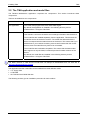
Icons
The following icons are used throughout the manual.
Icon
Name
Description
Remark
Useful information or tips.
Caution
Read the text that follows carefully in order to insure correct operation.
v
Preface
TMA
Software version
This manual describes the features of TMA version S0004/02000.
Your feedback
Your satisfaction about this purchase is an extremely important priority to all of us at Telindus.
Accordingly, all electronic, functional and cosmetic aspects of this new unit have been carefully and
thoroughly tested and inspected. If any fault is found with this unit or should you have any other qualityrelated comment concerning this delivery, please submit the Quality Comment Form on our web page at
http://www.telindusproducts.com/quality.
vi
TMA
Preface
Table of contents
User manual................................................................................................1
1. Introduction ............................................................................................................. 3
2. Installing TMA.......................................................................................................... 4
2.1
2.2
2.3
2.4
2.5
2.6
2.7
2.8
System requirements ......................................................................................................5
The TMA application and model files ..............................................................................6
Installing TMA from floppy disks......................................................................................7
Installing TMA from CD-ROM........................................................................................10
Installing TMA from the Telindus web site.....................................................................13
Location of the TMA files...............................................................................................16
Remarks on updating and uninstalling TMA..................................................................17
What TMA changes in the registry ................................................................................20
3. Connecting to a device ......................................................................................... 21
3.1
3.2
3.3
3.4
What are IP, proxied IP and non-IP devices? ...............................................................22
Direct connection to a device ........................................................................................23
IP connection to an IP device........................................................................................26
Proxied IP connection to a non-IP device .....................................................................29
4. Opening a TMA session........................................................................................ 34
4.1
4.2
4.3
4.4
Starting TMA .................................................................................................................35
Connecting to a device..................................................................................................36
Selecting a device .........................................................................................................45
The TMA command line ................................................................................................61
5. Opening a TMA session – examples ................................................................... 66
5.1
5.2
5.3
5.4
5.5
Example 1 – a direct connection ...................................................................................67
Example 2 – an IP connection.......................................................................................68
Example 3 – a proxied IP connection ............................................................................69
Example 4 – a dial-out connection ................................................................................70
Some remarks on dial-out connections .........................................................................71
6. The TMA window ................................................................................................... 74
6.1
6.2
6.3
6.4
6.5
6.6
6.7
6.8
The TMA window structure............................................................................................75
The menu bar ................................................................................................................76
The toolbar ..................................................................................................................102
The containment tree window .....................................................................................104
The attribute window ...................................................................................................105
The action window.......................................................................................................112
The structured value window.......................................................................................114
The status bar .............................................................................................................122
Continued on next page
vii
Preface
TMA
Table of contents (continued)
Reference manual .................................................................................. 124
7. User instantiatable objects.................................................................................126
7.1
7.2
7.3
What is a user instantiatable object? .......................................................................... 127
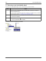
Adding a user instantiatable object ............................................................................. 128
Removing a user instantiatable object ........................................................................ 129
8. User defining values using the custom.txt file .................................................130
8.1
8.2
8.3
8.4
8.5
8.6
8.7
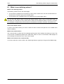
What is user defining values? ..................................................................................... 131
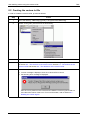
Creating the custom.txt file.......................................................................................... 132
The structure of the custom.txt file .............................................................................. 133
The sections of the custom.txt file............................................................................... 134
The definitions of the custom.txt file............................................................................ 135
An example of a custom.txt file ................................................................................... 142
Reading the custom.log file......................................................................................... 144
9. The interactive sub-system picture ...................................................................150
9.1
9.2
9.3
9.4
9.5
9.6
9.7
9.8
9.9
9.10
9.11
9.12
What is an interactive sub-system picture?................................................................. 151
The sub-system picture window.................................................................................. 152
Creating a *.usr file ..................................................................................................... 153
The sections of the *.usr file........................................................................................ 154
The FRONT and REAR section of the *.usr file .......................................................... 156
The BUTTONS section of the *.usr file ....................................................................... 165
The ACTIONS section of the *.usr file......................................................................... 167
The action output window ........................................................................................... 169
The action commands................................................................................................. 170
The help text ............................................................................................................... 184
Example of a *.usr file ................................................................................................. 189
Reading the picture.log file ......................................................................................... 192
10. Downloading software ........................................................................................196
10.1 Downloading firmware to the flash memory ................................................................ 197
10.2 Downloading files to the file system ............................................................................ 200
10.3 Remarks on downloading files to the file system ........................................................ 201
11. Telindus Memory Loader (TML) .........................................................................202
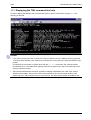
11.1 Displaying the TML command line help ...................................................................... 203
11.2 Starting TML from the command line .......................................................................... 204
11.3 Starting TML from the command line – examples....................................................... 206
12. The Cms2Serv.ini file ..........................................................................................209
12.1 Parts of the Cms2Serv.ini file...................................................................................... 210
12.2 Adding parts to the Cms2Serv.ini file .......................................................................... 212
Continued on next page
viii
TMA
Preface
Table of contents (continued)
13. Troubleshooting .................................................................................................. 213
13.1
13.2
13.3
13.4
Failing network connection..........................................................................................214
Failing device selection ...............................................................................................220
Failing software download...........................................................................................229
Other possible problems .............................................................................................230
Annexes ..................................................................................................235
Annex A: abbreviations............................................................................................. 237
Annex B: TMA error messages ................................................................................ 238
TMA start errors....................................................................................................................238
TMA CLI command line errors..............................................................................................239
Alias errors ...........................................................................................................................240
Connect errors ......................................................................................................................241
Edit errors .............................................................................................................................242
Export errors .........................................................................................................................243
Import errors .........................................................................................................................244
Download errors ...................................................................................................................245
Sub-system picture errors.....................................................................................................246
NACK messages ..................................................................................................................247
Internal communication errors ..............................................................................................248
Annex C: product information.................................................................................. 249
ix
TMA
User manual
User manual
1
TMA
2
User manual
TMA
Introduction
1. Introduction
This chapter gives an introduction to the Telindus Maintenance Application (TMA). First it describes what
TMA is. Then it gives the main features of TMA.
What is TMA?
Due to the continuous evolution in the domain of data communication technology, data communication
devices become more and more complex to install and control. This results in a need for an easy
maintenance tool.
The Telindus Maintenance Application (TMA) is such a tool. It offers you full control over any Telindus
device in your network in combination with a user-friendly man – machine interface (MMI).
Features of TMA
The most important features of TMA are:
•
•
•
•
•
•
•
•
•
•
•
direct connection via the device its control port
remote connection over the network
password protected access to the device
reading and changing the device configuration
configuration profiles can be stored on hard disk for re-use
instant status, performance and alarm information
real time monitoring of the interchange circuits (RS-530, V.35, V.36, X.21, G.703, IP Router, etc.)
real time monitoring of modem line parameters
execution of diagnostic tests
downloading software to the device
sub-system picture.
User manual
3
Installing TMA
TMA
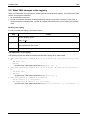
2. Installing TMA
This chapter explains how to install TMA. First it gives you the system requirements. Read these
requirements carefully to make sure your computer will be able to run TMA. Then it explains the
difference between the TMA application and the TMA model files. After that, the installation procedure is
given starting from three different media: floppy disks, CD-ROM and the Telindus web site.
The following table gives an overview of this chapter.
Section
4
Title
Page
2.1
System requirements
5
2.2
The TMA application and model files
6
2.3
Installing TMA from floppy disks
7
2.4
Installing TMA from CD-ROM
10
2.5
Installing TMA from the Telindus web site
13
2.6
Location of the TMA files
16
2.7
Remarks on updating and uninstalling TMA
17
2.8
What TMA changes in the registry
20
User manual
TMA
Installing TMA
2.1 System requirements
This section states the minimum system requirements to allow a successful installation of TMA. These
requirements are:
System component
operating system
Minimum requirement
• Microsoft Windows 95
•
•
•
•
data input device
Microsoft Windows 98
Microsoft Windows NT 4.0
Microsoft Windows 2000
Microsoft Windows XP
Depending on how TMA is delivered to you:
• 3 ½” floppy drive
• CD-ROM drive
• internet access
free disk space
• 4 MB without model files
• 30 MB with model files (1)
total amount of RAM
• 16 MB for Windows 95/98
• 32 MB for Windows NT 4.0
• 64 MB for Windows 2000
communication port
• serial COM port: 9600, 8+N
and / or
• Ethernet card
networking
TCP/IP networking installed and configured
(1)
Because the model files delivered with TMA evolve as the devices evolve, their size tends to increase
with each new release. The figure specified in the table above, is the size of TMA and the model files as it
was when this manual was written. For future releases of TMA, this figure may be incorrect.
User manual
5
Installing TMA
TMA
2.2 The TMA application and model files
The Telindus Maintenance Application comprises two components. This section introduces these
components.
TMA can be divided into two components:
Part
the application
Description
This is the TMA program itself, also called TMA engine.
By default, the application is installed in the following directory and its
subdirectories: C:\Program Files\TMA.
the model files
Each Telindus device has its own model file. This file contains the information
TMA needs to connect to the device and exchange information with the device.
The model files are installed separately from the application. This because the
model files evolve as the device evolves. The model files delivered with the
device correspond with the latest firmware of the device. This means that if you
add devices to your network containing more recent firmware than the current
devices, then the model files may have to be re-installed.
The model files are backwards compatible. This means that the latest model
files support not only the latest, but also all previous firmware revisions of the
device.
By default, the model files are installed in the following directory and its
subdirectories: C:\Program Files\TMA.
The latest versions of TMA and the model files can always be downloaded from our web site at
http://www.telindusproducts.com/tma.
The application and the model files can be installed from three different media:
• 3 ½” floppy disks
• a CD-ROM
• the Telindus World Wide Web site.
The following sections give an installation procedure for each medium.
6
User manual
TMA
Installing TMA
2.3 Installing TMA from floppy disks
Normally TMA is delivered on CD-ROM. Exceptionally it is delivered on 3 ½” floppy disks. This section
explains how to install TMA from these disks.
The following table gives an overview of this section.
Section
Title
Page
2.3.1
Installing the application from floppy disk
8
2.3.2
Installing the model files from floppy disk
9
User manual
7
Installing TMA
TMA
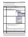
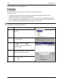
2.3.1 Installing the application from floppy disk
To install the TMA application from the floppy disks, proceed as follows:
Step
Action
1
Insert the floppy disk labelled TMA in the floppy drive.
2
On the taskbar, select:
Start ! Run…
3
In the Run window:
type A:\setup and click on OK.
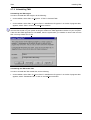
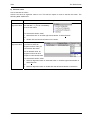
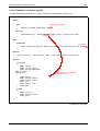
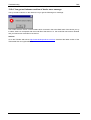
4
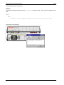
The InstallShield Wizard guides you through the set-up process.
The following figure displays a few steps of the installation procedure:
8
User manual
TMA
Installing TMA
2.3.2 Installing the model files from floppy disk
To install the TMA model files from the floppy disks, proceed as follows:
Step
Action
1
Insert the floppy disk labelled TMA Model Files in the floppy drive.
2
On the taskbar, select:
Start ! Run…
3
In the Run window:
type A:\setup and click on OK.
4
User manual
The InstallShield Wizard guides you through the set-up process.
9
Installing TMA
TMA
2.4 Installing TMA from CD-ROM
This section explains how to install TMA from the CD-ROM. The following table gives an overview of this
section.
Section
10
Title
Page
2.4.1
Installing the application from CD-ROM
11
2.4.2
Installing the model files from CD-ROM
12
User manual
TMA
Installing TMA
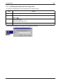
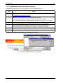
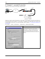
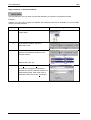
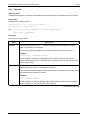
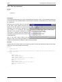
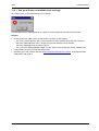
2.4.1 Installing the application from CD-ROM
To install the TMA application from the CD-ROM, proceed as follows:
Step
Action
1
Insert the CD-ROM in the CD-ROM drive.
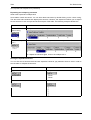
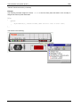
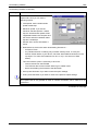
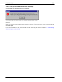
2
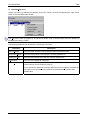
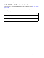
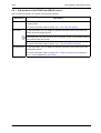
Windows automatically displays a HTML page where you can select from the following:
Option
Choose this option to …
USER AND REFERENCE MANUALS
consult the manuals included on the CD-ROM.
INSTALL TMA ENGINE FROM CD
install the TMA program from the CD-ROM.
INSTALL TMA MODEL FILES FROM CD
install the TMA model files from the CD-ROM.
DOWNLOAD LATEST TMA FROM THE WEB
download the most recent TMA program and / or
model files from the Telindus web site.
CREATE FLOPPIES FOR TMA
create installation floppies for TMA. This
enables you to distribute TMA on floppy disks for
installation purposes.
If the HTML page does not appear after insertion of the CD-ROM, then:
1. On the taskbar select Start ! Run…
2. In the Run window type X:\StartHtml, where X is the letter of your CD-ROM drive.
3. Click on the OK button.
3
Select INSTALL TMA ENGINE FROM CD.
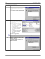
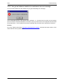
4
The InstallShield Wizard guides you through the set-up process.
The following figure displays a few steps of the installation procedure:
User manual
11
Installing TMA
TMA
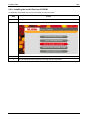
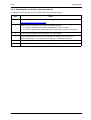
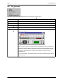
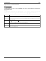
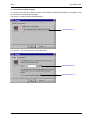
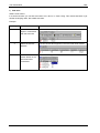
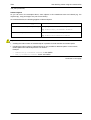
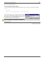
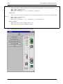
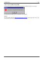
2.4.2 Installing the model files from CD-ROM
To install the TMA model files from the CD-ROM, proceed as follows:
Step
12
Action
1
Insert the CD-ROM in the CD-ROM drive.
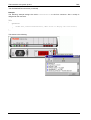
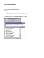
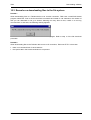
2
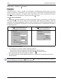
Windows automatically displays a HTML page as shown below:
3
Select INSTALL TMA MODEL FILES FROM CD.
4
The InstallShield Wizard guides you through the set-up process.
User manual
TMA
Installing TMA
2.5 Installing TMA from the Telindus web site
The latest version of the TMA application and of the TMA model files is always available on the Telindus
web site. This section explains how to download and install the application and the model files from the
web site.
The following table gives an overview of this section.
Section
Title
Page
2.5.1
Installing the application from the web site
14
2.5.2
Installing the model files from the web site
15
User manual
13
Installing TMA
TMA
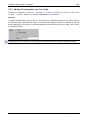
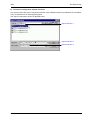
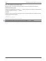
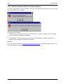
2.5.1 Installing the application from the web site
To install the TMA application from the Telindus web site, proceed as follows:
Step
1
Action
Open your web browser and enter the following address:
http://www.telindusproducts.com/tma
2
Read the License Agreement for Telindus software carefully.
• If you agree with the terms stated in the agreement, click on I agree.
• If you do not agree with the terms stated in the agreement, click on I don’t agree.
3
Click on the link TMA part 1: engine (manual included) rev. xxx (xxxx KByte).
4
Save the executable file S0004xxx.exe (where xxx stands for the revision) to a
temporary directory on your hard disk. For instance, C:\temp\S0004010.exe.
5
In this temporary directory, double-click on the executable file S0004xxx.exe.
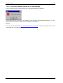
6
The InstallShield Wizard guides you through the set-up process.
The following figure displays a few steps of the installation procedure:
14
User manual
TMA
Installing TMA
2.5.2 Installing the model files from the web site
To install the TMA model files from the Telindus web site, proceed as follows:
Step
1
Action
Open your web browser and enter the following address:
http://www.telindusproducts.com/tma
2
Read the License Agreement for Telindus software carefully.
• If you agree with the terms stated in the agreement, click on I agree.
• If you do not agree with the terms stated in the agreement, click on I don’t agree.
3
Click on the link TMA part 2: data files rev. xxx (xxxx KByte).
4
Save the executable file S0011xxx.exe (where xxx stands for the revision) to a
temporary directory on your hard disk. For instance, C:\temp\S0011020.exe.
5
In this temporary directory, double-click on the executable file S0011xxx.exe.
6
The InstallShield Wizard guides you through the set-up process.
User manual
15
Installing TMA
TMA
2.6 Location of the TMA files
If you did not change the default file location during the set-up, then the TMA related directories and files
can be found in the directory C:\Program Files\TMA. This directory has the following subdirectories:
Directory
\bin
This directory contains …
the executables.
This comprises the TMA executable and some extra executables TMA
sometimes summons (such as TML, TmaTftp, …).
\config
the configuration files.
These are the *.ini files. If you create a custom.txt file, you should also place it
here.
\log
the log files.
Sometimes errors are logged to a file. These files can be found in this directory.
\manuals
the user manual of TMA (this manual).
\model
the model files.
TMA needs the model files to be able to communicate with the Telindus devices.
These *.mod files are located in this directory.
\picture
the sub-system picture files.
These are the *.bmp and *.def files that are necessary to display the sub-system
picture of a Telindus device.
\snmp
the Telindus MIB files.
When using an SNMP browser, you need the MIB files of the Telindus devices.
These *.mib files are located in this directory.
\snmp_info
the SUM files.
The *.sum files give the relationship between the attributes as they are displayed
in TMA and the parameters you can see using an SNMP browser.
16
User manual
TMA
Installing TMA
2.7 Remarks on updating and uninstalling TMA
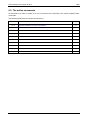
This section gives some remarks on updating and uninstalling TMA. The following table gives an
overview of this section.
Section
Title
Page
2.7.1
Updating TMA
18
2.7.2
Uninstalling TMA
19
User manual
17
Installing TMA
TMA
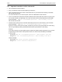
2.7.1 Updating TMA
Updating the TMA engine
If you want to install a newer version of the TMA engine, then it is not necessary to uninstall the previous
version first. You can just install the new version “on top” of the previous one.
Updating the TMA model files
If you want to install a newer version of the TMA model files, then it is not necessary to uninstall the
previous version first. You can just install the new version “on top” of the previous one.
Should you try to install an older version of the TMA model files on top of a newer one, then you get the
following message:
Warning: you are trying to install an older version of the TMA Model Files
(S0004/03200) over a more recent version (S0004/03300). If you really want to do
so, please uninstall the current version and then run this installer again.
18
User manual
TMA
Installing TMA
2.7.2 Uninstalling TMA
Uninstalling the TMA engine
In order to uninstall the TMA engine, do the following:
• On the taskbar, select Start ! Programs ! TMA ! Uninstall TMA.
or
• On the taskbar, select Start ! Control Panel ! Add/Remove Programs ! in the list of programs that
appears, select TMA ! click on the Add/Remove button.
In case several TMA applications are installed on your computer (for instance TMA and TMA CLI), the
common files remain on your system as long as at least one TMA application remains on your computer.
If also this last TMA application is uninstalled, then the system asks you whether to remove the common
files. You may answer Yes To All.
Uninstalling the TMA model files
In order to uninstall the TMA model files, do the following:
• On the taskbar, select Start ! Control Panel ! Add/Remove Programs ! in the list of programs that
appears, select TMA Model Files ! click on the Add/Remove button.
User manual
19
Installing TMA
TMA
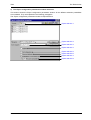
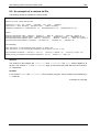
2.8 What TMA changes in the registry
When you install TMA, some entries are added to the Microsoft Windows registry. This section lists these
entries. This might be interesting …
• for documentation purposes,
• should you experience troubles installing (different) TMA (products and/or versions). In that case, a
solution might be to uninstall TMA, remove all possible TMA references from the registry and reinstall
TMA.
Browsing the registry
In order to browse the registry, proceed as follows:
Step
1
Action
On the taskbar, select:
Start ! Run…
2
In the Run window:
type regedit and click on OK.
3
The registry editor opens.
The TMA entries in the registry
The following entries are added to the Microsoft Windows registry when TMA installs:
•
HKEY_LOCAL_MACHINE ! SOFTWARE ! Microsoft ! Windows ! CurrentVersion ! App Paths
!
− TMA Model Files
− TMA.exe
− … (possible other TMA related applications, e.g. TmaCli.exe, …)
•
HKEY_LOCAL_MACHINE ! SOFTWARE ! Microsoft ! Windows ! CurrentVersion ! Uninstall
!
− TMA Model Files
− TMA.exe
− … (possible other TMA related applications, e.g. TmaCli.exe, …)
• HKEY_LOCAL_MACHINE ! SOFTWARE ! Telindus !
−
−
TMA ! <version, e.g. S0004/xxx00>
TMA Model Files ! <version, e.g. S0011/xxx00>
− … (possible other TMA related applications, e.g. TmaCli ! <version, e.g. S0106/xxx00>, …)
20
User manual
TMA
Connecting to a device
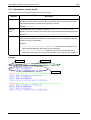
3. Connecting to a device
Once the TMA application and the model files are installed, you are ready to interconnect the computer
running TMA and a Telindus device. This is explained in this chapter.
First the terms IP device, proxied IP device and non-IP device are explained, for they are used in this and
the following chapters.
The following table gives an overview of this chapter.
Section
Title
Page
3.1
What are IP, proxied IP and non-IP devices?
22
3.2
Direct connection to a device
23
3.3
IP connection to an IP device
26
3.4
Proxied IP connection to a non-IP device
29
User manual
21
Connecting to a device
TMA
3.1 What are IP, proxied IP and non-IP devices?
Because in this and the following chapters the terms IP device, proxied IP device and non-IP device are
often used, they are explained in this section.
The following table gives a definition of each term together with an example:
Term
IP device
Definition
An IP device is a Telindus access device …
• in which you can configure an IP address.
• that has a dedicated LAN port through which you can connect the device to a
LAN.
Example
The Crocus Inverse Multiplexer is an IP device. You can configure an IP address
in the Crocus Inverse Multiplexer using the crocusInvMux/lanInterface/ipAddress
attribute. The Crocus Inverse Multiplexer can be connected to a LAN through its
TPI port located at the back of the device.
Other IP devices are for instance: Orchid 1003 LAN, Crocus Router Interface,
Crocus Router 2M, Telindus 1421 SHDSL Router.
non-IP device
A non-IP device is a Telindus access device …
• in which you can not configure an IP address.
• has no dedicated LAN port and therefore can not be connected directly to a
LAN.
Example
The Crocus SDSL F baseband modem is a non-IP device. You can not configure
an IP address in the Crocus SDSL F and you can not connect it to a LAN through
a dedicated LAN port.
Other non-IP devices are for instance: Aster 4 F, Crocus HDSL F, Crocus SDSL
F, Crocus FO10M.
proxied IP device
A proxied IP device is actually a non-IP device. This means it is a Telindus access
device …
• in which you can not configure an IP address. However, you can assign an IP
address to the device using a management concentrator as proxy IP device
(refer to Section 3.4 - Proxied IP connection to a non-IP device).
• has no dedicated LAN port and therefore can not be connected directly to a
LAN. This is done through a management concentrator which is an IP device
and therefore can be connected to a LAN through its dedicated LAN port.
Example
The Crocus SDSL F baseband modem is a non-IP device. However, by
connecting the Orchid 1003 LAN to the modem and by assigning an IP address to
it in the Orchid 1003 LAN, the modem becomes a proxied IP device. The Orchid
1003 LAN on its turn, is connected through its LAN port to a LAN. I.e. it is as if the
modem is connected to the LAN, although not directly.
22
User manual
TMA
Connecting to a device
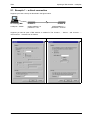
3.2 Direct connection to a device
This section explains how to make a direct connection between the computer running TMA and a
Telindus device.
The following table gives an overview of this section.
Section
Title
Page
3.2.1
What is a direct connection?
24
3.2.2
To which Telindus devices can you make a direct connection?
25
3.2.3
DB25 – DB9 interconnection cable
25
User manual
23
Connecting to a device
TMA
3.2.1 What is a direct connection?
A direct connection is a connection between a COM port of the computer and the auxiliary port (also
called control port) of a Telindus device. Such a connection is made by means of a straight male-female
DB9 cable.
There are some exceptions. The Orchid 1003 LAN, for instance. This device has an RJ45 control port.
Consequently, the connection is made by means of a DB9 - RJ45 cable. This cable is delivered with the
Orchid 1003 LAN.
The following figure shows an example of a direct connection to a Table Top and Card Version modem:
computer running TMA
Card Version modem
Table Top modem
COM 1
auxiliary port
COM 2
straight male-female DB9 cable
Once the connection is made then the computer running TMA is able to reach the modem.
24
User manual
TMA
Connecting to a device
3.2.2 To which Telindus devices can you make a direct connection?
Every Telindus device that is manageable with TMA has a control port. Hence, you can make a direct
connection to any of these devices, regardless of the fact it is a non-IP, IP or proxied IP device.
3.2.3 DB25 – DB9 interconnection cable
If the COM port you want to use has a DB25 connector, then a different cable has to be used. Such a
cable has the following layout:
Female DB25 connector
for connection towards the computer
Male DB9 connector
for connection towards the Telindus device
Pin
Signal
Input / output
Pin
Signal
Input / output
2
TXD
output
3
TXD
input
3
RXD
input
2
RXD
output
4
RTS
output
7
RTS
input
5
CTS
input
8
CTS
output
6
DSR
input
6
DSR
output
7
GND
-
5
GND
-
20
DTR
output
4
DTR
input
User manual
25
Connecting to a device
TMA
3.3 IP connection to an IP device
This section explains how to make an IP connection between the computer running TMA and a Telindus
IP device.
The following table gives an overview of this section.
Section
26
Title
Page
3.3.1
What is an IP connection?
27
3.3.2
To which Telindus devices can you make an IP connection?
28
3.3.3
Basic IP device settings to enable an IP connection
28
User manual
TMA
Connecting to a device
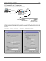
3.3.1 What is an IP connection?
A connection via IP is a connection between:
• the LAN port of the IP device and the IP network at one side
• the network port of the computer and the IP network at the other side.
The following figure shows an example of a connection via IP to an Orchid 1003 LAN Table Top and Card
Version:
computer running TMA
Table Top Orchid
TPI port
IP
network port
TPI port
Card Version Orchid
As opposed to a direct connection, making the physical connection alone is not sufficient to establish an
IP connection between the computer and the IP device. A few basic settings have to be made in the IP
device.
User manual
27
Connecting to a device
TMA
3.3.2 To which Telindus devices can you make an IP connection?
You can make an IP connection to every Telindus device that has a dedicated LAN port through which
you can connect the device to a LAN. Hence, you can only make a connection via IP to a Telindus IP
device, not to a non-IP device.
There is a way to make an IP connection to a non-IP device. However, this involves using a management
concentrator with a particular configuration. In that case, the non-IP device becomes a proxied IP device.
For more information, refer to Section 3.4 - Proxied IP connection to a non-IP device.
3.3.3 Basic IP device settings to enable an IP connection
To establish an IP connection between the computer running TMA and the IP device, a few basic
parameters (called attributes) have to be set in the IP device. These attributes are:
Attribute
IP address
Description
This is a unique address which is assigned to the IP device. By doing this, other
devices on the IP network can contact the IP device.
Examples
The following examples display the IP address attribute location in the
containment tree of some Telindus IP devices:
• Orchid 1003 LAN: o1003/interfaces/lanInterface/ipAddress
• Crocus Router 2M or Router Interface: crocusRouter/lanInterface/ipAddress
• Crocus Inverse Multiplexer: crocusInvMux/lanInterface/ipAddress
default gateway
This is the gateway of the IP segment the IP device is connected to. I.e. the IP
address of the router which handles packets destined for another network.
Examples
The following examples display the default gateway attribute location in the
containment tree of some Telindus IP devices:
• Orchid 1003 LAN: o1003/router/defaultRoute/gateway
• Crocus Router 2M or Router Interface: crocusRouter/router/defaultRoute/gateway
• Crocus Inverse Multiplexer: crocusInvMux/lanInterface/defaultRoute
For more detailed information, refer to the user manual of the IP device.
Once these attributes are set then the computer running TMA is able to reach the IP device over an IP
network.
28
User manual
TMA
Connecting to a device
3.4 Proxied IP connection to a non-IP device
As stated in Section 3.3 - IP connection to an IP device, it is not possible to make a true IP connection to
a non-IP device. This because non-IP devices do not have a dedicated LAN port through which you can
connect them to a LAN. However, using a management concentrator, you can make a proxied IP
connection to a non-IP device. This is explained in this section.
The following table gives an overview of this section.
Section
Title
Page
3.4.1
What is a management concentrator?
3.4.2
Which Telindus devices are management concentrators?
3.4.3
A management concentrator as a proxy IP device
30
3.4.4
A proxied IP connection to a non-IP device – example
31
3.4.5
Basic management concentrator settings to enable a proxied IP connection
32
User manual
30
29
Connecting to a device
TMA
3.4.1 What is a management concentrator?
A management concentrator is a device that collects management information from the network units (i.e.
the Telindus devices in the network) and passes it to a network management system (e.g. HP
OpenView). So a management concentrator is situated between the network units and the network
management system. In other words, it is a key element for centralised network management.
3.4.2 Which Telindus devices are management concentrators?
Examples of management concentrator are:
• the Orchid 1003 LAN (the predecessor of the Telindus 1035 Orchid).
• the Telindus 1031, 1032, 1033 and 1034 Router (note that their management concentrator capabilities
are limited due to hardware limitations).
• the Telindus 1035 Orchid (the successor of the Orchid 1003 LAN).
For more detailed information on these devices, refer to their user manuals.
3.4.3 A management concentrator as a proxy IP device
You can connect a Telindus non-IP device (e.g. a Crocus modem) to a management concentrator. In the
management concentrator configuration, you can assign an IP address to this non-IP device. In that
case, the non-IP device becomes a proxied IP device. I.e. you can now access the non-IP device over an
IP network through the management concentrator. In other words, the management concentrator acts as
proxy IP device for the non-IP device.
This implies that as opposed to the management concentrator, the non-IP device is not directly
connected through a dedicated LAN port to the IP network. An example of an IP connection between the
computer running TMA and a non-IP device is given in the following paragraph.
30
User manual
TMA
Connecting to a device
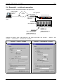
3.4.4 A proxied IP connection to a non-IP device – example
Consider the following components which have to be interconnected:
•
•
•
•
•
the computer running TMA
the IP network
a CN4 card nest
a Card Version modem
a Card Version Orchid 1003 LAN.
The following figure shows the interconnection between these components:
computer running TMA
Card Version Orchid
Card Version modem
NMS connectors
TPI port
network port
IP
The following table gives an overview of the connections shown in the figure above. The overview starts
at the computer running TMA.
The …
is connected to the …
via …
network port of the computer
IP network
an RJ45 network cable.
TPI port of the Orchid 1003 LAN
IP network
an RJ45 network cable.
NMS port of the Orchid 1003
LAN
NMS port of the CN4 card nest
a straight RJ45 cable.
NMS port of the CN4 card nest
high speed NMS bus of the
Card Version modem
the high speed NMS bus on the
backplane of the CN4 card nest.
As opposed to a direct connection, making the physical connection alone is not sufficient to establish a
proxied IP connection between the computer and the non-IP device. A few basic settings have to be
made in the Orchid 1003 LAN. These are shown in the following paragraph.
User manual
31
Connecting to a device
TMA
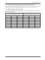
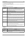
3.4.5 Basic management concentrator settings to enable a proxied IP connection
To establish an IP connection between the computer running TMA and the non-IP device, a few basic
parameters (called attributes) have to be set in the management concentrator:
• The first two attributes are the IP address and default gateway of the management concentrator itself.
These parameters are already explained in Section 3.3 - IP connection to an IP device.
• The other attributes are located in the object table of the management concentrator:
nmsgroup/objectTable. The relevant attributes are:
Attribute
ipAddress
Description
Use this attribute to assign an IP address to the non-IP device.
The IP address should belong to the sub-network of the management
concentrator. For example, if the IP address of the management concentrator is
192.168.4.5 with subnetmask 255.255.255.0 then the IP address of the network
unit should also be within the range from 192.168.4.1 to 192.168.4.254.
addressType
The management concentrator has to know how it can contact the connected
non-IP device. Therefore, use the addressType attribute to specify the type of
address:
• a relative address
• an absolute address.
For more information on these address types, refer to Section 4.3.3 - The
Connect… – Select device… window selections, Select device... selection 5 –
NMS address.
addressValue
If you set the addressType attribute to absolute, then use the addressValue attribute to
specify the absolute address value.
Continued on next page
32
User manual
TMA
Connecting to a device
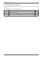
Proxied IP connection to a non-IP device (continued)
Attribute
port
or
exitPort
Description
The exit port specifies through which port of the management concentrator the
network unit can be reached.
In case of the exitPort attribute, the underlying attributes are:
Attribute
exitPortType
Description
Use this attribute to specify whether the non-IP device is
reachable through …
• one of the asynchronous ports of the management
concentrator (port). In this case, also set the attribute
portNumber.
• the high speed bus of the CN4 Card Nest (rack). In
this case, also set the attributes cardnestAddress,
cardPosition and modem.
portNumber
Use this attribute to specify through which asynchronous
port of the management concentrator the non-IP device
can be reached.
cardnestAddress
Use this attribute to specify the CN4 Card Nest address
in which the non-IP device (Card Version) resides.
cardPosition
Use this attribute to specify the position of the non-IP
device (Card Version) in the CN4 Card Nest.
modem
Use this attribute to select the device on the non-IP
multi-device (Card Version Twin, Quad, etc.): A, B, C or
D.
For more detailed information, refer to the user manual of the management concentrator.
Once these attributes are set then the computer running TMA is able to reach the non-IP device over an
IP network.
User manual
33
Opening a TMA session
TMA
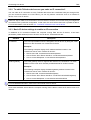
4. Opening a TMA session
Once the physical connections are made, you are able to open a TMA session on a Telindus device. First
this chapter explains how to start TMA. Then it describes how to connect to the network and how to
select a device on this network.
The following table gives an overview of this chapter.
Section
34
Title
Page
4.1
Starting TMA
35
4.2
Connecting to a device
36
4.3
Selecting a device
45
4.4
The TMA command line
61
User manual
TMA
Opening a TMA session
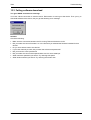
4.1 Starting TMA
Before a TMA session can be opened, the application itself has to be started.
To start TMA, proceed as follows:
Step
Action
1
On the taskbar, select Start.
2
In the start menu, select Programs.
3
In the program menu, select the program group TMA.
4
In the program group TMA, select TMA.
⇒ The TMA window appears.
User manual
35
Opening a TMA session
TMA
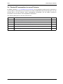
4.2 Connecting to a device
After you made the necessary hardware connections, you have to establish a software connection. I.e.
you have to establish a link between the computer running TMA and the Telindus device through which
you want to access the network. First this section explains how to display the Connect… – Device…
window. Then it describes in detail the different connection possibilities.
The following table gives an overview of this section.
Section
36
Title
Page
4.2.1
Displaying the Connect… – Device… window
37
4.2.2
The Connect… – Device… window selections
38
User manual
TMA
Opening a TMA session
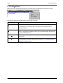
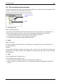
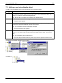
4.2.1 Displaying the Connect… – Device… window
To display the Connect… – Device… window, proceed as follows:
Step
1
Action
Start the TMA application. Refer to Section 4.1 - Starting TMA.
⇒ The TMA window appears.
2
In the TMA window, either…
• press on the Connect to a device button:
• or press the shortcut key: Ctrl+N
• or select from the menu bar: Connect ! Device…
⇒ The Connect… – Device… window appears.
User manual
37
Opening a TMA session
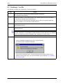
TMA
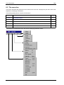
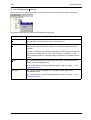
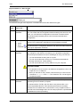
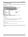
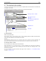
4.2.2 The Connect… – Device… window selections
The following figure displays the Connect… – Device… window. All the different selection possibilities are
numbered. They are explained in the following paragraphs.
Device... selection 1
Device... selection 2
Device... selection 3
Device... selection 4
Device... selection 5
Device... selection 6
38
User manual
TMA
Opening a TMA session
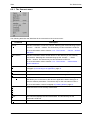
Device... selection 1 - Serial
Make this selection if you want to make a direct (also called serial) connection as described in Section
3.2 - Direct connection to a device. In that case you have to specify which COM port of the computer is
connected to the control port of the Telindus device.
Select one of the four possibilities displayed in the drop-down box:
•
•
•
•
COM 1
COM 2
COM 3
COM 4.
The TMA Comms Handler
The TMA Comms Handler is a part of the TMA software that handles the communication towards the
connected devices. If you connect through one of the COM ports of your computer, the TMA Comms
Handler locks this COM port for other applications. If you close all TMA sessions and even if you close
the TMA application, the TMA Comms Handler waits a certain period before it releases the previously
used COM port(s). You can change this timeout with the WaitClose parameter in the Cms2Serv.ini file. As
default, this timeout period is set to 5 minutes. For more information on this and other communication
parameters, refer to Section 12.1 - Parts of the Cms2Serv.ini file.
However, you can force the TMA Comms Handler to close even if the WaitClose time is not elapsed yet. To
do so, proceed as follows:
Step
Action
1
Move the Windows arrow to the TMA Comms Handler icon on the taskbar.
2
Press on the right mouse button.
3
From the pop-up menu, choose Close.
User manual
39
Opening a TMA session
TMA
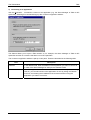
Device... selection 2 - Dial out: No
Make this selection if you do not wish to establish a dial-out connection.
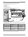
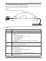
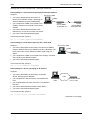
Device... selection 3 - Dial out: PSTN modem
Make this selection if you wish to establish a dial-out connection. An example of a dial-out connection is
given below.
Example:
Suppose you want to connect to an Orchid 1003 LAN via a dial-out connection. A possible setup is given
in the figure below:
Orchid 1003 LAN
COM 1 … 4
PSTN
control port
PC running
TMA
PSTN modem 1
PSTN modem 2
DTE interface
DTE interface
The following table gives an overview of the connections shown in the figure above. The overview starts
at the computer running TMA.
The …
is connected to the …
via …
COM port of the computer
DTE interface of PSTN modem
1
a DTE – DCE interface cable.
PSTN port of PSTN modem 1
PSTN port of PSTN modem 2
a dial-out connection over the
PSTN network.
DTE interface of PSTN modem
2
control port of the Orchid 1003
LAN
a DTE – DCE interface cable.
If the computer has an internal PSTN modem, verify which COM port it uses.
40
User manual
TMA
Opening a TMA session
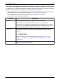
Device... selection 4 - IP address
Make this selection if you want to make a connection over an IP network as described in Section 3.3 - IP
connection to an IP device and Section 3.4 - Proxied IP connection to a non-IP device. Enter the IP
address of the Telindus device you want to connect to.
User manual
41
Opening a TMA session
TMA
Device... selection 5 - Assign to MAC
Connecting TMA – normal situation
Normally, it is possible to make a direct connection with TMA to every Telindus device that has a control
port. Also, when a Crocus Router Interface is inserted in a Crocus baseband modem, the Router
Interface can be reached on relative address 0 and the modem itself on relative address 1 (for more
information on the relative addressing method, refer to Section 4.3.3 - The Connect… – Select device…
window selections, Select device... selection 5 – NMS address).
Connecting TMA – Crocus HS
An exception to this rule is the Crocus HS baseband modem. In that case, you can only connect to the
Crocus HS through one of the exit ports of a management concentrator (refer to Section 4.3.3 - The
Connect… – Select device… window selections, Select device... selection 6 – Exitport). What is more,
when a Crocus Router Interface is inserted in a Crocus HS modem, only the modem can be accessed
with TMA. This would imply that a non-configured Router Interface (i.e. a Router Interface that has not
been assigned an IP address yet) is not accessible by TMA when it is present in a Crocus HS modem.
This would also mean that you are unable to configure the Router Interface. Hence, you would be unable
to assign an IP address to it.
That is why the Assign to MAC option is present in TMA: temporarily assign an IP address to the Crocus
Router Interface to enable you to configure the interface.
Continued on next page
42
User manual
TMA
Opening a TMA session
Device... selection 5 - Assign to MAC (continued)
How does the Assign to MAC option work?
Suppose you have a Crocus HS equipped with a Crocus Router Interface. The configuration of the
Router Interface is still in its default state (i.e. no IP address, no subnet mask, etc.). You want to access
the Router Interface with TMA in order to edit its configuration.
Proceed as follows:
Step
Action
1
In the Connect… Device… window, make the IP address selection. Enter the IP address
you want to temporarily assign to the Crocus Router Interface.
2
Tick the Assign to MAC selection box. Enter the MAC address of the Crocus Router
Interface. Enter the subnet mask that corresponds with the previously entered IP
address.
3
Hit the Next button.
⇒ The TMA window opens and displays the containment tree of the Crocus Router
Interface.
⇒ The previously entered IP address is now temporarily assigned to the Crocus Router
Interface. Temporarily because you will see the IP address in the Status group, but
not in the Configuration group. When the Router Interface reboots, the IP address is
lost.
4
Configure an IP address, a subnet mask and a default route in the Crocus Router
Interface. Refer to Section 3.3 - IP connection to an IP device.
5
Activate this configuration.
⇒ You now permanently assigned an IP address to the Crocus Router Interface. From
now on, you are able to access the Router Interface just by typing its IP address in
the Connect… – Device… window.
Important remarks
In order for the Assign to MAC option to work, …
• your computer running TMA has to be connected to the same IP segment as the Crocus Router
Interface.
• the configuration of the Crocus Router Interface has to be in its default state (as it leaves the factory).
If it is not, reload its default configuration by setting the appropriate DIP switch (refer to the user
manual of the Crocus Router Interface).
For additional information on the Crocus HS or Crocus Router Interface, refer to the corresponding user
manual.
User manual
43
Opening a TMA session
TMA
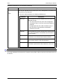
Device... selection 6 - Password
Enter here the device its password. This is the password of the Telindus device through which you want
to access the network. If no password is specified in the Telindus device, leave this field blank.
A Telindus device which is used for the first time has no password.
44
User manual
TMA
Opening a TMA session
4.3 Selecting a device
After you established a connection to the Telindus device through which you want to access the network,
you can choose to open a TMA session on:
• the device itself.
• a device located after the device through which you are accessing your network. However, the device
has to allow this.
Therefore, this chapter first explains when the Connect… – Select device… window appears and when it
does not. Then it shows how you can open the Connect… – Select device… window (in case the
currently connected device allows you to do so). This chapter also describes in detail the different
selection possibilities.
The following table gives an overview of this section.
Section
Title
Page
4.3.1
When does the Connect… – Select device… window appear?
46
4.3.2
Displaying the Connect… – Select device… window
47
4.3.3
The Connect… – Select device… window selections
49
User manual
45
Opening a TMA session
TMA
4.3.1 When does the Connect… – Select device… window appear?
As said before, the Connect… – Select device… window only appears if the device through which you
are accessing your network gives the possibility to open a TMA session on a device located further on in
the network.
To clarify this, two examples are given. The first example shows you a situation where you will get a
Connect… – Select device… window. The second example shows you a situation where you will not.
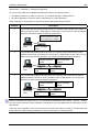
Example 1
Suppose you have the following set-up:
extended
link
PC running modem 1
TMA
modem 2
modem 3
modem 4
Your computer running TMA is connected on COM1 via a direct connection to the control port of modem
1. So, in the Connect… – Device… window you select Serial: com1, enter a Password if necessary and
press on the Next button.
In this situation the Connect… – Select device… window appears. This window allows you to open a
TMA session on:
• the modem through which you are accessing your network, i.e. modem 1.
• the modems located after modem 1, i.e. modem 2, 3 and 4.
Suppose you open a TMA session on modem 1 by selecting On device in the Connect… – Select
device… window. Suppose that after a while you want to open a TMA session on modem 3. In that case,
you can call the Connect… – Select device… window by selecting Select device… in the Connect menu.
For more information, refer to Section 4.3.2 - Displaying the Connect… – Select device… window.
For more information on the selection possibilities in the Connect… – Select device… window, refer to
Section 4.3.3 - The Connect… – Select device… window selections.
Example 2
Suppose you have the following set-up:
Orchid 1003 LAN
IP
PC running
TMA
modem
IP: 10.0.11.15
Your computer running TMA is connected over an IP network to an Orchid 1003 LAN. One of the ports of
the Orchid is connected to the control port of a modem. This modem is configured in the object table of
the Orchid. It is assigned IP address 10.0.11.15. So, in the Connect… – Device… window you select IP
address: 10.0.11.15, enter a Password if necessary and press on the Next button.
In this situation the Connect… – Select device… window does not appear. The TMA session is
automatically opened on the modem itself. This because connecting to a modem over IP does not allow
you to open TMA sessions on devices behind this modem (even if they are present). In that case, the
Select device… in the Connect menu is not selectable.
46
User manual
TMA
Opening a TMA session
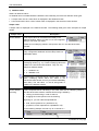
4.3.2 Displaying the Connect… – Select device… window
As said in the previous section, the Connect… – Select device… window only appears if the device
through which you are accessing your network allows this. If this is the case, then you will see the
following when connecting to such a device:
Step
1
Action
Start the TMA application. Refer to Section 4.1 - Starting TMA.
⇒ The TMA window appears.
2
Display the Connect… – Device… window. Refer to Section 4.2.1 - Displaying the
Connect… – Device… window.
3
Make your selection in the Connect… – Device… window. Refer to Section 4.2.2 - The
Connect… – Device… window selections.
If the connection to the device was successful and if the device allows to open a TMA
session on other devices further on in the network, then the Connect… – Select
device… window appears.
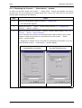
⇒ Depending on whether you are connected to a management concentrator or not, one
of the following Connect… – Select device… windows appears:
In case you connected to
a management concentrator …
In case you connected to
any other Telindus device …
Continued on next page
User manual
47
Opening a TMA session
TMA
Displaying the Connect… – Select device… window (continued)
If you already opened a TMA session on a device, but you want to open one on a device further on in the
network, proceed as follows:
Step
1
Action
In the TMA window, either…
• press on the Select device button:
• or press the shortcut key: Ctrl+D
• or select from the menu bar: Connect ! Select device…
⇒ The Connect… – Select device… window appears.
2
Make your selection in the Connect… – Select device… window. Refer to Section 4.3.3 The Connect… – Select device… window selections.
3
Press on the Next button.
⇒ A TMA session opens on the device.
48
User manual
TMA
Opening a TMA session
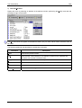
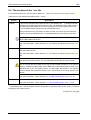
4.3.3 The Connect… – Select device… window selections
This section shows the Connect… – Select device… window. All the different selection possibilities are
numbered. They are explained in the following paragraphs.
The Connect… – Select device… window is depicted below:
Select device... selection 1
Select device... selection 2 (1)
Select device... selection 3
Select device... selection 4 (2)
Select device... selection 5
Select device... selection 6
Select device... selection 7 (2)
Select device... selection 8
(1)
This selection is only visible when connecting to a modem Card Version with more than one modem on
it.
(2)
This selection is only visible when connecting to a management concentrator that supports this feature.
User manual
49
Opening a TMA session
TMA
Select device... selection 1 - On device
Using the Connect… Device… window, you connected to a Telindus device through which you want to
access your network. If you now want to open a TMA session on the device itself, then select On device.
Select device... selection 2 - On device: ModemX
If you are connecting to a modem Card Version with more than one modem on the card (e.g. Crocus
HDSL CV Twin, Crocus FO10M CV Twin, …), a drop down box appears after the On device selection.
Use this drop down box to specify on which modem you want to open the TMA session.
50
User manual
TMA
Opening a TMA session
Select device... selection 3 - After device
Using the Connect… Device… window, you connected to a Telindus device through which you want to
access your network. As said before, if you now want to open a TMA session on the device itself, then
select On device. However, if you want to open a TMA session on a device located after the device
through which you are accessing your network, then select After device.
The After device parameters
If you make the After device selection, you have to specify the “location” of the device you want to open
the TMA session on. Do this by means of the parameters NMS address and Exitport. These are
explained in the following paragraphs. However, there is a difference in these parameters depending you
connected to a management concentrator or to any other Telindus device. The differences are shown in
the following figures:
The After device parameters for
a management concentrator
The After device parameters for
any other Telindus device
The differences are the following:
• The management concentrator makes a distinction between …
− devices that are already configured in the object table (Configured device)
− devices that are not (yet) configured in the object table (Non configured device).
Other Telindus devices do not have these two options.
• The Exitport parameter contains different elements for a management concentrator than for other
Telindus devices.
For a management concentrator, the Configured device / Non configured device selections only appear in
case the management concentrator supports this feature.
User manual
51
Opening a TMA session
TMA
Select device... selection 4 - Configured device
This selection is only visible when connecting to a management concentrator that supports this feature.
Make this selection if you want to open a TMA session on a device that is connected to a management
concentrator and that is configured in the object table of the management concentrator. For more
information on the object table, refer to Section 3.4 - Proxied IP connection to a non-IP device and the
user manual of the management concentrator.
Now specify the NMS address of the device you want to access with TMA and the exit port of the
management concentrator the device is connected to. Refer to Select device... selection 5 – NMS
address and Select device... selection 6 – Exitport.
52
User manual
TMA
Opening a TMA session
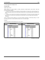
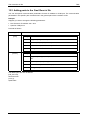
Select device... selection 5 – NMS address
If you want to open a TMA session on a device, you have to specify the address of the device. You can
apply three types of addressing methods:
Address type
relative
Description
This type of addressing is meant for a network topology where the modems are
connected in-line on management level. E.g. with extended management links
between two modems. An extended management link is realised with a cross
connect cable between the auxiliary connectors of two modems.
extended
link
PC running relative 0
TMA
relative 2
relative 1
relative 3
To enable relative addressing, no address has to be specified in the modem.
absolute
This type of addressing is meant for a network topology where the modems are not
connected in-line on management level. E.g. when there is a digital multipoint device
present.
digital
multipoint
PC running example:
TMA
absolute 0
example:
absolute 1
example:
absolute 10
example:
absolute 20
example:
absolute 30
To enable absolute addressing, an address has to be specified in the modem. The
absolute addressing range goes from 0 up to 65535. Refer to the user manual of the
modem for more information.
relative and
absolute
Relative and absolute addressing can be mixed. E.g. use relative addressing for the
modems which are connected in-line. Use absolute addressing for the modems
located after a digital multipoint device.
digital
multipoint
PC running relative 0
TMA
User manual
relative 1
example:
absolute 1
example:
absolute 2
example:
absolute 3
53
Opening a TMA session
TMA
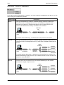
Select device... selection 6 – Exitport
If a device has more than one possible way to pass through it to another device, the Exitport drop down
box is activated. The values displayed in the box vary, depending to which device you are connected to.
Examples:
For a device that has only one exit port, the drop down box is not activated.
In that case , the only possible selection is displayed in grey.
For a device with several exit ports, the drop down box is activated. For
instance, for a modem Card Version with more than one modem on the
card (e.g. Crocus HDSL CV Twin, Crocus FO10M CV Twin, …), the drop
down box may appear as follows:
For a management concentrator, the drop down box looks as follows:
Continued on next page
54
User manual
TMA
Opening a TMA session
Select device... selection 6 – Exitport (continued)
The different Exitport values are explained in the following table:
Exit port
line x
Description
Some Telindus devices incorporate several devices on one card. This is called a
multi-device. The different devices on a multi-device are referred to using A, B,
C, D, etc.
Examples of multi-devices are:
• Crocus SHDSL CV Twin: incorporates 2 SHDSL modems on one card.
• Crocus 2M CNV CV Twin: incorporates 2 interface converters on one card.
• Crocus SDSL CV Quad: incorporates 4 SDSL modems on one card.
Such multi-devices consequently have several different exit ports. Actually, they
have as many exit ports as there are devices on the card.
Example:
Suppose you have a Crocus SDSL Twin (this is a Card Version with two SDSL
modems on it). You want to connect to the remote counterpart of the Crocus
SDSL Twin modem B, which is Crocus SDSL TT (2). In that case select in the
Exitport drop down box: Exitport ! line B.
The following figure clarifies this:
PC running
TMA
modem A
Crocus SDSL TT (1)
modem B
Crocus SDSL TT (2)
Crocus SDSL Twin
Continued on next page
User manual
55
Opening a TMA session
TMA
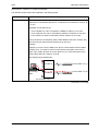
Select device... selection 6 – Exitport (continued)
Exit port
port x
Description
If you want to address a device connected to one of the asynchronous ports of a
management concentrator, you have to specify to which asynchronous port it is
connected.
Example:
The Orchid 1003 LAN TT has 14 asynchronous ports located at the back. You
can connect the control port of a Telindus device to one of these ports.
Table Top Orchid
Port 1 … 14
Table Top modem
For more information on connections to a management concentrator, refer to the
user manual of the management concentrator.
Continued on next page
56
User manual
TMA
Opening a TMA session
Select device... selection 6 – Exitport (continued)
Exit port
hardware address
(HWA)
Description
If you want to address a Card Version device which is located in a CN4 card
nest, you have to specify the hardware address. This address consists of three
fields, separated with a dot:
Field
Description
1. rack address
The rack address can be set by means of DIP switches
located at the back of the card nest. The address range
goes from 0 to 6.
Check the rack address of the card nest containing the
Card Version modem you want to address. Enter it in
the first field. For example: 2.
2. card position
Also the position of the card in the card nest has to be
known for addressing purposes. The card slot range
goes from 0 up to 14.
Check the position of the card in the card nest. Enter it
in the second field. For example: 12.
3. modem
If you want to address a certain device on a multidevice, you have to specify which device you want to
address: device A, B, C or D.
Verify which device you want to address. Enter it in the
third field. For example: B.
For more information on the card nest address and card position, refer to the
user manual of the CN4 card nest.
User manual
57
Opening a TMA session
TMA
Select device... selection 7 – Non configured device
This selection is only visible when connecting to a management concentrator that supports this feature.
Make this selection if you want to open a TMA session on a device (Card Version) which is inserted in a
CN4 card nest connected to a management concentrator through the CN4 its high-speed bus, but which
is not (yet) configured in the object table of the management concentrator. For more information the
object table, refer to Section 3.4 - Proxied IP connection to a non-IP device and the user manual of the
management concentrator.
Now specify the hardware address of the device you want to access with TMA. This is of the same form
as the hardware address (HWA) in the Exitport drop down box:
• field 1: rack address (ranges from 0 up to 6)
• field 2: card position (ranges from 0 up to 14)
• field 3: modem (ranges from A up to D).
Refer to the explanation of hardware address in the Paragraph Select device... selection 6 – Exitport.
58
User manual
TMA
Opening a TMA session
Select device... selection 8 – Password
Enter here the device its password. This is the password of the Telindus device on which you want to
open a TMA session.
If you enter nothing in this field, the previously entered network password is taken as device password
(see below for more information on these two passwords). If no password is specified in the Telindus
device, anything may be entered in the device password field.
A Telindus device which is used for the first time has no password.
Continued on next page
User manual
59
Opening a TMA session
TMA
Select device... selection 8 – Password (continued)
As you can see, there are two different passwords located on two different levels:
• the network password: in order to connect to your network through a Telindus device
• the device password: in order to open a TMA session on a Telindus device.
Some examples of combinations of network and device passwords are given below:
Example
Description
1
It is possible that the device through which you connect to the network is the device on
which you want to open a TMA session. In that case you only have to enter the network
password. The device password field can be left blank.
network password: 12345
device password: <blank>
PC running
TMA
2
modem password:
12345
It is possible that the device through which you connect to the network has the same
password as the device on which you want to open a TMA session. In that case you only
have to enter the network password. The device password field can be left blank.
network password:
12345
PC running
TMA
3
modem password:
12345
device password:
<blank>
modem password:
12345
It is possible that the device through which you connect to the network has a different
password than the device on which you want to open a TMA session. In that case you
both have to enter network and device password.
network password:
12345
PC running
TMA
modem password:
12345
device password:
67890
modem password:
67890
When you connect to a device over IP, i.e. by entering its IP address in the Connect… Device… window,
you only have to enter the device password. This because you immediately open a TMA session on the
device itself.
There are some exceptions. The Crocus Router and Orchid 1003 LAN, for instance. This because with
these devices you still have the possibility to connect on the device, or after the device.
60
User manual
TMA
Opening a TMA session
4.4 The TMA command line
The three previous sections explained how to open a TMA session on a device using the TMA graphical
user interface. However, it is possible to start TMA from the command line. This section explains how you
can do this. But before you can actually start TMA from the command line, you have to do some
preparatory work.
The following table gives an overview of this section.
Section
Title
Page
4.4.1
Before starting TMA from the command line
62
4.4.2
Displaying the TMA command line help
63
4.4.3
Starting TMA from the command line
64
4.4.4
Creating TMA command line shortcuts
65
User manual
61
Opening a TMA session
TMA
4.4.1 Before starting TMA from the command line
To start TMA from the command line, you have to use aliases. When you install TMA for the first time, no
aliases are present. This means you have to create them.
The following procedure explains how to create aliases:
Step
62
Action
1
Start the TMA application as explained in Section 4.1 - Starting TMA.
2
Connect to a device as explained in Section 4.2 - Connecting to a device.
3
Select a device as explained in Section 4.3 - Selecting a device.
4
Create an alias (e.g. Test device) for this device as explained in Section 6.2.1 - The
Connect menu, Paragraph b) Creating aliases on page 79.
5
Now you are ready to start TMA from the command line.
User manual
TMA
Opening a TMA session
4.4.2 Displaying the TMA command line help
In order to display the different TMA command line possibilities, open a DOS window and type tma –h.
The following is returned:
Important remarks
• If the alias name or password contains characters that conflict with the normal DOS syntax (such as a
comma, a space, an equal sign, etc.), then you have to surround the alias by a set of double quote
characters: “ ”.
• Neither the TMA command nor the alias name are case sensitive.
• If you want to execute the TMA command in a directory different from the TMA\bin directory (typically
C:\Program Files\TMA\bin), then make sure you define the correct path to the TMA executable on
your system.
On Windows 95 and 98 this is typically done with the set path command in the autoexec.bat file.
On Windows NT 4.0 and 2000 this is typically done with the path string in the Environment tab of the
System Properties window.
User manual
63
Opening a TMA session
TMA
4.4.3 Starting TMA from the command line
The following table lists and explains the different TMA command line possibilities:
Command
Description
tma
Starts the TMA application. You still have to fill in the Connect windows (as
described in Section 4.2 - Connecting to a device and Section 4.3 - Selecting a
device).
tma -h
Displays the TMA command line help (refer to Section 4.4.2 - Displaying the TMA
command line help).
tma alias
Connects you to the device for which this alias was created. Use this command
when no password is defined in the device.
Example
Suppose you created for a certain device the alias Test device. Suppose no
password is defined in this device. In this case, the command syntax is:
tma ″test device″
tma alias
netpw
Connects you to the device for which this alias was created. Use this command
when the network password and the device password are the same. For more
information on passwords, refer to Section 4.3.3 - The Connect… – Select device…
window selections, Paragraph Select device... selection 8.
Example
Suppose you created for a certain device the alias Test device. Suppose the
password 12 - 34 is defined in this device. In this case, the command syntax is:
tma ″test device″ ″12 - 34″
tma alias
netpw devpw
Connects you to the device for which this alias was created. Use this command
when the network password differs from the device password. For more information
on passwords, refer to Section 4.3.3 - The Connect… – Select device… window
selections, Paragraph Select device... selection 8.
Example
Suppose you created for a certain device the alias Test device. Suppose the
password 12+34 is defined in this device. Suppose you connect to the network
through a device with password 56*78. In this case, the command syntax is:
tma ″test device″ ″56*78″ ″12+34″
64
User manual
TMA
Opening a TMA session
4.4.4 Creating TMA command line shortcuts
The command line syntax allows you to create shortcuts. This means that you have immediate access to
a device just by clicking on its icon on your desktop.
The following procedure explains how to create such shortcuts:
Step
1
Action
Go to the directory where the TMA executables are located.
If you did not change the default file location during the set-up, then this directory is
C:\Program Files\TMA\bin.
2
Make a shortcut of the TMA.exe file and,
for instance, place it on your desktop.
3
Display the properties of the shortcut.
4
Edit the Target: field of the Properties window as follows:
1. Before editing, the Target: field displays the following string:
"C:\Program Files\TMA\bin\TMA.exe"
2. Add the TMA command line syntax to this string:
"C:\Program Files\TMA\bin\TMA.exe" "alias" "netpw" "devpw"
Example
Suppose you created for a certain device the alias Test device. Suppose the password
12+34 is defined in this device. Suppose you connect to the network through a device
with password 56*78. In this case, the Target: field string has to edited as follows:
"C:\Program Files\TMA\bin\TMA.exe" "test device" "56*78" "12+34"
5
Rename the shortcut. E.g. Test device.
6
Double clicking on the shortcut immediately opens a TMA session on the corresponding
device.
User manual
65
Opening a TMA session – examples
TMA
5. Opening a TMA session – examples
This chapter gives two examples of how to open a TMA session. It gives the screenshots of a filled in
Connect… – Device… and Connect… – Select device… window.
The following table gives an overview of this chapter.
Section
66
Title
Page
5.1
Example 1 – a direct connection
67
5.2
Example 2 – an IP connection
68
5.3
Example 3 – a proxied IP connection
69
5.4
Example 4 – a dial-out connection
70
5.5
Some remarks on dial-out connections
71
User manual
TMA
Opening a TMA session – examples
5.1 Example 1 – a direct connection
Suppose you have a set-up as described in the figure below:
PC running TMA:
modem A:
COM port = COM2
relative address = 0
password = 123
modem B:
relative address = 1
password = access2
Suppose you want to open a TMA session on modem B. The Connect… – Device… and Connect… –
Select device… windows look as follows:
Connect… – Device… window
User manual
Connect… – Select device… window
67
Opening a TMA session – examples
TMA
5.2 Example 2 – an IP connection
Suppose you have a set-up as described in the figure below:
port 5
LAN port
PC running
TMA
TPI port
IP
Orchid 1003 LAN:
IP address = 10.0.11.5
password = 123
control port modem A:
relative address = 0
modem B:
relative address = 1
password = access2
Suppose you want to open a TMA session on modem B. In this example, both modem A and B are
configured in the object table of the Orchid 1003 LAN. However, they are not assigned an IP address. I.e.
you can not connect to the modem over a proxied IP connection. You have to connect over IP to the
Orchid first.
The Connect… – Device… and Connect… – Select device… windows look as follows:
Connect… – Device… window
68
Connect… – Select device… window
User manual
TMA
Opening a TMA session – examples
5.3 Example 3 – a proxied IP connection
Suppose you have a set-up as described in the figure below:
port 5
TPI port
LAN port
IP
Orchid 1003 LAN
PC running
TMA
control port
modem:
(proxied) IP address =
10.0.11.15
password = access2
Suppose you want to open a TMA session on the modem. In this example, the Orchid 1003 LAN acts as
an IP proxy device for the modem. I.e. the modem is configured in the object table of the Orchid 1003
LAN (IP address, exit port, etc.). For more information, refer to Section 3.4 - Proxied IP connection to a
non-IP device.
The Connect… – Device… and Connect… – Select device… windows look as follows:
Connect… – Device… window
Connect… – Select device… window
Connecting to a non-IP device over a proxied IP
connection does not bring up the Connect… –
Select device… window. This because such a
connection does not allow you to open TMA
sessions on devices behind the non-IP device in
question.
User manual
69
Opening a TMA session – examples
TMA
5.4 Example 4 – a dial-out connection
Suppose you have a set-up as described in the figure below:
built-in PSTN
modem on
COM 4
DTE interface
PSTN
PC running
TMA
PSTN modem
high speed bus
connection
Orchid 1003 LAN
control port
Card Nest:
rack address = 3
Card Version modem:
Table Top modem:
relative address = 1
password = access2
position = 5
modem = B
relative address = 0
password = 123
Suppose you want to open a TMA session on the Table Top modem. The Connect… – Device… and
Connect… – Select device… windows look as follows:
Connect… – Device… window
70
Connect… – Select device… window
User manual
TMA
Opening a TMA session – examples
5.5 Some remarks on dial-out connections
This section gives some remarks on dial-out connections. More particular on the speed of the connection
negotiated by the two PSTN modems. Also the data format is important. Also connection messages such
as ring and echo off must be turned off.
The following table gives an overview of this section.
Section
Title
Page
5.5.1
Adding AT commands to the Tel nr field
72
5.5.2
Speed, data format and connection messages
73
User manual
71
Opening a TMA session – examples
TMA
5.5.1 Adding AT commands to the Tel nr field
Consider the example in Section 5.4 - Example 4 – a dial-out connection. In the Tel nr field of the
Connect… – Device… window, you can add supplementary AT commands.
Example
As default, pulse dialling is used to dial out. This because the parameter DialPrefix in the TMA.ini file has
the following value: AT&D1X4E0V0Q0, where “D” specifies pulse dialling. However it is possible to overrule
this by adding the AT command “T” before the telephone number entered in the Tel nr field. This is shown
in the following figure:
Depending on the AT command, you can place the command before or behind the telephone number.
72
User manual
TMA
Opening a TMA session – examples
5.5.2 Speed, data format and connection messages
To make sure the dial-out connection is established successfully, some parameters have to be set to a
certain value. This is explained by means of the following example.
Example
Suppose you have a set-up as shown in the figure below:
link speed negotiation
COM 1
PC running
TMA
PSTN modem 1
PSTN
DTE interface 1
PSTN modem 2
DTE interface 2
Orchid 1003 LAN
control port
Going from local side (utmost left side) to the remote side (utmost right side), the following things have to
be configured:
Interface
Parameter(s)
COM1
As default, the speed parameter for COM1 in the Cms2Serv.ini file is 9600 bps.
DTE interface 1
• Because the speed of COM1 is 9600 bps, also set the DTE interface 1 speed to
9600 bps.
• Set the data format to 8 + N.
• The AT commands on DTE interface 1 have to be:
− result codes on (ATQ0)
− short result codes (ATV0)
− echo off (ATE0).
By default this is so, because the DialPrefix parameter in the TMA.ini file is
AT&D1X4E0V0Q0.
link PSTN
modem 1 ↔ 2
The modems are not allowed to negotiate their speed, since this speed can then
differ from the COM speed, DTE interface and control port speed. Therefore, set a
fixed speed for the link (being 9600 bps).
DTE interface 2
• Because the speed of the control port is 9600 bps, also set the DTE interface 2
speed to 9600 bps.
• Set the data format to 8 + N.
• The AT commands on DTE interface 2 have to be:
− result codes off (ATQ1)
− echo off (ATE0).
You have to send these AT commands to on DTE interface 2.
Control port
There is nothing to configure on the control port. It uses a fixed speed of 9600 bps
and a data format of 8 + N.
User manual
73
The TMA window
TMA
6. The TMA window
After you have opened a TMA session on a device on the network, you are able to control the device.
This chapter explains every item of the TMA window which enables you to do this. First the different parts
of the TMA window are displayed and labelled. Then all these parts are explained one by one.
The following table gives an overview of this chapter.
Section
74
Title
Page
6.1
The TMA window structure
75
6.2
The menu bar
76
6.3
The toolbar
102
6.4
The containment tree window
104
6.5
The attribute window
105
6.6
The action window
112
6.7
The structured value window
114
6.8
The status bar
122
User manual
TMA
The TMA window
6.1 The TMA window structure
This section displays and labels the different parts of the TMA window.
The following figure shows the TMA window and labels the main parts:
The menu bar
The toolbar
The containment tree window
The attribute window
The action window
The structured value window
The status bar
User manual
75
The TMA window
TMA
6.2 The menu bar
This section describes the pull-down menus located in the menu bar. It displays the pull-down menus and
explains the underlying commandos.
The following table gives an overview of this section.
Section
Title
Page
6.2.1
The Connect menu
77
6.2.2
The Edit menu
80
6.2.3
The View menu
87
6.2.4
The Tools menu
88
6.2.5
The Help menu
101
The following figure depicts the menu bar and the underlying pull-down menus:
76
User manual
TMA
The TMA window
6.2.1 The Connect menu
The following table lists and describes all the commands of the Connect menu:
Command
Device…
Description
Use this command to connect to a device. Selecting this command brings up the
Connect… – Device… window. The shortcut key for this command is CTRL+N.
For more information refer to Section 4.2.2 - The Connect… – Device… window
selections.
Select device…
Use this command to select another device on the network you are currently
connected to. Selecting this command brings up the Connect… – Select
device… window. The shortcut key for this command is CTRL+D.
For more information refer to Section 4.3.3 - The Connect… – Select device…
window selections.
Application…
Use this command to connect to an application. For more information, refer to
Paragraph a) Connecting to an application, page 78.
Disconnect
Use this command to disconnect from the current device or application.
Reconnect
Use this command to reconnect to the current device or application.
Add Alias…
Use this command to create an alias for the current connection. Creating an
alias allows you to reconnect to the device or application without having to reenter the address parameters. The shortcut key for this command is CTRL+L.
For more information, refer to Paragraph b) Creating aliases, page 79.
1…
2…
3…
4…
These are the four most recently used aliases.
More…
This command displays the rest of the aliases. The shortcut key for this
command is CTRL+M.
Exit
This command closes the TMA application.
User manual
77
The TMA window
TMA
a) Connecting to an application
Use the Application… command to connect to an application (e.g. the Alarm Manager of TMA for HP
OpenView). Selecting this command brings up the Connect to application window:
This feature allows you to open a TMA session on, for example, the Alarm Manager of TMA for HP
OpenView and this on a machine that does not run HP OpenView.
The Connect to application window is split up in two parts. These are described in the following table:
Part
Description
Address
In the address field, enter the address of the application you want to connect to.
In case of the Alarm Manager for example, the address is 6fbf.
Host
Even if the application resides on another machine than the one you are running
TMA on, you can still connect to the application. Do this by ticking the Remote
host box, and entering the IP address of the remote machine running the
application you want to connect to.
78
User manual
TMA
The TMA window
b) Creating aliases
Use the Add Alias… command to create an alias for the currently active connection to a device or
application. Selecting this command brings up the Add Alias window:
Using an alias allows you to reconnect to the device or application without having to re-enter the address
parameters. However, for security reasons, the alias does not include the passwords. I.e. even when an
alias is selected, TMA will ask you to enter the network and / or device password.
You can find the four most recently used aliases under Connect in the menu bar. To display the rest of
the aliases, click on More… or press the shortcut key Ctrl+M. In this window the amount of aliases is
unlimited. It also gives you the possibility to remove old aliases.
User manual
79
The TMA window
TMA
6.2.2 The Edit menu
The Edit menu is not only available in the menu bar, but can also be displayed as pop-up menu. This is
done by selecting an element in the TMA window and pressing the right mouse button.
The contents of the Edit menu depends on which element is currently selected. The following paragraphs
explain how to display the different Edit menus. They also list and describe the underlying commands.
The following table gives an overview of the different Edit menus:
Figure
Click on the link below to jump to the corresponding paragraph…
Paragraph a) The containment tree Edit menu, page 81.
Paragraph b) The attribute Edit menu, page 82.
Paragraph c) The text Edit menu, page 84.
Paragraph d) The action Edit menu, page 85.
Paragraph e) The table Edit menu, page 86.
80
User manual
TMA
The TMA window
a) The containment tree Edit menu
Display this menu by selecting an object in the containment tree and pressing the right mouse button:
The following table lists and describes the underlying commands:
Command
Description
Retrieve
This command retrieves all the attribute values of the currently selected object
from the device. The shortcut key for this command is F5.
Reload
This command reloads the currently selected object from the device. If you
select the top object and perform a reload, the complete containment tree is
reloaded.
A reload is necessary when during a TMA session objects appear, disappear or
change in the containment tree. This is the case when, for instance, a V35
Nx64k interface module of a Telindus modem is replaced by a RS530 interface
module.
Delete
This command deletes a previously added child object. A child object is also
called a user instantiatable object.
For more information on user instantiatable objects, refer to Chapter 7 - User
instantiatable objects.
Add child
This command adds a child object. A child object is also called a user
instantiatable object.
For more information on user instantiatable objects, refer to Chapter 7 - User
instantiatable objects.
User manual
81
The TMA window
TMA
b) The attribute Edit menu
Display this menu by selecting an attribute in the attribute window and pressing the right mouse button:
The following table lists and describes the underlying commands:
Command
Description
Retrieve
This command retrieves the value of the currently selected attribute from the
device. The shortcut key for this command is F5.
Retrieve Recursive
Whereas the Retrieve command retrieves the value of the currently selected
attribute on the first level, the Retrieve Recursive command retrieves the value
of the currently selected attribute and all its possible sub-values.
This means that in case a table is selected in which structures and other tables
(i.e. nested tables) appear, the Retrieve Recursive command retrieves all the
values present in these structures and tables. TMA does not do this by default
as some tables can be very complex and might take a very long time to retrieve.
Modify
This command allows you to modify the value of the currently selected attribute.
The shortcut key for this command is F2.
Depending on the attribute a drop-down box appears in which you can select a
value, or a field appears in which you can enter characters.
Set To Default
This command sets the value of the currently selected attribute to its default
value.
Optional
This command clears an optional value. I.e. it clears a value which was entered
by the user, but for which it was not mandatory to enter a value. The string
<Opt> (re)appears.
Continued on next page
82
User manual
TMA
The TMA window
The attribute Edit menu (continued)
Command
Description
Set To Type
This command allows you to select a value type in case of a choice value. For
more information on choice values, refer to Section 6.5 - The attribute window,
Paragraph c) Attribute value.
Select All
This command selects all the attributes in the attribute window. The shortcut key
for this command is CTRL+A.
If you execute the Select All command and then the Set To Default command, all
the attributes in the attribute window are selected and their values are reset to
their default value.
When selecting an attribute which is present in a structure or table, one extra command is listed:
Set To This Choice Type.
Also this command allows you to select a value type in case of a choice value. For more information on
choice values, refer to Section 6.5 - The attribute window, Paragraph c) Attribute value.
User manual
83
The TMA window
TMA
c) The text Edit menu
Display this menu by selecting an attribute in the attribute window, performing the Modify command and
pressing the right mouse button:
This Edit menu does not appear for all attribute values. Only for those values where characters have to
be edited.
The following table lists and describes the underlying commands:
Command
Description
Undo
Cancels the previous action.
Cut
Removes the current selection. This selection is placed in the clipboard and
therefore can be paste somewhere else.
Copy
Copies the current selection to the clipboard.
Paste
Places the current contents of the clipboard.
Delete
Removes the current selection. This selection is not placed in the clipboard.
Select All
Selects the entire string.
84
User manual
TMA
The TMA window
d) The action Edit menu
Display this menu by selecting an action in the action window and pressing the right mouse button:
The following table lists and describes the underlying commands:
Command
Execute
Description
This command executes an action.
For some actions you first have to set an argument value before you can
execute the action.
Modify
This command allows you to modify the argument value of the currently selected
action. A drop-down box appears in which you can select a value. The shortcut
key for this command is F2.
Set To Default
This command sets the argument value of the currently selected action to its
default value.
Set To Type
This command allows you to select a value type in case of a choice value. For
more information on choice values, refer to Section 6.5 - The attribute window,
Paragraph c) Attribute value.
User manual
85
The TMA window
TMA
e) The table Edit menu
Display this menu by selecting an attribute which has <Table> as value and pressing the right mouse
button in the structured value window:
This Edit menu does not appear for all structured values. Only for those values where the attribute is
followed by the string <Table>.
The following table lists and describes the underlying commands:
Command
Description
Set To Default
This command sets the currently selected value to its default value.
Insert Row Before
This command inserts a row before the currently selected row.
Insert Row After
This command inserts a row after the currently selected row.
Delete Row
This command deletes an entire row.
Select All
This command selects all the values in the structured value window. The
shortcut key for this command is CTRL+A.
If you execute the Select All command and then the Set To Default command, all
the values in the structured value window are selected and are reset to their
default value.
86
User manual
TMA
The TMA window
6.2.3 The View menu
The following table lists and describes all the commands of the View menu:
Command
Description
ToolBar
Toggling this command displays or hides the toolbar.
StatusBar
Toggling this command displays or hides the status bar.
StructuredValues
Toggling this command displays or hides the structured value window.
Advanced
Toggling this command displays or hides the advanced attributes.
Subsystem Picture
This command displays the sub-system picture. The shortcut key for this
command is CTRL+P.
The sub-system picture is a TMA tool which visualises the status information of
the device. The front panel LED indications of the sub-system picture are the
same as those of the device. The sub-system picture also displays the status of
the front panel test buttons (if present), the interface connection, the line
connection, etc.
For more information on the sub-system picture of the Telindus device, refer to
its user manual.
User manual
87
The TMA window
TMA
6.2.4 The Tools menu
The following table lists and describes all the commands of the Tools menu:
Command
Export…
Description
This command enables you to export configuration, status, performance and
alarm information towards a file. Selecting this command brings up the Export
configuration parameters window.
Refer to Paragraph a) The Export configuration parameters window selections,
page 89.
Import…
This command enables you to import configuration information from a file.
Selecting this command brings up the Import configuration window.
Refer to Paragraph b) The Import configuration window selections, page 97.
Download…
This command enables you to download new firmware to the device. Because
this is quite an important feature, it is discussed in a separate section.
Refer to Chapter 10 – Downloading software.
Options…
This command enables you to set display and upload options.
Refer to Paragraph c) The Options window selection, page 99.
88
User manual
TMA
The TMA window
a) The Export configuration parameters window selections
This section shows the Export configuration parameters window. All the different selection possibilities
are numbered. They are explained in the following paragraphs.
The Export configuration parameters window is depicted below:
Export selection 1
Export selection 2
Export selection 3
Export selection 4
Export selection 5
Export selection 6
Export selection 7
Export selection 8
User manual
89
The TMA window
TMA
Export selection 1 - Save in
Choose here the location for the export file. As default, the file is saved in the TMA\bin directory.
Export selection 2 - File name
Enter here the name of the export file. It is not necessary to enter the file extension, it is added
automatically.
90
User manual
TMA
The TMA window
Export selection 3 - Save as type
Choose here the type of the export file. The table below shows the different file types:
File
type
Can be used to
export the …
CMS
configuration
attributes
You can export the configuration attributes of a Telindus device to a CMS
file. This means that the configuration attribute settings are saved in a file.
Later, you can import this configuration in the same or another device.
This is particularly interesting when a lot of devices need the same
configuration.
TXT
• configuration
• status
• alarm
You can export the configuration, status and alarm attributes to a plain
text file. This is particularly interesting for documentation purposes.
… attributes
CLI
configuration
attributes
Description
In contrast with the configuration attributes, the status and alarm attributes
can only be exported to a TXT file.
You can export the configuration attributes of a Telindus device to a CLI
file. Analogue to the CMS file, this allows you to distribute configuration
files amongst several devices. Some advantages of using a CLI file are:
• you can still edit the file using the CLI syntax.
• you can use the file when running CLI on the devices themselves
(through a terminal or Telnet session).
• you can use the file when running TMA CLI on your computer.
Important remarks
• The purpose of the CLI import is to distribute configurations. Not to run
scripts as in CLI or TMA CLI.
• When you edit the CLI file yourself, make sure that you never use the
commands disconnect and exit. This closes the CLI core and gives
unexpected results.
CSV
performance
attributes
You can export the performance attributes to a text file. This is particularly
interesting for documentation purposes.
In contrast with the TXT file, the CSV file is not a plain text file. It is a
comma separated value file. This because performance information
consists of a lot of tables which could result in a very complex text file. A
CSV file has the advantage that it can be easily imported in a spreadsheet
or database for further processing.
User manual
91
The TMA window
TMA
Export selection 4 - Append
Tick this box if you want to add the data you are about to export to an existing export file. The new export
data is inserted at the end of the file.
92
User manual
TMA
The TMA window
Export selection 5 - Full configuration
This selection is only available when you export the configuration attributes.
When exporting to a …
• TXT file, tick this box if you want to export all the configuration attributes instead of only the
configuration attributes of the currently selected object.
• CMS or CLI file, things are a bit different than for a TXT file. In this case, a load default configuration
action is inserted at the beginning of the file. Then, only those attributes which have a different value
than the default value are stored in the file. This results in a compact file.
When you want a CMS or CLI file with the complete configuration (instead of only the non-default
configuration), then proceed as follows:
Step
Action
1
In the containment tree window, select the
top object:
2
In the attribute window, select the
Configuration tab:
3
In the Tools menu, select Export…
Figure
The Export configuration parameters
window appears.
4
Tick the All attributes of <top object> and
Recurse submodules selection.
5
Enter a file name, a destination and press
on the Save button.
User manual
93
The TMA window
TMA
Export selection 6 - Selected attributes
Tick this selection if you only want to export the attributes you selected in the attribute window.
Example:
Suppose you only want to export the h2Modem and h24Modem performance attributes of a Crocus SDSL
modem. Proceed as follows:
Step
Action
1
In the containment tree window, select the
modem object:
2
In the attribute window, select the
Performance tab:
3
Hold the CTRL-key down and select the
h2Modem and h24Modem attributes in the
attribute window:
Figure
Release the CTRL-key.
4
In the Tools menu, select Export…
In the Export configuration parameters
window, the Selected attributes selection is
automatically ticked. Enter a file name, a
destination and press on the Save button.
94
User manual
TMA
The TMA window
Export selection 7 - All attributes of <object>
You don’t necessarily have to export the complete configuration of a device. You are able to export the
configuration attribute settings of one object only.
Example:
Suppose you only want to export the configuration attributes of the line object of a Crocus SDSL modem.
Proceed as follows:
Step
Action
1
In the containment tree window, select the
line object:
2
In the attribute window, select the
Configuration tab:
3
In the Tools menu, select Export…
Figure
The Export configuration parameters
window appears.
4
Tick the All attributes of line selection.
5
Enter a file name, a destination and press
on the Save button.
User manual
95
The TMA window
TMA
Export selection 8 - Recurse submodules
Tick this selection if you want to export the attributes of the currently selected object and the attributes of
the underlying objects.
Example:
In most Telindus modems the modem object has one or more underlying line objects. To export the
attributes of the modem object together with the attributes of the line object(s), proceed as follows:
Step
Action
1
In the containment tree window, select the modem object.
2
In the attribute window, select one of the tabs (depending on which type of attribute you
want to export).
3
In the Tools menu, select Export…
The Export configuration parameters window appears.
96
4
In the Export configuration parameters window, tick the Recurse submodels selection.
5
In the Export configuration parameters window, enter a file name, a destination and
press on the Save button.
User manual
TMA
The TMA window
b) The Import configuration window selections
This section shows the Import configuration window. All the different selection possibilities are numbered.
They are explained in the following paragraphs.
The Import configuration window is depicted below:
Import selection 1
Import selection 2
Import selection 3
User manual
97
The TMA window
TMA
Import selection 1 - Look in
Locate with this selection the file you want to import.
Import selection 2 - File name
Enter here the name of the file you want to import.
Import selection 3 - Files of type
Select whether the file you want to import is a CMS or a CLI file. For more information on these file types,
refer to Paragraph Export selection 3 - Save as type, on page 91.
After importing a configuration file, you still have to activate the configuration. Do this by pressing the
Send all attributes to device button:
98
User manual
TMA
The TMA window
c) The Options window selection
This section shows the two Options windows. All the different selection possibilities are numbered. They
are explained in the following paragraphs.
The Options - Display window is depicted below:
Options selection 1
The Options – Auto Upload window is depicted below:
Options selection 2
Options selection 3
User manual
99
The TMA window
TMA
Options selection 1 - Use automatic column resizing in list controls
Tick this box if you want that the columns in the TMA window are automatically resized to fit the displayed
strings.
Options selection 2 - Period
Here, you can specify the upload period for the status, performance and alarm attributes. E.g. a period of
1x10 sec means that every 10 seconds TMA will retrieve the values of the status, performance and alarm
attributes from the device.
Options selection 3 - Auto upload readonly attributes
If this box is ticked, the status, performance and alarm attributes are automatically retrieved from the
device with an interval as specified in Options selection 2 - Period.
If this box is not ticked, the status, performance and alarm attributes are not automatically retrieved from
the device.
Only the read-only attributes (status, performance and alarm) are retrieved automatically from the device.
The configuration attributes are not retrieved automatically.
100
User manual
TMA
The TMA window
6.2.5 The Help menu
About… displays version information of TMA. An example of an About TMA window is given below:
Model… displays version information of the model files. An example of an About model files window is
given below:
User manual
101
The TMA window
TMA
6.3 The toolbar
This section describes the icons located in the toolbar. It displays the icons and explains their function.
The toolbar contains the most important TMA commandos represented as icons. This enables quick
access to these commands. The following table lists the icons:
Icon
Name
Connect to device
Function
Press this button to connect to a device. Pressing this button
brings up the Connect… – Device… window.
For more information refer to Section 4.2.2 - The Connect… –
Device… window selections.
Disconnect from
device or application
Press this button to disconnect from the current device or
application.
Select device
Press this button to select another device on the network you are
currently connected to. Pressing this button brings up the
Connect… – Select device… window.
For more information refer to Section 4.3.3 - The Connect… –
Select device… window selections.
Reconnect to device
or application
Press this button to reconnect to the current device or application.
Send all attributes to
device
Press this button to send the configuration attributes to the device.
Retrieve all attributes
from device
Press this button to retrieve all the attributes from the device.
Export data to file
If you made changes in the configuration of the device, press the
Send all attributes to device button. It sends the new configuration
to the device and this configuration is then activated.
Provided that the upload functionality is activated, the read-only
attributes (status, performance and alarms) are automatically
retrieved from the device. This is not so for the configuration
attributes. Pressing the Retrieve all attributes from device button
however, retrieves all attributes from the device.
Press this button to export data to a file. Pressing this button
brings up the Export configuration parameters window.
For more information refer to Section 6.2.4 - The Tools menu.
Import data from file
Press this button to import data from a file. Pressing this button
brings up the Import configuration window.
For more information refer to Section 6.2.4 - The Tools menu.
Continued on next page
102
User manual
TMA
The TMA window
The toolbar (continued)
Icon
Name
Switch to basic /
advanced view
Function
Toggling this button displays or hides the advanced configuration
parameters.
Hiding the advanced configuration parameters might be useful
when you first start using the device. It makes the configuration
attributes overview less complex. It also shows you only those
configuration attributes which are really necessary to establish a
basic connection.
Sub-system picture
Press this button to display the sub-system picture of the device.
For more information refer to Section 6.2.3 - The View menu.
Cancel all pending
requests
Press this button to cancel all requests that are currently pending.
When you browse through the containment tree of a device, it
sometimes can take a while before all attribute values of the
current object are retrieved from the device (this is especially true
when the Performance group is selected, and even more so when
connected to a remote device).
If, for some reason, you prematurely want to cancel the retrieving
of the attribute values, then press the Cancel all pending requests
button.
User manual
103
The TMA window
TMA
6.4 The containment tree window
This section describes the containment tree window. It displays the containment tree and explains what it
contains. It also shows how to navigate in this window.
The following figure shows the containment tree window:
Containment tree
Object
Node
a) Containment tree
What is a containment tree?
The containment tree represents the hierarchical structure of the Telindus device. It is composed of a
number of objects that are ordered in a tree. This tree resembles a Windows directory structure:
• it is also a levelled structure, with nodes which can be expanded or reduced
• the containment tree objects can be compared with file folders
• the objects contain attributes like file folders contain files.
b) Object
What is an object?
An object represents a physical interface, an application or a combination of both. Each object has its
own set of attributes.
Example:
The top object crocusSDSL contains the sub object modem. On its turn, the sub object modem contains the
sub object line. This object contains all the attributes concerning the line pair. E.g. the status attribute
lineAttenuation(dB).
c) Node
How to navigate in the containment tree?
In the containment tree window you can:
• click on the nodes to expand or reduce the containment tree or parts of it.
• select an object in the containment tree. The corresponding attributes are displayed in the attribute
window.
104
User manual
TMA
The TMA window
6.5 The attribute window
This section describes the attribute window. It explains what an attribute is and shows the different
attribute value types. It also explains the difference between the configuration, status, performance and
alarm attributes.
The following figure shows the attribute window:
Attribute position
Attribute group
Attribute
Attribute value
Attribute status
a) Attribute
What is an attribute?
An attribute is a parameter which is related to a certain object. It has a certain value which:
• can be changed in case of a configuration attribute (provided you have write access)
• is read-only in case of a status, performance and alarm attribute.
Example:
The object modem contains the configuration attribute channel. Its value can be set to central or to remote.
b) Attribute position
Here you can see the position of the attribute in the containment tree.
Example:
If the attribute position displays CrocusSDSLTT/modem/line: it means that the attribute window currently
displays the attributes of the line object, which is part of the modem object, which is part of the top object
CrocusSDSLTT.
User manual
105
The TMA window
TMA
c) Attribute value
What is an attribute value?
An attribute value is located behind the attribute name. Basically, there are two different value types:
• a simple value: this is a value which is displayed in the attribute window.
• a structured value: this is a list of values which is displayed in the structured value window.
Simple value
A simple value is displayed in the attribute window. The following table gives some examples of simple
values:
Simple value
direct editable
Description
This simple value can be edited immediately in the
attribute window. When you click on it, a cursor appears
and you can enter your value.
There are no underlying values in a drop-down box or in the structured value
window.
drop-down box
This simple value is selected from a drop-down box.
Only configuration attributes can have drop-down box
selectable values.
bit string
This simple value gives a bit string representation of the
underlying values (e.g. 101). These underlying values are
visible in the structured value window. They can only
adopt two different states:
• 1 : enabled or on
• 0 : disabled or off.
The bit string is a special case of a simple value. It does
have underlying values which are visible in the
structured value window, but only to increase readability
and clarity. The real value, i.e. the bit string itself, is
visible in the attribute window.
direct editable
bit string
This is a special case of a bit string. In this case, there are no underlying values in
the structured value window. Instead, this bit string is edited by …
• clicking on the bit string in order to select it,
• dragging the mouse pointer over the bit string.
By doing so, you can make the separate bits …
• bold, which represents a 1 (enabled or on).
• greyed out, which represents a 0 (disabled or off).
In the following example, the bits 0 up to 16 are set to 1:
Continued on next page
106
User manual
TMA
The TMA window
Attribute value (continued)
Structured value
A structured value is a list of values which is displayed in the structured value window. In the attribute
window they are represented as the strings <Struct> or <Table>. The following table displays these
structured values:
Structured
value
Description
structure
The <Struct> string indicates that there are underlying
values. These underlying values are visible in the
structured value window. They are located next to
each other, i.e. in one row.
table
The <Table> string indicates that there are underlying
values. These underlying values are visible in the
structured value window. They are placed in rows and
columns.
Continued on next page
User manual
107
The TMA window
TMA
Attribute value (continued)
Choice value
A choice value is a value which has two or more possible value types. In other words, you first have to
make a “pre-selection” which determines the value type (e.g. direct editable, drop-down box, bit string,
structured value, etc.) and then you can edit the value itself. The following example clarifies this.
Suppose you have an attribute bandwidth for which, depending on the application, you have to specify a
speed or timeslots. So, you first make a selection between the choice value speed or timeslots. In case you
select the choice value …
• speed then you get, for example, a direct editable value in which the default of 128 (kbps) appears. You
can change the value by editing the direct editable value.
• timeslots then you get, for example, a direct editable bit string in which all bits are selected by default.
You can change the value by editing the direct editable value.
Because editing a choice value is somewhat more complicated than editing other values, it is explained
thoroughly below.
Suppose you have an attribute bandwidth, which is present in a table. This attribute has a choice value.
Edit this attribute as follows:
• select the choice value ! click the right mouse button ! select Modify ! select a value type from the
drop-down box ! edit the resulting value type
• select the choice value ! press the keyboard key F2 ! select a value type
from the drop-down box ! edit the resulting value type
• double click on the choice value ! select a value type from the drop-down
box ! edit the resulting value type
• select the choice value ! press the right mouse
button ! select Set To Type ! select a value type
from the drop-down box ! edit the resulting value
type
• expand the choice value ! select a value type in the expanded
structure ! press the right mouse button ! select Set To This
Choice Type ! edit the resulting value type
Continued on next page
108
User manual
TMA
The TMA window
Attribute value (continued)
How to edit a configuration attribute value?
If you have write access to the device, you are able to edit the configuration of the device. To edit a
configuration attribute value, either:
• select the value ! click the right mouse button ! select Modify
or
• select the value ! press the keyboard key F2
or
• double click the left mouse button on the value.
User manual
109
The TMA window
TMA
d) Attribute status
What do the coloured symbols in front of an attribute mean?
The coloured symbols in front of an attribute reflect the status of the attribute. The following table clarifies
this:
Symbol
Description
The attribute is a configuration attribute and can be modified. I.e. you have write access to
the device.
The value of the configuration attribute has been changed, but has not yet been sent to
the device. To send and activate the new configuration, press the Send all attributes to
device button:
The attribute is read-only. This means the attribute is:
• a status, performance or alarm attribute
• a configuration attribute, but you have no write access to the device (only read
access).
The attribute is being retrieved from or send to the device.
110
User manual
TMA
The TMA window
e) Attribute group
What is an attribute group?
An attribute group assembles a set of attributes related by functionality. There are four attribute groups in
TMA, which correspond with the four tabs in the attribute window:
Group
configuration
Description
In this group all the configuration attributes of the device can be found. Use
these to configure the device to accommodate your needs.
E.g. retrain in the modem object, speed in the line object, clocking in the <interface>
object, etc.
status
This group displays the status of the device, i.e. its current situation. Should a
problem occur, you can immediately check several status attributes to locate the
problem.
E.g. errorCount in the modem object, noiseMargin in the line object, ifOperStatus in the
<interface> object, etc.
performance
This group gives a history of the device its performance. This information allows
you, for instance, to trace bottlenecks in the network, to determine overall
network performance, etc.
E.g. h2Modem in the modem object, h2BitError or h24LineParameters in the line object,
etc.
alarms
This group displays the device alarms which are currently active. As the status
attributes, the alarm attributes enable you to locate a problem quickly.
E.g. SyncLoss in the modem object, LinkDown in the line object, etc.
User manual
111
The TMA window
TMA
6.6 The action window
This section describes the action window. It explains what an action is and shows the different action
types.
The following figure shows the action window:
Action
Execute action
a) Action
What is an action?
An action is an executable parameter which causes the device to do something. E.g. Cold Boot, Load Default
Configuration, Test Activation, etc.
The actions are not always visible in the action window. They are assigned to a combination of a group
with an object.
Example:
If you select the top object (e.g. CrocusSDSLTT) and the group Configuration, then the action window displays
the following actions:
•
•
•
•
Activate Configuration
Load Saved Configuration
Load Default Configuration
Cold Boot.
If you select the object modem and the group Performance, then the action window displays the following
actions:
• Test Activation
• Force Full Retrain.
112
User manual
TMA
The TMA window
b) Execute action
How to execute an action?
Actions can have an argument value or not. This has an impact on how to execute the action. The
following table clarifies this:
Action
without an
argument value
Description
In this case, no argument values have to
be selected. I.e. you can immediately
execute this action.
To execute this action, either:
• select the action ! click the right mouse button ! select Execute
or
• double click the left mouse button on the action.
with an
argument value
Before executing this action,
you have to select an
argument value. Then you
can execute the action.
As an attribute value, an
argument value can be a
simple or a structured value.
To execute this action, either:
• select an argument value ! select the action ! click the right mouse button !
select Execute
or
• select an argument value ! double click the left mouse button on the action.
User manual
113
The TMA window
TMA
6.7 The structured value window
This section describes the structured value window. It explains what a structured value is and shows how
to navigate in this window.
The following figure shows the different components of a structured value window:
Bit string, <Struct>, <Table>
Add / delete row tools
Filter tool
Sort, expand and collapse tools
Structured value
Navigation tool
Sub value
a) Structured value
What is a structured value?
Some attribute values contain underlying values. These underlying values are called a structured value.
These values are displayed in the structured value window.
Example:
The configuration attribute security has a structured value which contains the device passwords, the
performance attribute lineParameters has a structured value which contains line status information, etc.
b) Bit string, <Struct>, <Table>
How to determine which attribute has a structured value?
When a bit string (e.g. 101) or the string <Struct> or <Table> is displayed in the value field of an attribute, it
means that it has a structured value. Selecting this string will reveal the underlying values in the
structured value window.
For more information on these structured value types, refer to Section 6.5 - The attribute window,
Paragraph c) Attribute value.
114
User manual
TMA
The TMA window
c) Add / delete row tools
How to add or delete rows in a table?
Some configuration attributes have a table as structured value. In this table you can filter, add or delete
rows. This is done with the structured value tools. The following table shows these tools:
Tool
Name
Insert row before
Function
Inserts a row before the current selected row.
To insert a row, proceed as follows:
• if there are no rows in the table yet: just press the Insert row
before button
• if there are already rows in the table: select the entire row by
clicking on the blue triangle ! press the Insert row before
button.
Insert row after
Inserts a row after the current selected row.
To insert a row, proceed as follows:
• if there are no rows in the table yet: just press the Insert row
after button
• if there are already rows in the table: select the entire row by
clicking on the blue triangle ! press the Insert row after
button.
Delete row
Deletes an entire row.
To delete a row, select the entire row by clicking on the blue
triangle ! press the Delete row button.
User manual
115
The TMA window
TMA
d) Filter tool
What does the filter tool do?
The filter tool allows you to filter out rows from a table. For example, in very long and complex tables, it is
very useful when you can filter out only those rows that are of interest to you.
How to filter rows from a table?
In order to filter rows from a table, proceed as follows:
Step
1
Action
Click on the filter button:
⇒ An empty row appears at the top of the table.
2
In this empty row you can specify the filter criteria. As soon as a criterion is entered, the
row(s) that meet(s) this criterion is/are filtered.
Example:
The different filter criteria are given below.
3
To undo the filtering, just press the filter button again.
⇒ The table is displayed completely again.
Continued on next page
116
User manual
TMA
The TMA window
Filter tool (continued)
What are the possible filter criteria?
It is possible to filter on character strings, integers, enumerated values and IP addresses:
Filter criteria
character
string
Description
Either you enter the exact character string, or you use the * character as wildcard.
The latter allows you to filter on parts of a character string.
Example:
Before filtering
After (character + wildcard) filtering
Filtering on character strings is case sensitive.
integer
Enter the integer based upon which you want to filter. You cannot use a wildcard.
enumerated
value
Select a value from the drop down box.
IP address
Enter the IP address based upon which you want to filter. You cannot use a wildcard.
I.e. you have to enter the complete, exact IP address.
User manual
Example:
117
The TMA window
TMA
e) Sort, expand and collapse tools
Sorting a table
What is the sort tool?
When clicking on a column header in a table, the table is sorted based on that column. When the
following indication appears …
• !, then the column (and hence the table) is sorted ascending. This means the entries that begin with
special characters come first, then those with numbers (from 0 to 9) and finally those with letters (from
a to z).
• ", then the column (and hence the table) is sorted descending. This means the entries that begin with
letters (from z to a) come first, then those with numbers (from 9 to 0) and finally those with special
characters.
Just by clicking the column header you can switch between ascending or descending sorting. To undo
the sorting, just click on another attribute and then click on the table again.
Example:
The following table is sorted based on the “name“ column:
Sorted ascending
Sorted descending
Continued on next page
118
User manual
TMA
The TMA window
Sort, expand and collapse tools (continued)
Expanding and collapsing structures
What is the expand and collapse tool?
Some tables contain structures. You can enter these structures by double-clicking on the <Struct> string.
The structured value window then displays the structure. However, the expand tool allows you to expand
such a structure in such a way that it becomes a part of the table. The following example clarifies this:
You can …
which …
double-click on the
<Struct> string,
displays the structure separately in the structured value window:
click on the expand
tool #,
expands the structure in such a way that it becomes a part of the table:
To collapse the structure again, click on the collapse tool $.
Sorting an expanded structure
You can also sort a structure that has been expanded. However, pay attention where to click in order to
sort the table or collapse the structure.
Click on the …
in order to …
upper column header,
collapse the structure.
lower column header,
sort the table based on that column.
User manual
119
The TMA window
f)
TMA
Sub value
What is a sub value?
In a structured value you can also encounter a bit, <Struct> or <Table> string. This means that there is yet
another underlying value, also called sub value.
Example:
Step
120
Action
Result
1
Select the modem
object in combination
with the Alarms tab.
The alarmInfo attribute appears in the attribute window:
2
Select the alarmInfo
attribute.
The structured value appears in the structured value window:
3
Double click the left
mouse button on the
structured value
currentAlarms.
The sub value appears in the sub value window:
User manual
TMA
The TMA window
g) Navigation tool
How to navigate in the structured value window?
The example in Paragraph f) Sub value shows how to display a sub value. Once you reach the lowest
possible level, you can move up again level by level. This is done by the One level up button, as shown in
the following figure:
User manual
121
The TMA window
TMA
6.8 The status bar
This section describes the status bar. It explains the status information which is displayed in the status
bar.
The following figure shows the status bar:
Status message
Busy indication
a) Status message
What is a status message?
A status message is a message which communicates status information to the user. Three different types
of messages are displayed in the status bar:
Message type
status message
Description
This message gives information about the status of TMA. I.e. it displays what the
application is doing.
Examples:
information
message
If you open a menu in the menu bar and place the arrow on a certain command,
a short explanation of this command appears in the status bar.
Example:
value message
If you modify a direct configuration value, the status bar displays:
• which type of value you have to enter (character string, integer, real, …)
• the value range.
Examples:
122
User manual
TMA
The TMA window
b) Busy indication
This square lights up when the application is busy. During that time you can not work in the TMA window.
I.e. you can not change groups, change an attribute value, … Once the colour disappears, TMA is
available again.
User manual
123
TMA
Reference manual
124
Reference manual
TMA
Reference manual
125
User instantiatable object
TMA
7. User instantiatable objects
This chapter explains what user instantiatable objects are. It also explains how to add and remove user
instantiatable objects.
The following table gives an overview of this chapter.
Section
126
Title
Page
7.1
What is a user instantiatable object?
127
7.2
Adding a user instantiatable object
128
7.3
Removing a user instantiatable object
129
Reference manual
TMA
User instantiatable object
7.1 What is a user instantiatable object?
On some device (e.g. the Telindus 1421 SHDSL Router) some objects are not present in the containment
tree by default. If you want to use the features associated with such an object, then you have to add the
object first. An object that can be added by the user is called a user instantiatable object. Also referred to
as a child object because it is added under a parent object.
Reference manual
127
User instantiatable object
TMA
7.2 Adding a user instantiatable object
To add a user instantiatable object to the containment tree, proceed as follows:
Step
1
Action
Left-click on the object under which you want to add a user instantiatable object. By
doing so, the object is selected (highlighted blue).
E.g. left-click the router object of the Telindus 1421 SHDSL Router.
2
While the object remains selected, right-click it.
⇒ A pop-up menu appears.
3
In the pop-up menu, select Add Child. Possibly a new menu appears in which you can
choose from several child objects. Choose a child object.
E.g. in our example, select the child object routingFilter.
⇒ The Add module window appears.
4
In the Add module window, type the name you want to appear after the child object
name. I.e. you have to type the index name, also called instance name. Then click on
OK.
E.g. in our example, type for instance filter1.
⇒ The child object is added under the parent object with the specified instance name.
The following screenshot exemplifies the procedure:
The result is:
128
Reference manual
TMA
User instantiatable object
7.3 Removing a user instantiatable object
To remove a user instantiatable object from the containment tree, proceed as follows:
Step
1
Action
Left-click the user instantiatable object you added earlier. By doing so, the object is
selected (highlighted blue).
E.g. left-click the routingFilter[filter1] object of the Telindus 1421 SHDSL Router you added
in the example of Section 7.2 - Adding a user instantiatable object.
2
While the object remains selected, right-click it.
⇒ A pop-up menu appears.
3
In the pop-up menu, select Delete.
⇒ The user instantiatable object is deleted.
The following screenshot exemplifies the procedure:
Reference manual
129
User defining values using the custom.txt file
TMA
8. User defining values using the custom.txt file
This chapter explains how you can user define values for attributes that have a string or an integer as
value. You can do this using the custom.txt file.
The following table gives an overview of this chapter.
Section
130
Title
Page
8.1
What is user defining values?
131
8.2
Creating the custom.txt file
132
8.3
The structure of the custom.txt file
133
8.4
The sections of the custom.txt file
134
8.5
The definitions of the custom.txt file
135
8.6
An example of a custom.txt file
142
8.7
Reading the custom.log file
144
Reference manual
TMA
User defining values using the custom.txt file
8.1 What is user defining values?
What is user defining values?
User defining values has two main advantages:
• You are able to predefine a set of values for a string value. Values which can then be selected from a
drop-down box instead of typing the complete string.
• You are able to give a sensible name to an otherwise very cryptic integer value.
You can only user define values for string and integer attribute values. Not for enumerated values, IP
addresses, etc. Examples of string values are the values of the attributes sysName, sysContact, sysLocation,
etc. Examples of integer values are the values of the attributes cms2Address, alarmFilter, broadcastTimer, etc.
How to user define values?
In order to user define values, you have to create and edit a custom.txt file (this file is not created when
TMA is installed).
What is the custom.txt file?
The custom.txt file is a plain text file containing special syntax which defines the values you want. This
custom.txt file is loaded and parsed when TMA starts. When an error is encountered, TMA displays an
error message and writes the error in the custom.log file.
What is the location of the custom.txt file?
You have to place the custom.txt file in the TMA\config directory (typically C:\Program Files\TMA\config).
Reference manual
131
User defining values using the custom.txt file
TMA
8.2 Creating the custom.txt file
In order to create the custom.txt file, proceed as follows:
Step
Action
1
Go to the directory TMA\config (typically C:\Program Files\TMA\config).
2
Create a new (plain) text document in this directory.
3
Rename this text document to custom.txt.
4
Open the custom.txt file and edit it with a plain text editor using the syntax as described
in Section 8.3 - The structure of the custom.txt file, Section 8.4 - The sections of the
custom.txt file and Section 8.5 - The definitions of the custom.txt file.
5
Save the custom.txt file and start TMA. If TMA starts and …
• no error message is displayed, then the custom.txt file is correct.
• the following error message is displayed:
then an error is present in the custom.txt file. Read the custom.log file to find out
more about the nature of the error. For more information, refer to Section 8.7 Reading the custom.log file.
132
Reference manual
TMA
User defining values using the custom.txt file
8.3 The structure of the custom.txt file
There are three main elements that make up the custom.txt file:
Element
section
Description
The file is divided into a number of sections. Each section consists of a section header
followed by a number of definitions.
For more information on sections, refer to Section 8.4 - The sections of the custom.txt
file.
definition
One section can contain one or several definitions. With these definitions you create
the user defined values.
For more information on definitions, refer to Section 8.5 - The definitions of the
custom.txt file.
comment
Everything that is typed after a ″#″ character is considered as comment (until the end
of the line). This allows you to add personal comments to clarify the custom.txt file.
Example
The following figure shows an example of the structure of a custom.txt file:
section
section header
comment
definition
Reference manual
133
User defining values using the custom.txt file
TMA
8.4 The sections of the custom.txt file
What is a section?
The custom.txt file is divided into a number of sections. Each section consists of a section header
followed by a number of definitions:
<section> = <section_header> { <defintition> }
Section header syntax
The syntax for the section header is:
<section_header> = ″[″ IDENTIFIER ″]″
Section types
There are two types of sections:
Section type
common
Description
This is a common section. Hence, the name of this section is ″common″.
All definitions in this section apply (if possible) to all devices.
specific
This is a device specific section. The name of this section is the name of the top object
in the containment tree of the device.
All definitions in this section apply to one specific device only.
The top object name can also be found in the
second column of the model.nms file. E.g. for a
Crocus HDSL TT this is crocusHDSLTT, for a
Crocus DXC this is crocusDXC, etc.
134
Reference manual
TMA
User defining values using the custom.txt file
8.5 The definitions of the custom.txt file
What is a definition?
One section can contain one or several definitions. With these definitions you create the user defined
values.
Definition syntax
A definition has the following global syntax:
<definition> = <attribute_specification> ″=″ <value_list> ″;″
with <attribute_specification> = <path> <attribute_name> { ″.″ <element_name> }
Definition description
A definition can span multiple lines. The end of the definition is marked with a ″;″ character. The other
elements of the definition are listed below:
Element
Description
<path>
Refer to Section 8.5.1 - The path, page 136.
<attribute_name>
Refer to Section 8.5.2 - The attribute and element name, page 139.
<element_name>
<value_list>
Reference manual
Refer to Section 8.5.3 - The value list, page 140.
135
User defining values using the custom.txt file
TMA
8.5.1 The path
What is a path?
A path specifies the way to reach a certain attribute or element through the containment tree of a device.
Path syntax
A path has the following syntax:
<absolute_path> = ″/″ { <object_name_index> ″/″ }
<relative_path> = <object_name> ″/″
with
<object_name_index> = IDENTIFIER [ ″[″ NUM | IDENTIFIER ″]″ ]
<object_name> = IDENTIFIER;
Path types
There are two types of paths:
Path
absolute
Description
An absolute path starts with a ″/″ character and specifies the full path to an object
(and so to an attribute or element).
This means the definition applies to one specific object of the containment tree.
Example
/modem/line[1]/alarmLevel.LinkDown
In this example, the definition only applies to the LinkDown element of the alarmLevel
attribute in the object line[1]. The definition does not apply to the LinkDown element in the
object line[2] or line[3].
relative
A relative path starts with the name of an object followed by a ″/″ character (and
followed by another object or an attribute or element).
This means the definition applies to every object in the containment tree with this name
and containing the attribute or element.
Example
line/alarmLevel.LinkDown
In this example, the definition applies to the LinkDown element of the alarmLevel attribute
in all line objects. I.e. the objects line[1], line[2] and line[3].
Continued on next page
136
Reference manual
TMA
User defining values using the custom.txt file
The path (continued)
Indexed objects
As you can see in the examples above, some objects in the containment tree are indexed (e.g. the
objects line[1], line[2] and line[3] of a 3 pair Crocus HDSL).
As mentioned before, the following applies to indexed objects:
If you want a definition to apply …
then …
to one of the indexed objects specifically,
also specify the index number in the path.
E.g. /modem/line[1]/alarmLevel.LinkDown
to all indexed objects,
just omit the index number in the path.
E.g. /modem/line/alarmLevel.LinkDown
Important remarks
• Omitting the index number of indexed objects is possible for both absolute and relative paths.
• Including the index number of indexed objects is only possible for absolute paths. In other words,
relative paths with indexed objects are not allowed.
Example:
− /modem/line[1]/alarmLevel.LinkDown ! ALLOWED
− line[1]/alarmLevel.LinkDown ! NOT ALLOWED
Continued on next page
Reference manual
137
User defining values using the custom.txt file
TMA
The path (continued)
Path priority rules
You may have written more than one definition with paths that all refer to the same attribute (or element
of an attribute). Moreover, these definitions may appear in the common section and in a device specific
section.
For
example,
/modem/line[1]/alarmLevel.LinkDown,
/modem/line/alarmLevel.LinkDown
and
line/alarmLevel.LinkDown all apply to the LinkDown element of the alarmLevel attribute.
Therefore, priorities are assigned to the different paths. These are based on three criteria:
Criteria
Path type
Description
The path type priorities are as follows:
Priority
highest
Path
Absolute path, indexed.
Example: /modem/line[1]/alarmLevel.LinkDown
medium
Absolute path, non-indexed.
Example: /modem/line/alarmLevel.LinkDown
lowest
Relative path (only non-indexed allowed).
Example: line/alarmLevel.LinkDown
Presence of
indexed objects
In case two or more absolute paths containing one or more indexed objects exist,
then the path that contains the indexed object with the highest location in the
containment tree has the highest priority.
Example: /quadE1[1]/g703[1]/alarmLevel.linkDown has a higher priority than
/quadE1/g703[1]/alarmLevel.linkDown
Located in
which section?
138
Definitions located in specific device sections have a higher priority than definitions
located in the common section.
Reference manual
TMA
User defining values using the custom.txt file
8.5.2 The attribute and element name
Besides the path, you also have to specify the attribute or element of an attribute in the definition.
Attribute and element syntax
Attributes are separated from the path by a ″/″ character. Elements of an attribute are separated from
the attribute (and each other) by a ″.″ character.
Examples
Suppose you have an Orchid 1003 LAN and you want to user define values for the attributes sysContact,
alarmFilter and the element portNumber:
/sysContact
/management/alarmFilter
/nmsgroup/objectTable.exitPort.portNumber
Note that attributes located in the top object have to be preceded by a ″/″ character.
Reference manual
139
User defining values using the custom.txt file
TMA
8.5.3 The value list
What is a value list?
Using the value list you actually define the values for the corresponding attribute or element as you want
to see them.
Value list syntax
A value list has the following syntax:
<value_list> = <string_value_list> | <integer_value_list> ″;″
with <string_value_list> = { <string_value> ″,″ } <string_value>
where <string_value> = ( IDENTIFIER | STRING )
with <integer_value_list> = { <integer_value> ″,″ } <integer_value>
where <integer_value> = ( IDENTIFIER | STRING ) ″(″ NUM ″)″
String and integer values
As mentioned before, you can only user define values for attribute values that are string or integer values.
For those two value types, the following applies:
Value type
string
Description
There are two ways to encode a string:
Encoding
STRING
Description
The value starts with a double quote (″) character. The end of
the string is the next double quote (″) character. Within these
two delimiters any character is allowed (even the ″#″
character, i.e. it will not be considered as comment).
The closing double quote should appear before the end of
the line. Else the string is interpreted incorrectly.
Example
/sysContact = ″ISP - Tel. 784512″
IDENTIFIER
The value does not start with a double quote. The end of the
string is the first space, tab or end of line character that is
encountered.
Note that using this encoding, you can not use characters
that conflict with the normal syntax (such as a comma, a
space, an equal sign, etc.). Use the STRING encoding
instead.
Example
/sysContact = sysAdmin
Make sure that the length of the string does not exceed the maximum allowed
length as defined in the model.
Continued on next page
140
Reference manual
TMA
User defining values using the custom.txt file
String and integer values (continued)
Value type
integer
Description
For integers, the value consists of two parts:
• a user defined name (which can, again, be a STRING or IDENTIFIER – see
above)
• the actual value for which this name is defined.
Examples
/management/alarmFilter = low (0)
/management/alarmFilter = ″low sensitivity filter″ (0)
/management/alarmFilter = ″low#1″ (0)
Reference manual
141
User defining values using the custom.txt file
TMA
8.6 An example of a custom.txt file
The following shows an example of a custom.txt file:
[common]
# These are some common definitions.
/sysContact = "ISP - Tel. 784512" , "Helpdesk - Tel. 1100" , "SysAdmin" ;
/sysLocation = "Main building - equipment room" , "Remote building" ;
management/alarmFilter = lowSenseFilter (0) , mediumSenseFilter (5) , highSenseFilter (10) ;
[o1003]
nmsgroup/objectTable.name = "HDSL CV - Central x" , "HDSL
nmsgroup/objectTable.configFileName = "HDSLCVCentral.cms"
deviceSoftware/downloadTable.name = "HDSL CV - Central x"
deviceSoftware/downloadTable.sourceFile = "T1234567.00" ,
TT - Central x" , "HDSL TT - Remote x" ;
, "HDSLTTCentral.cms" , "HDSLTTRemote.cms" ;
, "HDSL TT - Central x" , "HDSL TT - Remote x" ;
"T9876543.00" , "T9638527.00" ;
[crocusHDSLTT]
# The definition of the LinkDown alarm applies on both lines.
# The definition of the SeverelyErroredSecond alarm applies on line 1 only.
line/alarmLevel.LinkDown = "Priority = low" (0) , "Priority = medium" (5) , "Priority = high" (10) ;
/modem/line[1]/alarmLevel.SeverelyErroredSecond = low (0) , medium (5) , high (10) ;
Sections
The sections in this example are common, o1003 and crocusHDSLTT. The common section applies to all
devices. The sections o1003 and crocusHDSLTT apply to the Orchid 1003 LAN and the Crocus HDSL F
TT, respectively.
Remarks
In the sections common and crocusHDSLTT, some remarks are given. These remarks are preceded by a
″#″ character.
Continued on next page
142
Reference manual
TMA
User defining values using the custom.txt file
An example of a custom.txt file (continued)
Definitions
In section …
common
Description
Suppose that in your case the attributes sysContact and sysLocation on all your devices
can only have a limited number of possibilities. You can define these files in the
common section of the custom.txt file. However, if necessary, it is still possible to
type another value instead of selecting one from the drop-down box.
Suppose that you want to give an understandable name to an otherwise very cryptic
integer value such as the value of the attribute alarmFilter. Suppose you want to do
this for all devices that have the attribute alarmFilter in their management object. In that
case include the definition in the common section and format it as in the example.
o1003
Suppose that you have an Orchid 1003 LAN to which only a limited number of
different types of devices are connected (e.g. only Crocus HDSL modems). In that
case you could predefine the names of these Crocus HDSL modems as in the
example. In that case you can quickly fill in the objectTable by selecting the names
from the drop-down box and just changing the x in an integer (e.g. HDSL CV –
central 1 or HDSL TT – Remote 5). Also the name element in the downloadTable can
be formatted in this way. For the sourceFile element of the downloadTable, you can
predefine several firmware file names.
crocusHDSLTT
Suppose that for the Crocus HDSL TTs you want to give an understandable name
to the values of the elements LinkDown and SeverelyErroredSecond of the alarmLevel
attribute of the line objects. However, suppose you want the LinkDown definition to
apply to all line objects, but the SeverelyErroredSecond definition to apply to line[1] only.
In that case, format the definition as in the example.
Reference manual
143
User defining values using the custom.txt file
TMA
8.7 Reading the custom.log file
The custom.txt file is loaded and parsed when TMA starts. When an error is encountered, TMA displays
an error message and writes the error in the custom.log file. This section explains how to interpret the
custom.log file. It also includes an example of such a file.
The following table gives an overview of this section.
Section
144
Title
Page
8.7.1
What is the custom.log file?
145
8.7.2
Reading the custom.log file
146
8.7.3
Example of a custom.log file
148
8.7.4
Remarks on the custom.log file
148
Reference manual
TMA
User defining values using the custom.txt file
8.7.1 What is the custom.log file?
What is the custom.log file?
The custom.txt file is loaded and parsed when TMA starts. When an error is encountered, TMA displays
an error message and writes the error in the custom.log file.
What is the location of the custom.log file?
The custom.log file is created in the TMA\log directory (typically C:\Program Files\TMA\log).
The TMA error message
When an error is encountered in the custom.txt file, the following error message is displayed:
Reference manual
145
User defining values using the custom.txt file
TMA
8.7.2 Reading the custom.log file
There are three main elements that make up the custom.log file:
Element
time stamp
Description
In the custom.log file, a time stamp is given every time TMA is started with an
erroneous custom.log file. The most recent time stamp is at the end of the file, where
the oldest time stamp is located at the beginning of the file.
Example: [14:33:53]
directory
path
Immediately after the time stamp, the string parsing file <custom.txt_path>
appears. The is the directory path where the custom.txt file that was parsed is located.
Example: parsing file C:\Program Files\TMA\config\custom.txt
errors
After the time stamp and directory path, the errors that were encountered in the
custom.txt file are listed. First the line on which the error occurs is displayed, then the
nature of the error is described.
Example:
• line 5: error in valuelist of definition means an error is present in the
values that are listed after the equal sign of the definition.
• line 15: error in definition means an error is present in the path that is
listed before the equal sign (or the equal sign itself is not present) of the definition.
Example
time stamp
directory path
definitions
146
Reference manual
TMA
User defining values using the custom.txt file
8.7.3 Example of a custom.log file
Consider the following example of a custom.txt file. This files contains several syntax errors:
[common]
# These are some common definitions.
/sysContact = "ISP - Tel. 784512" "Helpdesk - Tel. 1100" , "SysAdmin" ;
/sysLocation : "Main building - equipment room" , "Remote building" ;
management/alarmFilter lowFilter (0) , mediumFilter (5) , highFilter (10) ;
[crocusHDSLTT]
# The definition of the LinkDown alarm applies on both lines.
# The definition of the SeverelyErroredSecond alarm applies on line 1 only.
line[1]/alarmLevel.LinkDown = low (0) , medium (5) , high (10) ;
/modem/line[1]/alarmLevel.SeverelyErroredSecond = low (0) , medium (5) , high (10) ;
This results in the following custom.log file:
[14:33:53] parsing file C:\Program Files\TMA\config\custom.txt
line 3: error in valuelist of definition
line 4: error in definition
line 5: error in definition
line 9: error in attribute part of definition
The following table describes the errors:
Error line …
Description
3
There is no comma (,) between the two consecutive values.
4
The double point (:) has to be an equal sign (=).
5
The equal sign (=) is not present.
9
It is not allowed to use an indexed object in a relative path
(line[1]/alarmLevel/LinkDown should be line/alarmLevel/LinkDown).
Reference manual
147
User defining values using the custom.txt file
TMA
8.7.4 Remarks on the custom.log file
Remark 1
TMA is unable to detect errors in the syntax of the object, attribute or element names.
Example:
If you type /syContact = ... instead of /sysContact = ..., then this is not detected. Because the
attribute syContact does not exist, no user defined value will appear.
Remark 2
As mentioned before, a definition can span multiple lines. If an error is detected in the definition, then the
returned line number is the line that contains the closing semicolon character (;). This is not necessarily
the line that contains the actual error.
Example 1:
Consider the following custom.txt file:
[common]
/sysContact = "ISP - Tel. 784512" , "Helpdesk - Tel. 1100" , "SysAdmin" ;
/sysLocation = "Main building - equipment room" , "Remote building" ;
management/alarmFilter =
lowSenseFilter (0)
mediumSenseFilter (5) ,
highSenseFilter (10) ;
As you can see, on line 5 of the file a comma (,) is missing. However, when you start TMA, the
custom.log file will contain the following message:
[16:40:49] parsing file C:\Program Files\TMA\config\custom.txt
line 7: error in valuelist of definition
As you can see, in the custom.log file line 7 is indicated as the erroneous line. This because this line
contains the closing semicolon character (;) for the definition of the alarmFilter attribute value. The real
error, however, is located 2 lines higher. This is due to the way the parser works.
Continued on next page
148
Reference manual
TMA
User defining values using the custom.txt file
Remarks on the custom.log file (continued)
Example 2:
Consider the following custom.txt file:
[common]
$ These are some common definitions.
/sysContact = "ISP - Tel. 784512" , "Helpdesk - Tel. 1100" , "SysAdmin" ;
/sysLocation = "Main building - equipment room" , "Remote building" ;
management/alarmFilter =
lowSenseFilter (0) ,
mediumSenseFilter (5) ,
highSenseFilter (10) ;;
As you can see, the remark is preceded by an incorrect remark character (it is preceded by a $ instead of
a # character). Therefore, the parser thinks this line is already part of a definition. As a consequence the
custom.log file will contain the following message:
[16:40:49] parsing file C:\Program Files\TMA\config\custom.txt
line 3: error in attribute part of definition
As you can see, in the custom.log file line 3 is indicated as the erroneous line. This because the parser
thinks that line 2 is already part of a definition that spans two lines and is ended by the semicolon
character (;) on line 3.
Reference manual
149
The interactive sub-system picture
TMA
9. The interactive sub-system picture
This chapter describes what a sub-system picture is. It also explains how you can make it interactive
using the *.usr file.
The following table gives an overview of this chapter.
Section
150
Title
Page
9.1
What is an interactive sub-system picture?
151
9.2
The sub-system picture window
152
9.3
Creating a *.usr file
153
9.4
The sections of the *.usr file
154
9.5
The FRONT and REAR section of the *.usr file
156
9.6
The BUTTONS section of the *.usr file
165
9.7
The ACTIONS section of the *.usr file
167
9.8
The action output window
169
9.9
The action commands
170
9.10
The help text
184
9.11
Example of a *.usr file
189
9.12
Reading the picture.log file
192
Reference manual
TMA
The interactive sub-system picture
9.1 What is an interactive sub-system picture?
What is a sub-system picture?
The sub-system picture is a TMA tool which
visualises the status information of the device.
The front panel LED indications of the subsystem picture are the same as those of the
device. The sub-system picture also displays
the status of the front panel test buttons (if
present), the interface connection, the line
connection, etc.
What is an interactive sub-system picture?
Whereas the “plain” sub-system picture
merely offers you a visual representation of
the status of the Telindus device, the
interactive sub-system picture offers you a
more “controllable” sub-system picture. What
is more, you can customise the interactive
functions to suit your needs.
How to customise the interactive sub-system picture?
In order to customise the interactive functions of the interactive sub-system picture, you have to edit a
*.usr file.
What is the *.usr file?
The *.usr file is a plain text file containing special syntax which defines the interactive functions you want.
As each device has its own sub-system picture, each device also has its own *.usr file. This *.usr file is
loaded and parsed when the sub-system picture is evoked. When an error is encountered, TMA displays
an error message and writes the error in the picture.log file.
What is the location of the *.usr file?
When TMA is installed, a default *.usr file is installed for each device. This offers some standard
interactivity to the sub-system picture. You can find these default *.usr files in the TMA\picture\usrdefault
directory (typically C:\Program Files\ TMA\picture\usrdefault).
When you want to customise the interactive functions of the interactive sub-system picture, place a file
with the same name as the default *.usr file in the TMA\picture\usr directory (typically C:\Program
Files\TMA\picture\usr). The advantage of this is two-fold:
• The default *.usr file is separated from the customised *.usr file which enhances the clarity.
• Your customised *.usr file is not overwritten when you install a new version of TMA, whereas the
default *.usr files are.
When the interactive sub-system picture is started, both files are loaded and parsed.
Reference manual
151
The interactive sub-system picture
TMA
9.2 The sub-system picture window
When you evoke the sub-system picture (e.g. by clicking the Subsystem picture button
toolbar), then the sub-system picture window appears:
in the
The sub-system picture window has the following buttons:
Button
Description
Zoom In
Click on this button to double the size of the sub-system picture.
Zoom Out
When you are zoomed in, click on this button to reduce the sub-system picture to its
original size.
Options
Click on this button to display the Options window.
Here, you can specify the interval between two consecutive refreshes of the subsystem picture. E.g. a period of 1x10 sec means that every 10 seconds TMA will
refresh the picture.
Click on this button to close the sub-system picture window.
152
Reference manual
TMA
The interactive sub-system picture
9.3 Creating a *.usr file
The best way to create your customised *.usr file is as follows:
Step
Action
1
Go to the directory TMA\picture\usrdefault (typically C:\Program
Files\TMA\picture\usrdefault).
2
Search the default *.usr file that belongs to the Telindus device for which you want to
customise the interactive sub-system picture.
E.g. if you want to customise the sub-system picture of the Crocus SDSL Table Top,
then crocusSDSLTT.usr is the file you are looking for.
3
Copy this file and paste it in the directory TMA\picture\usr (typically C:\Program
Files\TMA\picture\usr).
4
Open the *.usr file and edit it with a plain text editor using the syntax as described in the
following sections.
The customised *.usr file has priority over the default *.usr file. So if the default *.usr file
and the customised *.usr file define a similar interactive function but with e.g. a different
value, the interactive function as defined in the customised *.usr file is used.
5
Save the *.usr file and start the sub-system picture. If the sub-system picture starts and
…
• no error message is displayed, then the *.usr file is correct.
• the following error message is displayed:
then an error is present in the *.usr file. Read the picture.log file to find out more
about the nature of the error. For more information, refer to Section 9.12 - Reading
the picture.log file.
Reference manual
153
The interactive sub-system picture
TMA
9.4 The sections of the *.usr file
For an introduction on the *.usr file, refer to Section 9.1 - What is an interactive sub-system picture?
There are four main sections that make up the *.usr file:
Section
FRONT
Description
This section resembles the FRONT section in the definition file (1) (*.def file) of the subsystem picture. While the FRONT section of the *.def file defines which LEDs, buttons
and alarm ports are present on the front of the device in the sub-system picture, the
*.usr file defines which of these have an interactive function.
This means that every LED, button or alarm port that you want to give an interactive
function, has to be repeated in the *.usr file followed by an action and/or a help text.
Not all devices have test buttons on the front panel, hence not all FRONT sections
have a BUTTONS sub-section.
For more information, refer to Section 9.5 - The FRONT and REAR section of the *.usr
file.
REAR
This section is the same as the FRONT section, but then for the back of the device in
the sub-system picture.
For more information, refer to Section 9.5 - The FRONT and REAR section of the *.usr
file.
BUTTONS
This section defines the extra buttons that can be found at the left-hand side of the
interactive sub-system picture. You can add buttons and assign an action to them.
Do not confuse this BUTTONS section with the BUTTONS sub-section in the FRONT
section. Whereas this BUTTONS section defines the customised buttons located at the
left-hand side of the sub-system picture, the BUTTONS sub-section in the FRONT
section defines the interactive function of the test buttons on the front panel of the
device.
For more information, refer to Section 9.6 - The BUTTONS section of the *.usr file.
ACTIONS
All actions referred to in the sections above are defined in the ACTIONS section.
For more information, refer to Section 9.7 - The ACTIONS section of the *.usr file.
(1)
The definition file (*.def file) together with the bitmap files (*.bmp files) make up the “plain” (i.e. without
interactivity) sub-system picture.
Continued on next page
154
Reference manual
TMA
The interactive sub-system picture
The sections of the *.usr file (continued)
The following figure shows an example of the structure of a *.usr file:
Reference manual
155
The interactive sub-system picture
TMA
9.5 The FRONT and REAR section of the *.usr file
For an introduction on the FRONT and REAR section of the *.usr file, refer to Section 9.4 - The sections
of the *.usr file.
This section describes the front and rear section of the *.usr file. It lists the possible sub-sections and
what the syntax is within such a sub-section.
The following table gives an overview of this section.
Section
156
Title
Page
9.5.1
Sub-sections of the FRONT and REAR section
157
9.5.2
What is an alarm port?
158
9.5.3
The LEDS sub-section
159
9.5.4
The BUTTONS sub-section
161
9.5.5
The ALARMPORTS sub-section
163
Reference manual
TMA
The interactive sub-system picture
9.5.1 Sub-sections of the FRONT and REAR section
The front and rear section can contain up to three sub-sections:
Sub-section
LEDS
Description
In this sub-section you can assign an interactive function to each LED of the subsystem picture.
For more information, refer to Section 9.5.3 - The LEDS sub-section.
BUTTONS
In this sub-section you can assign an interactive function to each front panel test
button of the sub-system picture.
Not all devices have test buttons on the front panel, hence not all FRONT sections
have a BUTTONS sub-section.
For more information, refer to Section 9.5.4 - The BUTTONS sub-section.
ALARMPORTS
In this sub-section you can assign an interactive function to each alarm port of the
sub-system picture.
For more information, refer to Section 9.5.2 - What is an alarm port? and Section
9.5.5 - The ALARMPORTS sub-section.
Reference manual
157
The interactive sub-system picture
TMA
9.5.2 What is an alarm port?
An alarm port …
•
•
•
•
basically is an interface of the device,
often associated with a connector,
always associated with a certain object in the containment tree,
has an alarm status.
Hence, an alarm port can be given a colour in the sub-system picture corresponding to its current alarm
status.
Important remark
The sub-system picture only displays the unmasked alarm status. I.e. only alarms that are unmasked (in
other words, the alarm is set to enabled) in the alarm mask of a certain object are shown in the subsystem picture.
The following shows you the sub-system picture of the Crocus SDSL TT and indicates which elements
are alarm ports and which not:
alarm port
(line object)
not an alarm port, because no
alarm status is associated
with these interfaces
158
alarm port
(<interface> object
e.g. v35 object)
alarm port
(modem object)
Reference manual
TMA
The interactive sub-system picture
9.5.3 The LEDS sub-section
For an introduction on the LEDS sub-section, refer to Section 9.5.1 - Sub-sections of the FRONT and
REAR section.
The LEDS sub-section syntax
A LED interactivity specification has the following syntax:
LEDS
{
<LED_identifier>, ACTION <action_name>, HELP “<help_text>”;
}
where …
• LEDS is the front panel LEDs section header.
• <LED_identifier> is the identification of the LED in the sub-system picture as defined in the
definition file (*.def file).
• ACTION assigns a certain action to the LED.
• <action_name> is the name of an action that is defined in the ACTIONS section (refer to Section 9.7 The ACTIONS section of the *.usr file). It is this action that is assigned to the corresponding LED. The
action name may not contain spaces and may not be quoted (“ “).
• HELP assigns a tooltip to the LED. The tooltip pops up when you move the arrow over the LED.
• <help_text> is the text of the tooltip. You can also refer to a file. For more information, refer to
Section 9.10 - The help text.
Make sure the necessary curled brackets, commas, quotes and semicolons are present, else the syntax
is incorrect.
Continued on next page
Reference manual
159
The interactive sub-system picture
TMA
The LEDS sub-section (continued)
Example
The following example assigns the action showUpTime to the power LED. Also a tooltip is assigned to this
LED.
...
FRONT
{
LEDS
{
.lEDPower, ACTION showUpTime, HELP "Click to display the system up time";
}
}
...
This results in the following:
160
Reference manual
TMA
The interactive sub-system picture
9.5.4 The BUTTONS sub-section
For an introduction on the BUTTONS sub-section, refer to Section 9.5.1 - Sub-sections of the FRONT
and REAR section.
The BUTTONS sub-section syntax
A front panel test button interactivity specification has the following syntax:
BUTTONS
{
<button_identifier>, ACTION <action_name>, HELP “<help_text>”;
}
where …
• BUTTONS is the front panel test button section header.
• <button_identifier> is the identification of the front panel test button in the sub-system picture as
defined in the definition file (*.def file).
• ACTION assigns a certain action to the front panel test button.
• <action_name> is the name of an action that is defined in the ACTIONS section (refer to Section 9.7 The ACTIONS section of the *.usr file). It is this action that is assigned to the corresponding front
panel test button. The action name may not contain spaces and may not be quoted (“ “).
• HELP assigns a tooltip to the front panel test button. The tooltip pops up when you move the arrow
over the front panel test button.
• <help_text> is the text of the tooltip. You can also refer to a file. For more information, refer to
Section 9.10 - The help text.
Make sure the necessary curled brackets, commas, quotes and semicolons are present, else the syntax
is incorrect.
Continued on next page
Reference manual
161
The interactive sub-system picture
TMA
The BUTTONS sub-section (continued)
Example
The following example assigns the action startET to the first front panel test button. Also a tooltip is
assigned to this front panel test button.
...
FRONT
{
BUTTONS
{
.keyboardState[0], ACTION startET, HELP "Click to start an error test";
}
}
...
This results in the following:
162
Reference manual
TMA
The interactive sub-system picture
9.5.5 The ALARMPORTS sub-section
For an introduction on the ALARMPORTS sub-section, refer to Section 9.5.1 - Sub-sections of the
FRONT and REAR section.
The ALARMPORTS sub-section syntax
A alarm port interactivity specification has the following syntax:
ALARMPORTS
{
<alarmport_identifier>, ACTION <action_name>, HELP “<help_text>”;
}
where …
• ALARMPORTS is the alarm port section header.
• <alarmport_identifier> is the identification of the alarm port in the sub-system picture as defined in
the definition file (*.def file).
• ACTION assigns a certain action to the alarm port.
• <action_name> is the name of an action that is defined in the ACTIONS section (refer to Section 9.7 The ACTIONS section of the *.usr file). It is this action that is assigned to the corresponding alarm
port. The action name may not contain spaces and may not be quoted (“ “).
• HELP assigns a tooltip to the alarm port. The tooltip pops up when you move the arrow over the alarm
port.
• <help_text> is the text of the tooltip. You can also refer to a file. For more information, refer to
Section 9.10 - The help text.
Make sure the necessary curled brackets, commas, quotes and semicolons are present, else the syntax
is incorrect.
Continued on next page
Reference manual
163
The interactive sub-system picture
TMA
The ALARMPORTS sub-section (continued)
Example
The following example assigns the action showLineStatus to the line connector. Also a tooltip is
assigned to this connector.
...
REAR
{
ALARMPORTS
{
.modem.line, ACTION showLineStatus, HELP "Click to display the line status";
}
}
...
This results in the following:
164
Reference manual
TMA
The interactive sub-system picture
9.6 The BUTTONS section of the *.usr file
For an introduction on the BUTTONS section of the *.usr file, refer to Section 9.4 - The sections of the
*.usr file.
Do not confuse this BUTTONS section with the BUTTONS sub-section in the FRONT section. Whereas
this BUTTONS section defines the customised buttons located at the left-hand side of the sub-system
picture, the BUTTONS sub-section in the FRONT section defines the interactive function of the test
buttons on the front panel of the device.
The BUTTONS section syntax
A customised button interactivity specification has the following syntax:
BUTTONS
{
“<button_name>”, ACTION <action_name>, HELP “<help_text>”;
}
where …
•
•
•
•
BUTTONS is the customised button section header.
<button_name> is the text that has to appear on the customised button.
ACTION assigns a certain action to the customised button.
<action_name> is the name of an action that is defined in the ACTIONS section (refer to Section 9.7 -
The ACTIONS section of the *.usr file). It is this action that is assigned to the corresponding
customised button. The action name may not contain spaces and may not be quoted (“ “).
• HELP assigns a tooltip to the customised button. The tooltip pops up when you move the arrow over
the customised button.
• <help_text> is the text of the tooltip. You can also refer to a file. For more information, refer to
Section 9.10 - The help text.
Make sure the necessary curled brackets, commas, quotes and semicolons are present, else the syntax
is incorrect.
Continued on next page
Reference manual
165
The interactive sub-system picture
TMA
The BUTTONS section of the *.usr file (continued)
Example
The following example creates a customised button Show ID and assigns the action showID to it. Also a
tooltip is assigned to this customised button.
...
BUTTONS
{
“Show ID”, ACTION showID, HELP "Click to display the system identification";
}
...
This results in the following:
166
Reference manual
TMA
The interactive sub-system picture
9.7 The ACTIONS section of the *.usr file
For an introduction on the ACTIONS section of the *.usr file, refer to Section 9.4 - The sections of the
*.usr file.
The ACTIONS section syntax
An action definition has the following syntax:
ACTIONS
{
<action_name> HELP “<help_text>”
{
<action_command>;
<action_command>;
...
}
}
where …
• ACTIONS is the action section header.
• <action_name> is the name of the action. This name is used in the other sections to assign an action
to a LED, button or alarm port. The action name may not contain spaces and may not be quoted (“ “).
• HELP defines that a help text is available in the action output window. If you click the help button in the
action output window, the help text appears.
• <help_text> is the help text. You can also refer to a file. For more information, refer to Section 9.10 The help text.
• <action_command> this is the action command that makes up the actual action. You can use several
action commands in one action. Each action command has to be terminated by a semicolon (except
the loop command). For more information, refer to Section 9.9 - The action commands.
Make sure the necessary curled brackets, commas, quotes and semicolons are present, else the syntax
is incorrect.
Continued on next page
Reference manual
167
The interactive sub-system picture
TMA
The ACTIONS section of the *.usr file (continued)
Example
The following example shows the actions that are used in the examples of the previous sections. These
actions are:
•
•
•
•
showUpTime (refer to Section 9.5.3 - The LEDS sub-section)
startET (refer to Section 9.5.4 - The BUTTONS sub-section)
showLineStatus (refer to Section 9.5.5 - The ALARMPORTS sub-section)
showID (refer to Section 9.6 - The BUTTONS section of the *.usr file)
...
ACTIONS
{
showUpTime HELP "This displays the system up time"
{
SEND "select /";
SEND "selgrp Status";
SHOW "get systemUpTime";
}
startET HELP "This starts an error test"
{
PRINT "Starting ET test";
SEND "select /";
SEND "select modem";
SEND "selgrp Performance";
SEND "action \"Test Activation\" testActivationType=\"ET test\"";
WAIT 2;
SHOW "get testType:Status";
SHOW "get testOriginator:Status";
PRINT "Press \"End Loop\" to terminate action";
LOOP
{
SHOW "get testStatus:Status";
SHOW "get errorCount";
WAIT 5;
}
PRINT "Stopping ET test";
SEND "action \"Test Activation\" testActivationType=\"NO test\"";
WAIT 2;
SHOW "get testStatus:Status";
SHOW "get errorCount";
}
showLineStatus HELP "This displays the status of the line"
{
SEND "select /";
SEND "select modem/line";
SEND "selgrp Status";
SHOW "get";
}
showID HELP "This displays the system identification"
{
SEND "select /";
SEND "selgrp \"Edit Configuration\"";
SHOW "get sysName";
SHOW "get sysContact";
SHOW "get sysLocation";
SEND "selgrp Status";
SHOW "get";
}
}
...
168
Reference manual
TMA
The interactive sub-system picture
9.8 The action output window
When an action is executed, the output of this action (if any) is displayed in the action output window:
The action output window has the following buttons:
Button
Description
AutoScroll
Click on this button to enable or disable the auto scrolling.
End Loop
Click on this button to end a loop. This button is only available when a loop is being
executed.
Some actions contain a loop, i.e. a number of commands are executed in a loop. To
stop the loop, click on the End Loop button. In that case, the current loop will be
completed, but no new loop is started.
Help
Click on this button to display the help text that is associated with the action.
For more information, refer to Section 9.7 - The ACTIONS section of the *.usr file
and Section 9.10 - The help text.
Close
Click on this button to close the action output window. This button is only available
when the action has completely ended.
You can also use the
button of the output window to close the window. However,
if you executed an action containing a diagnostic test (e.g. an ET, AL, DL … test)
and you close the output window using the
button, then the diagnostic test will
keep running. This because an action containing a diagnostic test usually also
contains the command lines to stop this test. These command lines are executed
when you click the End Loop button, but not when you click the
button. In that
case you have to stop the diagnostic test yourself or start the action again and then
properly stop the action (using the End Loop button).
Reference manual
169
The interactive sub-system picture
TMA
9.9 The action commands
As said before, an action is made up of one or several action commands. This section explains these
commands.
The following table gives an overview of this section.
Section
170
Title
Page
9.9.1
Important remarks on action commands
171
9.9.2
The clear command
172
9.9.3
The execute command
173
9.9.4
The from file command
174
9.9.5
The loop command
175
9.9.6
The print command
176
9.9.7
The send command
177
9.9.8
The show command
181
9.9.9
The start and stop refresh command
182
9.9.10
The wait command
183
Reference manual
TMA
The interactive sub-system picture
9.9.1 Important remarks on action commands
• The commands are case sensitive.
• Every command line has to be terminated by a semicolon: ;.
• Some commands have to be used in combination with CLI (Command Line Interface) commands.
Also see the next remark.
For more information on CLI and its syntax, refer to the Maintenance tools manual.
• If a CLI command has a value that contains characters that conflict with the normal CLI syntax (such
as a comma, a space, an equal sign, etc.), then you have to surround the value by a set of double
quote characters: “ ”. E.g. set /crocusSDSLTT/sysLocation = “Main building, room 21D”
Also see the next remark.
• Interactive sub-system picture command values always have to be surrounded by a set of double
quote characters: “ “. E.g. SEND “set /crocusSDSLTT/modem/channel = central”.
However, as seen in the previous remark, sometimes you have to use quotes within the value string.
This is only possible by placing a backslash before each quote within the value string.
Example:
If you want to set the sysLocation attribute with a value that contains special characters, then you have
to quote the sysLocation value. These quotes on their turn, have to be preceded by a backslash.
In other words:
− do not type SEND “set /crocusSDSLTT/sysLocation = “Main building, room 21D””
− but type SEND “set /crocusSDSLTT/sysLocation = \“Main building, room 21D\””
Another example:
− Do not type SEND “action “Activate Configuration””
− but type SEND “action \”Activate Configuration\””
Reference manual
171
The interactive sub-system picture
TMA
9.9.2 The clear command
Syntax
CLEAR;
Description
This command clears the action output window.
Example
Suppose that for a certain modem you want to display the modem status, wait for 5 seconds, clear the
window and display the line status. This action would look as follows:
ACTIONS
{
showModemLineStatus
{
SEND "selgrp Status";
SEND "select /";
SEND "select modem";
SHOW "get";
WAIT 5;
CLEAR;
SEND "select line";
SHOW "get";
}
}
172
Reference manual
TMA
The interactive sub-system picture
9.9.3 The execute command
Syntax
EXEC “<application_path> <application_argument>”;
Description
This command starts an external application. The command has to be followed by a quoted string
containing …
• the path to the application (optional),
• the application executable name,
• an application argument (optional).
If no path is specified, then TMA looks for the application in the directory TMA\bin (typically C:\Program
Files\TMA\bin) unless the path to the application is known by the operating system.
On Windows 95 and 98 this is typically done with the set path command in the autoexec.bat file.
On Windows NT 4.0 and 2000 this is typically done with the path string in the Environment tab of the
System Properties window.
Example
Suppose you want to open Notepad.exe in order to edit the *.usr file crocusSDSLTT.usr. This action
would look as follows:
ACTIONS
{
editUsrFile
{
EXEC "notepad.exe C:\program files\tma\picture\usr\crocusSDSLTT.usr";
}
}
Reference manual
173
The interactive sub-system picture
TMA
9.9.4 The from file command
Syntax
<command> FROMFILE “<file_path>”
Description
This command can only be used in combination with another command. It specifies that the command
has to use the contents of the specified file as argument.
If no path is specified, then TMA looks for the file in the directory TMA\bin (typically C:\Program
Files\TMA\bin).
Example
Suppose you want to execute a CLI script that has been saved in the file C:\Program
Files\TMA\scripts\getAlarms.cli. This action would look as follows:
ACTIONS
{
getAlarmStatus
{
SHOW FROMFILE "C:\Program Files\TMA\scripts\getAlarms.cli";
}
}
The getAlarms.cli file could contain something like the following:
select
selgrp
get
select
get
select
get
select
select
get
select
select
get
174
/
Alarms
modem
line
/
v35
/
powerOffDetection
Reference manual
TMA
The interactive sub-system picture
9.9.5 The loop command
Syntax
LOOP
{
<command>;
<command>;
...
}
Description
This command allows that one or more commands are executed in a loop. The commands that have to
be looped have to be included between curled brackets, while each command line has to be terminated
by a semicolon: ;.
When the loop is running, the End Loop button
on the action output window becomes active.
When you click this button, the current loop is
completed, but no new loop is started. E.g. if a
loop consists of 10 commands and during
execution of the second command the End
Loop button is clicked, then the remaining 8
commands are executed but the loop does not
restart afterwards.
Also in the action output window, the red
triangle in front of the output generated by the
looped commands gives an indication of the progress of the loop.
Example
Suppose that for a certain modem you continuously want to monitor the operational status of the modem
and the line. This action would look as follows:
ACTIONS
{
modemLineStatus
{
PRINT "Continuous operational status monitor of modem and line.\nClick End Loop to
interrupt the loop.";
LOOP
{
SEND "select /";
SEND "selgrp Status";
SEND "select modem";
PRINT "Operational status of the modem:";
SHOW "get ifOperStatus";
WAIT 2;
SEND "select line";
PRINT "Operational status of the line:";
SHOW "get ifOperStatus";
WAIT 2;
}
}
}
Reference manual
175
The interactive sub-system picture
TMA
9.9.6 The print command
Syntax
PRINT “<text>”;
Description
This command writes text to the action output window. If the print command is followed by …
• only two quotes, then only an empty line is written to the output window.
• a text between quotes, then this text is written to the output window. This text may be a multi-line text.
If you want to start a new line, use \n as line separator.
• the FROMFILE command followed by a quoted string specifying the file, then the text that is contained
in the file is written to the output window.
Example
This writes one line to the output window:
PRINT “This is an output text.”
The result is:
This writes several lines to the output window (use \n as line separator):
PRINT "This is an output text.\nThis is a new line.\nThis is another new line.";
The result is:
This writes the contents of the file text.txt to the output window (a new line in the file is also a new line in
the output window):
PRINT FROMFILE “text.txt”
The contents of the file text.txt is:
This is an output text from a file.
This is a new line in the file.
This is another new line.
The result is:
176
Reference manual
TMA
The interactive sub-system picture
9.9.7 The send command
Syntax
SEND “<cli_command>”;
Description
This command is meant to be used in combination with a CLI command that sends information to the
device (e.g. the set command, the action command, etc.). Since such commands normally do not
produce output, no output is written to the action output window. Except when the CLI command causes
an error.
The send command can be followed by …
• a CLI command between quotes.
• the FROMFILE command followed by a quoted string specifying the file. The file is then interpreted as a
CLI script. For more on scripting in CLI, refer to the Maintenance tools manual.
Read Section 9.9.1 - Important remarks on action commands for some important issues concerning the
use of quotes, backslashes, etc.
Important remark
As said before, the SEND command is used in combination with a CLI command. Do not confuse CLI with
TMA CLI! Whereas CLI is a management tool which runs on the Telindus access devices themselves,
TMA CLI is a program which you have to install on a computer. TMA CLI is a more elaborate command
line interface, with more features and commands then CLI. Whereas most of the TMA CLI commands are
the same as the CLI commands, some commands that exist in TMA CLI do not exist in CLI. Hence, you
can not use these commands in the interactive sub-system scripts. These commands are:
exit, logging, exec, cfgload, memload and source.
It is also best to avoid the disconnect command. Else the session between the interactive sub-system
picture and the Telindus access device is closed and the interactive sub-system picture “freezes”.
Continued on next page
Reference manual
177
The interactive sub-system picture
TMA
The send command (continued)
The send command and one argument
The send command can also be used with an argument. To do so, use the ARG keyword. For example:
ACTIONS
{
setSysName
{
SEND "set /crocusSDSLTT/sysName = $1" ARG "System Name";
}
}
When executing this action, a dialog box appears asking
you to fill in the field labelled “System Name”. The value
you enter is put in a CLI environment variable ($1) and
then used as value for the sysName attribute.
Also in the dialog box, do not forget to use quotes (“ “)
when the value contains characters that conflict with the normal CLI syntax (such as a comma, a space,
an equal sign, etc.)
Continued on next page
178
Reference manual
TMA
The interactive sub-system picture
The send command (continued)
The send command and multiple arguments
If you need multiple arguments, then use the ARG keyword followed by a comma separated list of
argument names. For example:
ACTIONS
{
ping
{
PRINT "Ping action:\nspecify IP address and number of iterations";
PRINT "";
SEND "select /o1003/router";
SEND "selgrp Performance";
SEND "action startPing pingData = {ipAddress = $1 iterations = $2}" ARG "IP
Address", "Iterations";
PRINT "The ping results are:\n(click on End Loop to stop monitoring)";
PRINT "";
LOOP
{
SHOW "get pingResults";
}
}
}
When executing this action, a dialog box appears asking you
to fill in the fields “IP address” and “Iterations”. These values
are then used as argument for the startPing action. The result of
the ping action is monitored until the End Loop button is
clicked.
Continued on next page
Reference manual
179
The interactive sub-system picture
TMA
The send command (continued)
Example
Suppose you want to create an action that sets the basic attributes of a Crocus SDSL TT. Suppose you
want to set the …
•
•
•
•
sysName, sysContact and sysLocation attributes to a value of your choice,
channel attribute to central,
the speed attribute to 2304000 bps,
and the clocking attribute to external.
This action would look as follows:
ACTIONS
{
setBasicConfig
{
PRINT "Basic configuration of the Crocus SDSL TT\n";
SEND "action \"Load Default Configuration\"";
SEND "set /crocusSDSLTT/sysName = $1" ARG "System Name";
PRINT "The sysName set to:";
SHOW "get /crocusSDSLTT/sysName";
SEND "set /crocusSDSLTT/sysContact = $1" ARG "System Contact";
PRINT "The sysContact set to:";
SHOW "get /crocusSDSLTT/sysContact";
SEND "set /crocusSDSLTT/sysLocation = $1" ARG "System Location";
PRINT "The sysLocation set to:";
SHOW "get /crocusSDSLTT/sysLocation";
PRINT "Setting the channel to central";
SEND "set /crocusSDSLTT/modem/channel = central";
PRINT "Setting the speed to 2304000 bps";
SEND "set /crocusSDSLTT/modem/line/speed = \"2304000 bps\"";
PRINT "Setting the clocking to external";
SEND "set /crocusSDSLTT/v35/clocking = External";
PRINT "Activating the configuration and rebooting";
SEND "action \"Activate Configuration\"";
SEND "action \"Cold Boot\"";
}
}
The result looks as follows:
180
Reference manual
TMA
The interactive sub-system picture
9.9.8 The show command
Syntax
SHOW “<cli_get_command>”;
Description
This command is meant to be used in combination with the CLI command that retrieves information from
the device (e.g. the get command). The output is written to the action output window.
The show command can be followed by …
• the CLI get command between quotes.
• the FROMFILE command followed by a quoted string specifying the file. The file is then interpreted as a
CLI script. For more on scripting in CLI, refer to the Maintenance tools manual.
Read Section 9.9.1 - Important remarks on action commands for some important issues concerning the
use of quotes, backslashes, etc.
Example
Suppose you want to see the complete configuration of the device. This action would look as follows:
ACTIONS
{
seeCompleteConfig
{
PRINT "The complete configuration of the device is:\n";
SHOW "get –r";
}
}
An example with a FROMFILE construction can be found in Section 9.9.4 - The from file command.
Reference manual
181
The interactive sub-system picture
TMA
9.9.9 The start and stop refresh command
Syntax
STOPREFRESH;
STARTREFRESH;
Description
The sub-system picture is refreshed every n*10 seconds, as configured by the user (refer to Section 9.2 The sub-system picture window). If this period elapses, then the sub-system picture is refreshed. If this
happens during the execution of an action, you may experience some delay in the execution of the action
commands.
If you find this interfering, then you can stop the refresh with the stop refresh command. The refresh can
be started again with the start refresh command. In any case, the refresh is started again when the
execution of the action is completed.
Example
When executing an action, the refresh can cause annoying delays in the execution flow. In that case, you
can temporally stop the refresh cycle. For example:
ACTIONS
{
setSysAttributes
{
STOPREFRESH;
PRINT "Set the sysName, sysContact and sysLocation\n";
SEND "set /crocusSDSLTT/sysName = $1" ARG "System Name";
PRINT "The sysName set to:";
SHOW "get /crocusSDSLTT/sysName";
SEND "set /crocusSDSLTT/sysContact = $1" ARG "System Contact";
PRINT "The sysContact set to:";
SHOW "get /crocusSDSLTT/sysContact";
SEND "set /crocusSDSLTT/sysLocation = $1" ARG "System Location";
PRINT "The sysLocation set to:";
SHOW "get /crocusSDSLTT/sysLocation";
SEND "action \"Activate Configuration\"";
}
}
The refresh is started again after execution of this action.
182
Reference manual
TMA
The interactive sub-system picture
9.9.10 The wait command
Syntax
WAIT <seconds>;
Description
This command sets a time-out period (in seconds) before proceeding with the next action command. This
command is particularly useful within the loop command.
Example
Consider the following action:
ACTIONS
{
startAL
{
PRINT "Starting AL test";
SEND "select /";
SEND "select modem";
SEND "selgrp Performance";
SEND "action \"Test Activation\" testActivationType=\"AL test\"";
WAIT 2;
SHOW "get testType:Status";
SHOW "get testOriginator:Status";
PRINT "Press \"End Loop\" to terminate action";
LOOP
{
SHOW "get testStatus:Status";
WAIT 5;
}
PRINT "Stopping AL test";
SEND "action \"Test Activation\" testActivationType=\"NO test\"";
WAIT 2;
SHOW "get testStatus:Status";
}
}
The first wait command makes the action wait for 2 seconds after initiating the AL test before retrieving
the status of the test. This because immediately after the test, the correct status information may not be
available yet. Therefore, it is best to wait a while.
The wait command in the loop, avoids that the status of the test is retrieved continuously. Instead, it is
polled every 5 seconds.
The last wait command serves the same purpose as the first one: to make sure the status of the test is
stable before retrieving it.
Reference manual
183
The interactive sub-system picture
TMA
9.10 The help text
You can assign a help text to a LED, button or alarm port of the sub-system picture and to an action.
Depending to which item you assigned the help text, the help text appears as a …
• tool-tip.
• a help window.
The source of the help text can be …
• a quoted string.
• a file.
The following table gives an overview of this section.
Section
184
Title
Page
9.10.1
Help as a tool-tip
185
9.10.2
Help in a help window
186
9.10.3
A quoted string as help text source
187
9.10.4
A file as help text source
188
Reference manual
TMA
The interactive sub-system picture
9.10.1 Help as a tool-tip
In this case the help is assigned to a LED, button or alarm port. It appears when you move the pointer
over such an item.
The syntax can be seen in the example below:
FRONT
{
LEDS
{
.lEDPower, ACTION getUpTime, HELP "Click to see sysUpTime";
}
BUTTONS
{
.keyboardState[0], ACTION startET, HELP "Click to start ET test";
}
}
REAR
{
ALARMPORTS
{
.modem, ACTION showModemStatus, HELP "Click to see modem status";
}
}
In the sub-system picture, these tool-tips would appear as follows:
Reference manual
185
The interactive sub-system picture
TMA
9.10.2 Help in a help window
In this case the help is assigned to an action which, on its turn, is assigned to a LED, button or alarm port
of the sub-system picture. It appears when you click the Help button in the output action window (refer to
Section 9.8 - The action output window).
The syntax can be seen in the example below:
ACTIONS
{
showConfig HELP "This action shows you the complete configuration of the device."
{
PRINT "The complete configuration of the device is:\n";
SHOW "get –r";
}
}
In the action output window, this help window would appear as follows:
186
Reference manual
TMA
The interactive sub-system picture
9.10.3 A quoted string as help text source
In this case the help text is typed between quotes immediately after the HELP command. The syntax can
be seen in the example below:
LEDS
{
.lEDPower, ACTION getUpTime, HELP "Click to see sysUpTime";
}
This text may be a multi-line text. If you want to start a new line, use \n as line separator. The syntax can
be seen in the example below:
LEDS
{
.lEDPower, ACTION getUpTime, HELP "Click to see sysUpTime.\nThis is the elapsed
time since the last\npower-on or cold boot of the device.";
}
For this example, the tool-tip looks as follows:
Reference manual
187
The interactive sub-system picture
TMA
9.10.4 A file as help text source
In this case the help text is retrieved from a file using the HELP command in combination with the
FROMFILE command followed by a quoted string specifying the file. The syntax can be seen in the
example below:
LEDS
{
.lEDPower, ACTION getUpTime, HELP FROMFILE "pwrLedHelp.txt";
}
If no path is specified, then TMA looks for the file in the directory TMA\bin (typically C:\Program
Files\TMA\bin). The text may also be a multi-line text. If you want to start a new line, just start a new line
in the file.
Suppose the file pwrLedHelp.txt contains the following:
Click to see sysUpTime.
This is the elapsed time since the last
power-on or cold boot of the device.
Then the tool-tip would look as follows:
188
Reference manual
TMA
The interactive sub-system picture
9.11 Example of a *.usr file
This section gives an example of a *.usr file. You can find more examples (for almost every Telindus
device) in the directory TMA\picture\usrdefault (typically C:\Program Files\TMA\picture\usrdefault). You
can use these files as a template for your customised version of the *.usr file.
Important remark
Note that in the *.usr files that are present in the directory TMA\picture\usrdefault, some lines are
preceded by two dashes “--“. They make the current line “inactive”, i.e. the line is not parsed when you
evoke the sub-system. If you want to “activate” this line, remove the two dashes and the line will be
parsed when you evoke the sub-system.
The following shows an example of a *.usr file for the Orchid 1003 LAN CV (orchidO1003CV.usr):
COMPONENT orchidO1003CV
{
FRONT
{
LEDS
{
.lEDPower, ACTION showUpTime, HELP "Click to see the system up-time";
.interfaces.lanInterface.lEDLnk, ACTION showAlarmLanPort, HELP "Click to see the alarms of the
LAN interface";
-.interfaces.lanInterface.lEDCol, HELP "";
.interfaces.lanInterface.lEDTx, ACTION showPerfLanPort, HELP "Click to see the performance of
the LAN interface";
.interfaces.lanInterface.lEDRx, ACTION showPerfLanPort, HELP "Click to see the performance of
the LAN interface";
}
}
REAR
{
ALARMPORTS
{
.interfaces.portA, ACTION showStatusPortA, HELP "Click to see the status of port A";
.interfaces.portB, ACTION showStatusPortB, HELP "Click to see the status of port B";
.interfaces.lanInterface, ACTION showStatusLanPort, HELP "Click to see the status of the LAN
interface";
}
}
BUTTONS
{
"Identification", ACTION showID, HELP "Click to see the identification of the Orchid";
"Show \"polling\" devices", ACTION showPolling, HELP "Click to see which devices that are
defined\nin the object table can be polled";
"Show \"not answering\" devices", ACTION showNoAnswer, HELP "Click to see which devices that are
defined\nin the object table do not answer on when polled";
"Show routing table", ACTION showRoutingTable, HELP "Click to see the status of the routing table";
"Ping", ACTION ping, HELP "Click to start a ping action";
}
Reference manual
189
The interactive sub-system picture
TMA
ACTIONS
{
showUpTime
{
SEND "select /";
SEND "selgrp Status";
SHOW "get { LIST { date time sysUpTime } }";
}
showAlarmLanPort
{
PRINT "The alarms of the LAN interface are:\n";
SHOW "get /o1003/interfaces/lanInterface:Alarms";
}
showPerfLanPort
{
PRINT "The performance of the LAN interface is:\n";
SHOW "get /o1003/interfaces/lanInterface:Performance";
}
showStatusPortA
{
PRINT "The current status of port A is:\n";
SHOW "get /o1003/interfaces/portA:Status";
}
showStatusPortB
{
PRINT "The current status of port B is:\n";
SHOW "get /o1003/interfaces/portB:Status";
}
showStatusLanPort
{
PRINT "The current status of the LAN interface is:\n";
SHOW "get /o1003/interfaces/lanInterface:Status";
}
showID
{
SEND "select /";
SEND "selgrp \"Edit Configuration\"";
SHOW "get sysName";
SHOW "get sysContact";
SHOW "get sysLocation";
SEND "selgrp Status";
SHOW "get sysDescr";
SHOW "get sysUpTime";
SHOW "get deviceID";
SHOW "get bootVersion";
SHOW "get flash1Version";
SHOW "get flash2Version";
SHOW "get activeFlash";
}
ping
{
PRINT "Specify the IP address you want to ping\n";
SEND "select /o1003/router";
SEND "selgrp Performance";
SEND "action startPing pingData = {ipAddress = $1 iterations = 0}" ARG "IP Address";
PRINT "The ping results are:\n(click on End Loop to stop pinging)\n";
LOOP
{
SHOW "get pingResults";
}
SEND "action stopPing";
PRINT "\nPing action stopped";
}
190
Reference manual
TMA
The interactive sub-system picture
showPolling
{
PRINT "The devices that are defined in the object table\nand that can be polled are:\n";
SEND "select /o1003/nmsgroup";
SEND "selgrp Status";
SHOW "get -s objectTable = {[f] = {pollState = polling}}";
}
showNoAnswer
{
PRINT "The devices that are defined in the object table\nand that do not answer when polled
are:\n";
SEND "select /o1003/nmsgroup";
SEND "selgrp Status";
SHOW "get -s objectTable = {[f] = {pollState = \"not answering\"}}";
}
showRoutingTable
{
PRINT "The status of the routing table is:\n";
SHOW "get /o1003/router/routingTable:Status";
}
}
}
This *.usr file results in the following sub-system picture:
Reference manual
191
The interactive sub-system picture
TMA
9.12 Reading the picture.log file
The *.usr file is loaded and parsed when the sub-system picture is evoked. When an error is
encountered, TMA displays an error message and writes the error in the picture.log file. This section
explains how to interpret the picture.log file. It also includes an example of such a file.
The following table gives an overview of this section.
Section
192
Title
Page
9.12.1
What is the picture.log file?
193
9.12.2
Example of a picture.log file
194
Reference manual
TMA
The interactive sub-system picture
9.12.1 What is the picture.log file?
What is the picture.log file?
The *.usr file is loaded and parsed when the sub-system picture is evoked. When an error is
encountered, TMA displays an error message and writes the error in the picture.log file.
What is the location of the picture.log file?
The picture.log file is created in the TMA\log directory (typically C:\Program Files\TMA\log).
The TMA error message
When an error is encountered in the *.usr file, the following error message is displayed:
What is the result on the sub-system picture?
The result of en erroneous *.usr file is that the sub-system picture will be displayed but without any
interactive function. I.e. TMA just displays the “plain” sub-system picture.
Reference manual
193
The interactive sub-system picture
TMA
9.12.2 Example of a picture.log file
Consider the following example of a *.usr file. This files contains several syntax errors:
COMPONENT crocusSDSLTT
{
FRONT
{
LEDS
Help text is missing.
{
.lEDPower, ACTION showUpTime, HELP ;
}
BUTTONS
{
.keyboardState[0], ACTION startET, HELP "Start an End-to-End test";
}
}
REAR
{
ALARMPORTS
; is missing.
{
.modem, ACTION showStatus, HELP "View alarm info and status of the modem"
}
}
BUTTONS
{
"Identification", ACTION showID, HELP "View identification parameters";
}
ACTIONS
{
showUpTime
{
SEND "select /";
SEND "selgrp Status";
SHOW "get systemUpTime";
} is missing.
showStatus
{
SEND "select
SEND "selgrp
SEND "select
SHOW "get";
SEND "select
SHOW "get";
}
showID
{
SEND "select
SEND "selgrp
SHOW "get";
}
startET action is not defined in
ACTIONS section.
/";
Status";
modem";
line";
/";
Status";
}
}
Continued on next page
194
Reference manual
TMA
The interactive sub-system picture
Example of a picture.log file (continued)
When evoking the sub-system picture you get an error message and the following is written into the
picture.log file:
7: ERROR: bad argument for HELP (expected FROMFILE or string)
19: ERROR: missing ;
33: ERROR: unknown command
33: ERROR: unknown command
34: ERROR: unknown command
The following table describes the errors:
Error line …
Description
7
The HELP command is present, but no source text. This should either be a quoted
string or a FROMFILE command with a reference to a file containing the help text.
19
This line should be ended with a semicolon “;”.
33 and 34
These errors are a result of the missing closing bracket “}” of the showUpTime action.
The parser thinks that the string showStatus and the following bracket are still part of
the showUpTime action. Obviously, it does not recognise these as valid commands.
Note that the parser did not detect the error of the undefined startET action yet. This because there
were more fundamental syntax errors and therefore it was unable to even start processing the *.usr file.
You will first have to correct the syntax errors as described above and then evoke the sub-system picture
again. The remaining errors will then be detected in the second run.
To detect all errors in a *.usr file, it is possible that you might have to go through several loops of
correcting the *.usr file and evoking the sub-system picture to see whether all errors have been solved.
This because some errors cause that only part of the *.usr file can be parsed.
Now correct the errors as detected above (the missing help, the missing “;” and missing “}”). Then evoke
the sub-system picture again. Again an error message is displayed and the following is added to the
picture.log file:
ERROR: action "startET" used but not defined in component "crocusSDSLTT"
Now the parser noticed the undefined startET action and gives an error. If you also solve this error, the
sub-system picture will display as expected.
Reference manual
195
Downloading software
TMA
10. Downloading software
This section explains how to download software to a Telindus device using TMA. First it explains how to
download new firmware in the flash memory of a device. Then it shows how to download files to the file
system of a device.
The following table gives an overview of this chapter.
Section
196
Title
Page
10.1
Downloading firmware to the flash memory
197
10.2
Downloading files to the file system
200
10.3
Remarks on downloading files to the file system
201
Reference manual
TMA
Downloading software
10.1 Downloading firmware to the flash memory
The Telindus devices have a flash memory containing firmware. This firmware gives the devices their
features. This firmware evolves continuously as new features are added or changed. You may want to
download new firmware to a Telindus device, to give this device the latest features. This section explains
how to download new firmware.
You can not download firmware to a non-IP device over a proxied IP connection. Use the firmware
distribution feature of the Orchid for this purpose (refer to the user manual of the Orchid).
Supposing a connection is present between the computer running TMA and the Telindus device, the
download procedure is as follows:
Step
1
Action
In the menu bar select Tools ! Download…
⇒ The Download window appears.
2
If you are connected to the device with:
• write access, then immediately go to
step 3.
• read-only access, then first select the
Password tab of the Download window
and enter the write access password.
Continued on next page
Reference manual
197
Downloading software
TMA
Downloading firmware (continued)
Step
3
Action
In the Download window, select the
Options tab. Here you can set the
following options:
• Initial speed: set the initial transfer
speed to 9600 bps.
• Maximum speed: if you set the
maximum transfer speed to 115200
bps, the actual transfer speed will be
negotiated between the computer and
the device and will be between 9600
bps and 115200 bps.
• Window size: can be set between 1
and 8.
• Reboot device: tick this box when downloading firmware to …
− an Aster 4 Flash.
− any Telindus devices containing only one flash memory bank. To verify the
amount of flash banks of your device, check the status attribute flashVersion in the
top object. The value of this attribute can be 1 or 2 (i.e. the amount of flash
banks).
This reboot device option is necessary to force the …
− Aster to reboot from the EPROM,
− The Telindus device with one flash bank to go to loader mode,
… before downloading the firmware to the flash bank.
• Save: press this button if you want to save the option settings.
• Undo: press this button if you want to revert to the previous option settings.
The Options tab is only present in case of a direct connection, not in case of an IP
connection.
Continued on next page
198
Reference manual
TMA
Downloading software
Downloading firmware (continued)
Step
4
Action
In the Download window, select the
Configuration tab and press the Add…
button.
⇒ The Remote filename window appears.
5
In the Remote filename window:
1. Select a firmware file you want
to download.
2. In the Remote file field, type …
− CONTROL : to download
the firmware into the nonactive flash bank.
− CONTROL1 : to download
the firmware into flash
bank 1.
− CONTROL2 : to download
the firmware into flash
bank 2.
3. Press the Open button.
You can only download firmware into a non-active flash memory bank.
6
When the Download window reappears,
press the OK button.
⇒ A window appears and shows the
download progress.
Reference manual
199
Downloading software
TMA
10.2 Downloading files to the file system
Some Telindus devices not only need firmware, but also other software or files have to be downloaded to
their file system (e.g. in case of the Orchid 1003 LAN, Telindus 1030 Router series, etc.). This section
explains how to download files to the file system.
The file download procedure is very similar to the firmware download procedure. Therefore the following
procedure shows only the differences:
Step
Action
1
Execute step 1, 2, 3 and 4 of the firmware download procedure. Refer to Section 10.1 Downloading firmware.
2
In the Remote filename window:
1. Select a file you want to
download. The name appears in
the File name field.
2. In the Remote file field, type the
remote file name.
If you leave this field blank, then
the name entered in the File name
field is used as remote file name.
3. Press the Open button.
3
The Download window reappears. If you
want download more than one file, press
Add… again and select another file as
described in step 2.
If you selected a wrong file by accident, you
can remove this file from the list:
1. Select the file in the list.
2. Press the Remove button.
4
When you selected all the necessary files,
press the OK button in the Download window.
⇒ A window appears and shows the
download progress.
200
Reference manual
TMA
Downloading software
10.3 Remarks on downloading files to the file system
Remark 1
When downloading files to a Telindus device over a serial connection, TMA uses a small DOS based
program called TML. Due to the fact that DOS commands are limited to 126 characters, the number of
files you can download in one go is limited. Selecting too many files at once, results in a too long
command line. In that case, the following warning appears:
Remove some file names from the download list and try again. Refer to step 3 of the file download
procedure.
Remark 2
When downloading files to the Telindus device over an IP connection, TMA uses TFTP. In that case:
• there is no command limit of 126 characters
• the Options tab in the Download window is not present.
Reference manual
201
Telindus Memory Loader (TML)
TMA
11. Telindus Memory Loader (TML)
When downloading software with TMA (as explained in the previous chapter), you actually evoke TML
(Telindus Memory Loader) through TMA. You can also evoke TML from the command line (i.e. without
opening TMA). This chapter explains how to do this. It also lists the different TML options.
The following table gives an overview of this chapter.
Section
202
Title
Page
11.1
Displaying the TML command line help
203
11.2
Starting TML from the command line
204
11.3
Starting TML from the command line – examples
206
Reference manual
TMA
Telindus Memory Loader (TML)
11.1 Displaying the TML command line help
In order to display the different TML command line options, open a DOS window and type tml. The
following is returned:
Remarks
• If you want to execute the TML command in a directory different from the TMA\bin directory (typically
C:\Program Files\TMA\bin), then make sure you define the correct path to the TML executable on your
system.
On Windows 95 and 98 this is typically done with the set path command in the autoexec.bat file.
On Windows NT 4.0 and 2000 this is typically done with the path string in the Environment tab of the
System Properties window.
• TML versions S0003/01000 and lower operated completely independent from TMA. From version
S0003/01100 onwards, TML uses the TMA comms handler for its communication handling. This
means that when TML is started from the command line, the TMA comms handler is started as well.
Reference manual
203
Telindus Memory Loader (TML)
TMA
11.2 Starting TML from the command line
The following table lists and explains the different TML command line options:
Command
option
Description
tml
Displays the TML command line help (refer to Section 11.1 - Displaying the TML
command line help).
-s
Specifies the initial download speed. This is the speed the download begins with.
Possible values are 24, 48, 96, 192, 384, 576 and 1152, which is respectively 2400,
4800, 9600, 19200, 38400, 57600 and 115200 bps.
If you do not specify the initial download speed, 9600 bps is taken by default.
-m
Specifies the maximum download speed. The download begins at the initial speed,
but during handshaking the maximum download speed is negotiated. In case you
experience a lot of retransmissions, try lowering the maximum download speed.
Possible values are 24, 48, 96, 192, 384, 576 and 1152, which is respectively 2400,
4800, 9600, 19200, 38400, 57600 and 115200 bps.
If you do not specify the initial download speed, 115200 bps is taken by default.
-c
Specifies the COM port through which your computer is connected to the Telindus
device.
Possible values are 1, 2, 3 and 4, which is respectively COM1, COM2, COM3 and
COM4.
If you do not specify the COM port, COM1 is taken by default.
-u
-x
User address and extra address. These options are reserved for test purposes.
-a
Specifies the absolute address of the Telindus device to which the software has to
be downloaded. This address has to be entered in hexadecimal format and has to
be 2 bytes long.
Example:
Suppose you want to download software to a Telindus device with absolute address
111. The hexadecimal value of 111 is 6F. Because the absolute address has to be
2 bytes long, you also have to add 2 zeroes.
⇒ Specify the option –a006F.
-r
Specifies the relative address of the Telindus device to which the software has to
be downloaded. This address has to be entered in hexadecimal format and has to
be 2 bytes long.
-l
Specifies the IP address of the Telindus device to which the software has to be
downloaded.
Continued on next page
204
Reference manual
TMA
Telindus Memory Loader (TML)
Starting TML from the command line (continued)
Command
option
Description
-p
This option applies on the Aster 4 modem only. It specifies the password as
configured in the Aster 4 modem.
-f
Specifies the filename and destination of the file to download.
The syntax is as follows: -f<filename>@<destination>?<password>, where
•
•
•
•
-f is the filename option.
<filename> is the name of the file to download.
@ is the filename / destination separator.
<destination> is the destination of the file. Possible destinations are:
− <filename> in case you want to download a file to the file system of a
Telindus device.
− CONTROL in case you want to download software to the non-active flash
memory bank of a Telindus device.
− CONTROL1 in case you want to download software to the flash memory bank 1
of a Telindus device.
− CONTROL2 in case you want to download software to the flash memory bank 2
of a Telindus device.
− DSP in case you want to download DSP software to the flash memory bank of
an Aster modem.
• ? is the password separator.
• <password> is the (optional) password as configured in the Telindus device
(except for Aster 4 Flash ! use the –p option instead).
-t
Specifies the telephone number for remote maintenance.
-v
Displays graphical information (verbose mode).
When you specify this option, a window shows you the download progress.
-w
Specifies the window size.
TML sends a number of frames to the Telindus device. Then TML has to receive an
acknowledgement from the device before it sends the following frames. The window
size sets is the number of frames which TML may send before it has to receive an
acknowledgement from the device.
Possible values are from 1 up to 8. If you do not specify the window size, 8 is taken
by default.
-b
Forces the Telindus device in loader mode.
Telindus devices that have only 1 flash memory bank have to be forced in loader
mode before software can be downloaded to such a device. Check the manual of
your Telindus device for more information.
-aster4
Reference manual
Specify this option in case you want to download software to an Aster 4 modem
running in boot code.
205
Telindus Memory Loader (TML)
TMA
11.3 Starting TML from the command line – examples
Downloading to a local device
Suppose …
PC running TMA
• you want to download new firmware to a local Crocus HDSL
modem.
• your computer its COM2 is connected to the auxiliary connector
of the local Crocus HDSL modem.
• you want to download the firmware to the flash bank (1 or 2) that
is currently non-active.
• you want to see the download progress.
COM2
Crocus HDSL
In this case the TML syntax is:
tml –v –c2 -fT2114014.00@CONTROL
Downloading to a local device with a password
Suppose …
PC running TMA
• you want to download new firmware to a local Crocus HDSL
modem protected with a password.
• your computer its COM2 is connected to the auxiliary connector
of the local Crocus HDSL modem.
• you want to download the firmware to flash bank 2.
• you want to see the download progress.
COM2
Crocus HDSL
password =
pass123
In this case the TML syntax is:
tml –v –c2 -fT2114014.00@CONTROL2?pass123
Downloading to a remote device specifying its relative address
Suppose …
• you want to download new firmware to a
remote Crocus HDSL modem, specifying its
relative address (2 bytes hexadecimal!).
• your computer its COM2 is connected to the
auxiliary connector of the local Crocus HDSL
modem.
• you want to download the firmware to the
flash bank (1 or 2) that is currently non-active.
• you want to see the download progress.
PC running TMA
COM2
central
Crocus HDSL
! relative 0
remote
Crocus HDSL
! relative 1
In this case the TML syntax is:
tml –v –c2 –r0001 -fT2114014.00@CONTROL
Continued on next page
206
Reference manual
TMA
Telindus Memory Loader (TML)
Starting TML from the command line – examples (continued)
Downloading to a remote device specifying its absolute address
Suppose …
PC running TMA
• you want to download new firmware to a
remote Crocus HDSL modem, specifying its
absolute address (2 bytes hexadecimal!).
• your computer its COM2 is connected to the
auxiliary connector of the local Crocus HDSL
modem.
• you want to download the firmware to the
flash bank (1 or 2) that is currently non-active.
• you want to see the download progress.
COM2
central
Crocus HDSL
! absolute 111
remote
Crocus HDSL
! absolute 222
In this case the TML syntax is:
tml –v –c2 –a00DE -fT2114014.00@CONTROL
Downloading to a local device that only has 1 flash bank
Suppose …
PC running TMA
• you want to download new firmware to a local Crocus SHDSL
modem. Because the Crocus SHDSL only has 1 flash bank, you
have to force the Crocus SHDSL in loader mode using the -b
option.
• your computer its COM2 is connected to the auxiliary connector
of the local Crocus SHDSL modem.
• you want to see the download progress.
COM2
Crocus SHDSL
In this case the TML syntax is:
tml –v –c2 –b -fT2136007.00@CONTROL
Downloading to a device specifying its IP address
Suppose …
• you want to download new firmware to a Telindus
device, specifying its IP address.
• your computer its LAN connector is connected to the
LAN.
• your Telindus device its LAN connector is connected to
the LAN.
• you want to download the firmware to flash bank 1.
• you want to see the download progress.
LAN
PC running
TMA
Telindus device
10.0.11.100
In this case the TML syntax is:
tml –v –l10.0.11.100 –fT1234001.00@CONTROL1
Continued on next page
Reference manual
207
Telindus Memory Loader (TML)
TMA
Starting TML from the command line – examples (continued)
Downloading a file to the Orchid 1003 LAN specifying its IP address
Suppose …
• you want to download a file to the Orchid 1003
LAN, specifying its IP address.
LAN
• your computer its LAN connector is connected to
Orchid 1003 LAN
PC running
10.0.11.123
the LAN.
TMA
• your Orchid its LAN connector is connected to the
LAN.
• you want to download the models.nms file to the file system of the Orchid 1003 LAN.
• you want to see the download progress.
In this case the TML syntax is:
tml –v –l10.0.11.123 –[email protected]
208
Reference manual
TMA
The Cms2Serv.ini file
12. The Cms2Serv.ini file
The Cms2Serv.ini file contains the communication parameters of TMA. In some cases it may be
necessary to change some of these parameters. Therefore, this section lists and explains the different
Cms2Serv.ini file parameters. It also explains how to add parameters to the Cms2Serv.ini file.
The following table gives an overview of this chapter.
Section
Title
Page
12.1
Parts of the Cms2Serv.ini file
210
12.2
Adding parts to the Cms2Serv.ini file
212
Reference manual
209
The Cms2Serv.ini file
TMA
12.1 Parts of the Cms2Serv.ini file
The Cms2Serv.ini file is divided into several parts. Each part and its parameters is explained below. The
values behind the parameters are the default values.
The [Cms2] part
The [Cms2] part contains the following parameters:
Parameter
Description
WindowSize=4
TMA sends a number of frames to the device. Then TMA has to receive an
acknowledgement from the device before it sends the following frames.
WindowSize is the number of frames which TMA may send before it has to receive
an acknowledgement from the device.
BufferSize=250
This is the number of bytes in one frame.
Retries=1
When there is no response from the device, TMA will retransmit the current
frame a number of times before ending the session. Retries sets the number of
retransmissions.
LocalPollDelay=2
The local polling mechanism on itself has nothing to do with TMA. Fact is that
TMA is not allowed to send anything during a local polling session. That is way
the LocalPollDelay is used. It gives an extra delay, in seconds, on the reply of a
device.
ExtTimeOut=10
This is the timeout, in seconds, for opening and closing a session. The timeout is
used during Connect to network and Select device actions. When there is no
response from the device after this timeout, the open and close frames are
retransmitted the number of times which is specified in the Retries parameters.
PollPeriod=30
Once you are connected to a device, it is regularly polled to see whether it is still
there. PollPeriod sets the poll interval in seconds.
ServerPort=31416
This is the TCP port on which the TMA Comms Handler “listens”.
WaitClose=300
The TMA Comms Handler normally closes when all TMA sessions are closed.
However, with WaitClose you can set a timeout (in seconds) for which the TMA
Comms Handler will wait before it really closes down.
If you restart a new TMA session within this timeout period, the rebooting of the
TMA Comms Handler will be accelerated. This because the TMA Comms
Handler was not yet closed down completely.
The [Tftp] part
The [Tftp] part contains the following parameters:
Parameter
Description
Rexmt=30
Retransmission timeout, in seconds, for a TFTP connection.
Timeout=60
Total timeout, in seconds, for a TFTP connection. I.e. retransmission continues
until Timeout has expired.
Continued on next page
210
Reference manual
TMA
The Cms2Serv.ini file
Parts of the Cms2Serv.ini file (continued)
The [Comm] part
The [Comm] part contains the following parameters:
Parameter
Description
Speed=9600
This is the COM port speed in bits per second.
NormTimeOut=8
Normal CMS2 retransmission and reply timeout, in seconds, for a serial
connection.
The [LAN] part
The [LAN] part contains the following parameters:
Parameter
NormTimeOut=10
Reference manual
Description
Normal CMS2 retransmission and reply timeout, in seconds, for an IP
connection.
211
The Cms2Serv.ini file
TMA
12.2 Adding parts to the Cms2Serv.ini file
You can set specific communication parameters for each IP address or COM port. The communication
parameters in this specific part overrule those in the general part of the Cms2Serv.ini file.
Example
Suppose you want to change the following parameters:
• NormTimeOut for IP address 194.7.26.4
• Speed for COM port 2.
Proceed as follows:
For the part …
[LAN]
[Comm]
Proceed as follows …
Step
Action
1
Copy the [LAN] part, and paste it at the end of the Cms2Serv.ini file.
2
Rename [LAN] to [LAN_194.7.26.4].
3
Delete all the parameters except NormTimeOut.
4
Change the NormTimeOut value from 10 to, for instance, 30.
Step
Action
1
Copy the [Comm] part, and paste it at the end of the Cms2Serv.ini
file.
2
Rename [Comm] to [Comm_2].
3
Delete all the parameters except Speed.
4
Change the Speed value from 9600 to, for instance, 57600.
The added parts are then as follows:
[LAN_194.7.26.4]
NormTimeOut=30
[Comm_2]
Speed=57600
212
Reference manual
TMA
Troubleshooting
13. Troubleshooting
This chapter lists some problems you may encounter with a TMA session. It also gives a possible
solution to the problem. If this chapter does not help to fix your problem, contact your distributor.
The following table gives an overview of this chapter.
Section
Title
Page
13.1
Failing network connection
214
13.2
Failing device selection
220
13.3
Failing software download
229
13.4
Other possible problems
230
Annex B: TMA error messages gives a quick overview of the most important TMA error messages.
Reference manual
213
Troubleshooting
TMA
13.1 Failing network connection
The following sections list some problems you may encounter when connecting to a device. The following
table gives an overview of this section.
Section
214
Title
Page
13.1.1
You have problems with a direct connection
215
13.1.2
You have problems with a dial-out connection
216
13.1.3
You have problems with an IP connection
217
13.1.4
You have problems with a proxied IP connection
218
13.1.5
You get a Wrong password message
219
Reference manual
TMA
Troubleshooting
13.1.1 You have problems with a direct connection
You try to establish a direct connection, but the connection fails.
Solution
Check the following:
•
•
•
•
Is the cable between the PC running TMA and the device connected at both ends?
Is it the correct cable?
Did you select the correct COM port?
Is the device you are connecting to switched on?
Reference manual
215
Troubleshooting
TMA
13.1.2 You have problems with a dial-out connection
You try to establish a dial-out connection, but the connection fails.
Solution
Check the following:
•
•
•
•
•
•
Is the cable between the PC running TMA and the PSTN modem connected at both ends?
Is it the correct cable?
Is the PSTN modem connected to the PSTN network?
Did you select the correct COM port?
Is the PSTN modem switched on?
Make sure that the communication parameter settings in the Cms2Serv.ini file are adapted for a dialout connection. Typical values are:
− Retries=5
− ExtTimeOut=10.
216
Reference manual
TMA
Troubleshooting
13.1.3 You have problems with an IP connection
You try to establish an IP connection, but the connection fails.
Solution
Check the following:
•
•
•
•
•
Is the cable between the PC running TMA and the IP network connected at both ends?
Is it the correct cable?
Is the cable between the IP network and the Telindus IP device connected at both ends?
Is it the correct cable?
Is the Telindus IP device switched on? Try to ping it.
Reference manual
217
Troubleshooting
TMA
13.1.4 You have problems with a proxied IP connection
You try to establish a proxied IP connection, but the connection fails.
Solution
Check the following:
•
•
•
•
•
•
•
Is the cable between the PC running TMA and the IP network connected at both ends?
Is it the correct cable?
Is the cable between the IP network and the management concentrator connected at both ends?
Is it the correct cable?
Is the management concentrator switched on? Try to ping it.
Is there a physical connection between the management concentrator and the non-IP device?
Is the management concentrator able to poll the non-IP device (check the status of the non-IP device
in the object table).
218
Reference manual
TMA
Troubleshooting
13.1.5 You get a Wrong password message
You try to connect to a device, but you get the following error message:
A password is configured in the device you are trying to connect to. You get this message because you
entered no password or an invalid password.
Reference manual
219
Troubleshooting
TMA
13.2 Failing device selection
The following sections list some problems you may encounter when selecting a device. The following
table gives an overview of this section.
Section
220
Title
Page
13.2.1
You have problems selecting a remote device
221
13.2.2
You get a Wrong password message
222
13.2.3
You get a No valid model file found error message
223
13.2.4
You get an Unknown revision of device error message
224
13.2.5
You get an Unknown modules in containment tree error message
225
13.2.6
You get an Unknown type of device error message
226
13.2.7
You get an Unknown object error message
227
13.2.8
You get a Not answer object error message
228
Reference manual
TMA
Troubleshooting
13.2.1 You have problems selecting a remote device
You have established a direct connection to a local device. Then you try to select a remote device on the
network, but the connection fails.
Solution
Check the following:
•
•
•
•
•
•
Is there a physical connection between the local and the remote device? I.e. is the line connected?
Is the remote device switched on?
Is there a data link between the local and the remote device? I.e. is data transfer possible?
Did you enter the correct address?
Did you supply the correct device password?
Try to enlarge the value of the ExtTimeOut communication parameter in the Cms2Serv.ini file.
Reference manual
221
Troubleshooting
TMA
13.2.2 You get a Wrong password message
You try to select a device on the network, but you get the following error message:
A password is configured in the device you are trying to select. You get this message because you
entered no password or an invalid password.
222
Reference manual
TMA
Troubleshooting
13.2.3 You get a No valid model file found error message
You try to select a device on the network, but you get the following error message:
This means that the model file which corresponds with the device you try to select is not present on your
computer.
Example
In case you want to select a Crocus SDSL Table Top modem, the sdsltt.mod file has to be present in the
C:\Program Files\TMA\model directory on your computer. The models.nms file situated in the same
directory should contain a reference to this model file.
Solution
Go to the Telindus web site at http://www.telindusproducts.com/tma, download the latest version of the
TMA model files and (re)install them.
Reference manual
223
Troubleshooting
TMA
13.2.4 You get an Unknown revision of device error message
You try to select a device on the network, but you get the following error message:
This means that the revision of the firmware which is stored in the active flash bank of the device you try
to select, does not correspond with the model file of that device. I.e. the model file has become obsolete
and you need a new model file for the device.
Solution
Go to the Telindus web site at http://www.telindusproducts.com/tma, download the latest version of the
TMA model files and (re)install them.
224
Reference manual
TMA
Troubleshooting
13.2.5 You get an Unknown modules in containment tree error message
You try to select a device on the network, but you get the following error message:
This is somewhat similar to the previous error message. I.e., it means that the revision of the firmware
which is stored in the active flash bank of the device you try to select, does not correspond with the model
file of that device. I.e. the model file has become obsolete and you need a new model file for the device.
Solution
Go to the Telindus web site at http://www.telindusproducts.com/tma, download the latest version of the
TMA model files and (re)install them.
Reference manual
225
Troubleshooting
TMA
13.2.6 You get an Unknown type of device error message
You try to select a device on the network, but you get the following error message:
This means that the models.nms file situated in the C:\Program Files\TMA\model directory on your
computer does not contain a reference to the model files of the device.
Solution
Go to the Telindus web site at http://www.telindusproducts.com/tma, download the latest version of the
TMA model files and (re)install them.
226
Reference manual
TMA
Troubleshooting
13.2.7 You get an Unknown object error message
You try to select a device that is connected to the management concentrator. I.e. you try to connect to the
device through the management concentrator, but you get the following error message:
This means that the device is not configured in the object table of the management concentrator.
Solution
Configure the device in the object table of the management concentrator. For more information refer to
Section 3.4 - Proxied IP connection to a non-IP device, Paragraph “Basic Orchid settings to enable a
proxied IP connection”. For detailed information on configuring the object table, refer to the manual of the
management concentrator.
Reference manual
227
Troubleshooting
TMA
13.2.8 You get a Not answer object error message
You try to select a device which is connected to the management concentrator and which is configured in
the object table of the management concentrator, but you get the following error message:
This means that the device does not respond on the polls of the management concentrator. In other
words, the connection between the Orchid and the device is down (check the status of the device in the
object table).
Solution
Check the following:
• Is the physical connection between the management concentrator and the device OK?
− In case of a Table Top device, is its NMS port connected to an asynchronous port of the Orchid?
− In case of a Card Version device, is it inserted well in the CN4 card nest? Is the high speed NMS
bus of the CN4 card nest connected to the high speed NMS bus of the Orchid?
• Do you use the correct cables to connect the device to the management concentrator?
• Is the device switched on?
• Try to reboot the device.
228
Reference manual
TMA
Troubleshooting
13.3 Failing software download
You get a NACK received error message
You have a direct connection to a device and a TMA session is running on that device. Then you try to
download software to the device, but you get the following error message:
Solution
Check the following:
• Make sure the connection between the PC running TMA and the device is OK.
• Did you select the correct firmware? I.e. is the firmware you selected the firmware intended for that
device?
• Do you have write access to the device?
• If you have read-only access, did you enter the write access password?
• Did you enter the correct password?
• Did you select the correct initial speed? Make sure it is set to 9600 bps.
• What maximum speed did you select? Try reducing this speed.
• What window size did you select? Try reducing the window size.
Reference manual
229
Troubleshooting
TMA
13.4 Other possible problems
The following sections list some more possible problems you may encounter. The following table gives an
overview of this section.
Section
230
Title
Page
13.4.1
You get a Server not available error message
231
13.4.2
You are unable to start TMA
232
13.4.3
You have problems with the sub-system picture
233
13.4.4
You get a custom.txt file error message
234
Reference manual
TMA
Troubleshooting
13.4.1 You get a Server not available error message
At a certain point you get the following error message:
This indicates that the TMA application is unable to communicate with the TMA comms handler.
Solution
• Check whether the TMA comms handler button is present on the taskbar:
− If it is not, it means that the TMA comms handler has been closed at some point as a result of
which the TMA application can no longer communicate with the comms handler.
Close the TMA application and then restart it.
− If it is, close the TMA application. Make sure the TMA comms handler also closes. Restart TMA.
• If the problem persists, re-install and restart TMA.
• Ultimately, go to the Telindus web site at http://www.telindusproducts.com/tma, download the latest
TMA version and install it.
Reference manual
231
Troubleshooting
TMA
13.4.2 You are unable to start TMA
You want to start TMA, but you get the following or other to the model files related error messages:
This means that the models.nms file is not present on your computer.
Solution
Go to the Telindus web site at http://www.telindusproducts.com/tma, download the latest version of the
TMA model files and (re)install them.
232
Reference manual
TMA
Troubleshooting
13.4.3 You have problems with the sub-system picture
You have a TMA session running on a device. Then you try to open the sub-system picture, but you get
one of the following error messages:
This means that either that:
• the definition file (*.def) of the device file is not present on you computer. Normally, this file is located
in the C:\Program Files\TMA\picture directory.
or
• the bitmap files (*.bmp) of the device are not present on you computer. Normally, these files are
located in the C:\Program Files\TMA\picture directory.
Solution
Go to the Telindus web site at http://www.telindusproducts.com/tma, download the latest version of the
TMA model files and (re)install them.
Reference manual
233
Troubleshooting
TMA
13.4.4 You get a custom.txt file error message
You start TMA and get the following error message:
This means that the custom.txt file you created contains syntax errors.
Solution
Read the custom.log file to determine the nature of the error. Then fix the error in the custom.txt file and
start TMA again.
For more information on the custom.txt file and the custom.log file, refer to Chapter 8 - User defining
values using the custom.txt file.
234
Reference manual
TMA
Annexes
Annexes
235
TMA
236
Annexes
TMA
Annex A: abbreviations
Annex A: abbreviations
The following table gives a list of abbreviations and their description.
Abbreviation
Description
BMP
BitMaP
bps
bits per second
CN4
Card Nest 4
CTRL
ConTRoL
CV
Card Version
CV-A
Card Version modem A
CV-B
Card Version modem B
DCE
Data Communications Equipment
DTE
Data Terminal Equipment
if
interface
IP
Internet Protocol
LAN
Local Area Network
MIB
Management Information Base
MMI
Man-Machine Interface
NMS
Network Management System
Rx
Receive
SNMP
Simple Network Management Protocol
TFTP
Trivial File Transfer Protocol
TMA
Telindus Maintenance Application
TML
Telindus Memory Loader
TT
Table Top
Tx
Transmit
WAN
Wide Area Network
Annexes
237
Annex B: TMA error messages
TMA
Annex B: TMA error messages
The following paragraphs give an overview of the error messages you may encounter in TMA. They also
try to give a (general) solution.
TMA start errors
The following table lists the error messages you may encounter when starting TMA.
Error message
•
•
•
•
•
•
•
•
•
•
Could not find ini file
Could not open Tma_Path/model/model.nms
Model_File_Name is not a valid model file
Model files not installed correctly
No valid model file found for Device_Name
Please install the TMA model files first
TMA model files not installed
Tma_Path not found. Please reinstall TMA.
Unknown modules in containment tree
Unknown type of device
• Could not read the user configuration file
• The configuration file has a bad entry for this
user
Cause / Solution
Cause
These error messages indicate that something
has gone wrong with the installation of TMA, that
some of the TMA files are not present on your
system or that the model files are not present or
incorrect.
Solution
Go to the Telindus web site at
http://www.telindusproducts.com/tma, download
the latest version of the TMA engine and/or the
model files and (re)install.
Cause
These error messages only apply on TMA CLI
and TMA for HP OpenView. They indicate that
there is no user configuration file present on your
system, or a bad entry is made in it.
Solution
Use the application TmaUserConf.exe to create or
correct the user configuration file.
For more information refer to the manuals of TMA
CLI and TMA for HP OpenView.
• The custom.txt file contains errors
Cause
This means that the custom.txt file you created
contains syntax errors.
Solution
Read the custom.log file to determine the nature
of the error. Then fix the error in the custom.txt file
and start TMA again.
For more information on the custom.txt file and
the custom.log file, refer to Chapter 8 - User
defining values using the custom.txt file.
238
Annexes
TMA
Annex B: TMA error messages
TMA CLI command line errors
The following error messages only apply on TMA CLI. They list the possible error messages when
starting TMA CLI.
Error message
•
•
•
•
•
•
•
Invalid argument after IP address
Invalid Argument_Type argument
Missing exit port or hardware address
Missing NMS address argument
Unexpected Argument_Type argument
Unknown argument
Unknown alias
Cause / Solution
Cause
These error messages indicate that you entered
an incorrect argument value after the TmaCli
command or that you mistyped it.
Solution
Carefully recheck the arguments you typed after
the TmaCli command.
For a quick help on the possible options and
arguments type TmaCli –h.
Annexes
239
Annex B: TMA error messages
TMA
Alias errors
The following table lists the error messages concerning aliases.
Error message
• Alias not found or entry corrupt
• Already an alias with that name
• Invalid alias
Cause / Solution
Cause
These error messages indicate that you wanted to
use an alias that does not exist, or that you tried
to create an alias that already existed.
Solution
Carefully check your aliases. Refer to Section
6.2.1 - The Connect menu, Paragraph b) Creating
aliases.
240
Annexes
TMA
Annex B: TMA error messages
Connect errors
The following table lists the error messages you may encounter when connecting to a device.
Error message
•
•
•
•
•
•
•
•
•
•
•
•
Bad hardware address
Bad HS address
Bad IP address
Bad MAC address
Bad NMS address
Bad subnet mask
Invalid or missing IP address
Missing NMS address
Missing telephone number
Not a valid application address
Please choose serial or IP
Please specify an application address or
choose Cancel
• Unknown error. Please reconnect.
• The connection to the device was lost. Please
reconnect.
• The connection to the network was lost.
Please reconnect.
Cause / Solution
Cause
These error messages indicate that you made an
incorrect entry in the Connect… – Device…
window or the Connect… – Select device…
window.
Solution
Carefully recheck the entries you made in these
windows. Refer to Section 4.2.2 - The Connect…
– Device… window selections and Section 4.3.3 The Connect… – Select device… window
selections.
Cause
These error messages indicate that at a certain
moment the connection towards the device or
network was lost.
Solution
Try to reconnect by using the Reconnect button:
If this does not work, close and restart
TMA. Then try to reconnect.
If you still have problems, refer to Section 13.1 Failing network connection and Section 13.2 Failing device selection.
• Session open by someone else
Cause
This error message indicates that the maximum
number of management sessions (using TMA,
TMA CLI, ATWIN, CLI, Web Interface, etc.) has
been reached on the device.
Solution
Close one or more management sessions.
Annexes
241
Annex B: TMA error messages
TMA
Edit errors
The following table lists some error messages you may encounter when editing values.
Error message
•
•
•
•
•
•
•
•
242
Invalid IP Address
Invalid number of Days
Invalid number of hours
Invalid number of minutes
Invalid number of seconds
Invalid value
Value is out of range
Attribute is read-only
Cause / Solution
Cause
These error messages indicate that the value you
tried to enter is incorrect or out of range, or you
tried to change a read-only attribute.
Solution
Carefully check the value you entered.
Annexes
TMA
Annex B: TMA error messages
Export errors
The following table lists some error messages you may encounter when exporting to a file.
Error message
•
•
•
•
Export failed. Could not create the export file.
Nothing to export
Permission denied
The specified file could not be opened
Cause / Solution
Cause
These messages indicate that something went
wrong during the export process, you did not
select any attributes for export, you only have
read-only access to the device or that the file you
want to export to is read-only.
Solution
Retry to export the file. Make sure you make a
selection. Make sure you have full access to the
device. Make sure you have write access to the
file you want to export to.
Annexes
243
Annex B: TMA error messages
TMA
Import errors
The following table lists some error messages you may encounter when importing a file.
Error message
• The file FileName could not be opened. You
might check its permissions. Or the file might
be in use by another application.
• The file FileName is an exported cms file but
contains a configuration for a different device
or revision than the current one.
• The file FileName is not an exported cms file. It
might be corrupt.
• The import succeeded. However, some
modules were not imported since no model
information for them was available.
244
Cause / Solution
Cause
These messages indicate that you have no
access to the file, you tried to import a file of
another device or another firmware revision, the
file is corrupt.
Solution
Make sure you have full access to the file. Make
sure it is a file for the current device. If you are
unable to import the file, export a new file and try
to import this new file.
Annexes
TMA
Annex B: TMA error messages
Download errors
The following table lists some error messages you may encounter when downloading firmware to a
device.
Error message
• The local filename may not contain the '@'
character.
• The remote filename may not contain the '?'
character.
• The TML command line is too long. There is a
limit of 126 characters.
Cause / Solution
Cause
These messages indicate that you used
characters in the filename that are not allowed, or
that you selected to much files for download.
Solution
Recheck the filenames. Select fewer files. Also
refer to Section 10.3 - Remarks on downloading
files to the .
Annexes
245
Annex B: TMA error messages
TMA
Sub-system picture errors
The following table lists some error messages you may encounter when opening the sub-system picture.
Error message
• Could not open BitmapFileName
• Could not open picture definition file
DefFileName
Cause / Solution
Cause
These messages indicate that some files needed
for the sub-system picture are not present on your
system.
Solution
Go to the Telindus web site at
http://www.telindusproducts.com/tma, download
the latest version of the model files and reinstall
them.
Also refer to Section 13.4.3 - You have problems
with the sub-system picture.
• No picture available
Cause
There is no sub-system picture for this device.
• Error in the user file
Cause
This means that the *.usr file you created contains
syntax errors.
Solution
Read the picture.log file to determine the nature of
the error. Then fix the error in the *.usr file and
start TMA again.
For more information on the *.usr file and the
picture.log file, refer to Chapter 9 - The interactive
sub-system picture.
246
Annexes
TMA
Annex B: TMA error messages
NACK messages
The following table lists some NACK messages you may receive from a device.
Error message
• Unknown object
• Not answer object
Cause / Solution
Cause
You tried to connect to a device through the
management concentrator, but the device is not
configured in the object table or the Orchid can
not reach the device.
Solution
Define the device in the Orchid its object table.
Check the connection between the Orchid and the
device.
Also refer to Section 13.2.7 - You get an Unknown
object error message and Section 13.2.8 - You
get a Not answer object error message.
• No response
Cause
You tried to connect to a device, but you get no
response.
Solution
Check the connection between your computer
and the device.
Also refer to Section 13.1 - Failing network
connection and Section 13.2 - Failing device
selection.
• Wrong password
Cause
This message indicates that a password is
configured in the device, but that you entered the
wrong password when connecting to the device.
Solution
Enter the correct password.
For more information on what to do when you
forgot the password, refer to the manual of the
device itself.
Also refer to Section 13.1.5 - You get a Wrong
password message and Section 13.2.2 - You get
a Wrong password message.
Annexes
247
Annex B: TMA error messages
TMA
Internal communication errors
The following table lists some internal communication error messages.
Error message
•
•
•
•
•
Client not available
Internal communication problem
Internal communication timeout
Server not available
Unknown service
Cause / Solution
Cause
This indicates that the TMA application is unable
to communicate with the TMA comms handler.
Solution
Close TMA and the TMA comms handler and
restart TMA. If this does not help, try to re-install
TMA.
Also refer to Section 13.4.1 - You get a Server not
available error message.
248
Annexes
TMA
Annex C: product information
Annex C: product information
The following table displays the product information of TMA related products.
Sales code
Product name
Description
156986
TMA_HP/OV WINDOWS/SOLARIS/HP-UX
DEMO VER.
Demo version for SUN Solaris, Windows NT and HP-UX. max
8 IP Adresses supported.
156689
TMA_HP/OV WINDOWS NT ENTRY
LEVEL VER.
Telindus Management Application for HP Openview on
Windows NT. SNMP. Up to 250 IP Adresses supported. 3years Maintenance contract for TMA_HP/OV mandatory.
156690
TMA_HP/OV WINDOWS NT UNLIMITED
VER.
Telindus Management Application for HP Openview on
Windows NT. SNMP. No limit on IP Adresses supported. 3years Maintenance contract for TMA_HP/OV mandatory.
156685
TMA_HP/OV SUN SOLARIS ENTRY
LEVEL VER.
Telindus Management Application for HP Openview on SUN
Solaris. SNMP. Up to 250 IP Adresses supported. 3-years
Maintenance contract for TMA_HP/OV mandatory.
156686
TMA_HP/OV SUN SOLARIS UNLIMITED
VER.
Telindus Management Application for HP Openview on SUN
Solaris. SNMP. No limit on IP Adresses supported. 3-years
Maintenance contract for TMA_HP/OV mandatory.
162845
TMA_HP/OV HP-UX ENTRY LEVEL VER.
Telindus Management Application for HP Openview on HPUX. SNMP. Up to 250 IP Adresses supported. 3-years
Maintenance contract for TMA_HP/OV mandatory.
162842
TMA_HP/OV HP-UX UNLIMITED VER.
Telindus Management Application for HP Openview on HPUX. SNMP. No limit on IP Adresses supported. 3-years
Maintenance contract for TMA_HP/OV mandatory.
156688
TMA_CLI WINDOWS NT
Command Line Interface application for WINDOWS NT. 3years Maintenance contract for TMA_HP/OV mandatory.
156687
TMA_CLI SUN SOLARIS
Command Line Interface application for SUN SOLARIS. 3years Maintenance contract for TMA_HP/OV mandatory.
Continued on next page
Annexes
249
Annex C: product information
TMA
Annex C: product information (continued)
The following table displays the product information on the maintenance contracts for TMA related
products.
Sales code
Product name
Description
158673
TMA_HP/OV ENTRY LEVEL MAINT.
CONTRACT 3Y
Yearly maintenance contract for TMA_HP/OV Entry Level
Versions with a minimum duration of 3 years.
158674
TMA_HP/OV UNLIMITED MAINT.
CONTRACT 3Y
Yearly maintenance contract for TMA_HP/OV Unlimited
Versions with a minimum duration of 3 years.
163135
TMA_CLI MAINT. CONTRACT 3Y
Yearly maintenance contract for TMA_CLI with a minimum
duration of 3 years.
163131
TMA_HP/OV ENTRY LEVEL + TMA_CLI
MAINT. CONTRACT 3Y
Yearly maintenance contract for TMA_HP/OV Entry Level
Versions combined with TMA_CLI with a minimum duration of
3 years.
163133
TMA_HP/OV UNLIMITED + TMA_CLI
MAINT. CONTRACT 3Y
Yearly maintenance contract for TMA_HP/OV Unlimited
Versions combined with TMA_CLI with a minimum duration of
3 years.
The following table displays the product information of the TMA applications manuals.
Sales code
250
Product name
Description
169440
MANUAL TMA (E)
Manuals are delivered with the product in electronic format
(CD-ROM) for environmental reasons. If however a hardcopy
(print-out) of the manual is required, this sales item can be
used. Between brackets an indication of the language.
169441
MANUAL TMA FOR HP-OPENVIEW (E)
Manuals are delivered with the product in electronic format
(CD-ROM) for environmental reasons. If however a hardcopy
(print-out) of the manual is required, this sales item can be
used. Between brackets an indication of the language.
169442
MANUAL TMA-CLI (E)
Manuals are delivered with the product in electronic format
(CD-ROM) for environmental reasons. If however a hardcopy
(print-out) of the manual is required, this sales item can be
used. Between brackets an indication of the language.
Annexes