1
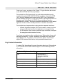
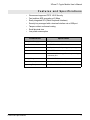
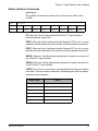
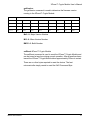
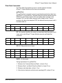
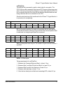
XPress™ Crypto Module
User’s Manual
FIPS 140-2 Security Module
90033945_D
June 7, 2011
©2011 Digi International Inc.
Printed in the United States of America. All rights reserved.
Digi, Digi International, the Digi logo, a Digi International Company, are trademarks or
registered trademarks of Digi International, Inc. in the United States and other countries
worldwide. All other trademarks are the property of their respective owners.
Information in this document is subject to change without notice and does not represent a
commitment on the part of Digi International.
Digi provides this document “as is,” without warranty of any kind, either expressed or implied,
including, but not limited to, the implied warranties of, fitness or merchantability for a particular
purpose. Digi may make improvements and/or changes in this manual or in the product(s) and/
or the program(s) described in this manual at any time.
This product could include technical inaccuracies or typographical errors. Changes are made
periodically to the information herein; these changes may be incorporated in new editions of the
publication.
XPress™ Crypto Module User’s Manual
About This Guide 4
Digi Contact Information 4
Features and Specifications 5
Secure Setup and Initialization 6
Module Physical Interface 11
Module SPI Interface 12
Status and Reset Commands 14
getStatus: 14
getVersion: 15
setReset:XPress™ Crypto Module 15
Plain Data Commands 16
getPlainText: 16
setPlainText: 17
Cipher Data Commands 18
getCipherText: 18
Contents
3
XPress™ Crypto Module User’s Manual
About This Guide
Thank you for your purchase of the XPress™ Crypto Module, also known
as the AW140 FIPS 140-2 Security Module.
This module from Digi International is a multi-chip embedded security
module that performs AES 128/192/256 bit encryption. It meets the FIPS
140-2 Security Standard and is approved by CMVP (the Cryptographic
Module Validation Program), a joint effort of NIST (The National Institute of
Standards and Technology) and CESC (Communications Security
Establishment Canada). This approval indicates acceptance by the Federal
Agencies of both countries for the protection of sensitive information.
The module has a tamper-evident coating and two separate interfaces:
• A Serial Peripheral Interface (SPI) that is used to connect to a host
microcontroller and transfers encrypted an non-encrypted data.
• A USB interface that is used to establish login credentials, configure
the encryption method and set the key.
If you have any questions when configuring your Digi product, please visit
www.digi.com/support. If further assistance is needed, send an e-mail to
[email protected]. To speak to a live technician, please call technical
support at the number listed below, during normal business hours.
Digi Contact Information
To contact Digi International for more information about your Digi products,
or for customer service and technical support, use the following contact
information:
To Contact Digi International by:
About this Guide
Use:
Mail
Digi International
11001 Bren Road East
Minnetonka, MN 55343
U.S.A.
World Wide Web:
http://www.digi.com/support/
email
http://www.digi.com/support/eservice
Telephone (U.S.)
(952) 912-3444 or (877) 912-3444
Telephone (other locations)
+1 (952) 912-3444 or (877) 912-3444
4
XPress™ Crypto Module User’s Manual
Features and Specifications
•
•
•
Government approved FIPS 140-2 Security
Fast realtime AES encryption at 5 Mbps
Easily integrated SPI (Serial Peripheral Interface)
•
•
•
•
Security key managed with a terminal interface via a USB port
Tamper-evident conformal coating
Small physical size
Low power consumption
Characteristic
Specification
Encryption Throughput
5 Mbps
Certifications
NIST FIPS 140-2, NIST FIPS 197
SPI Data Interface
2 x 5 pin header, 0.1” spacing plus 3 pin support
Command Interface
Mini USB Socket
Size
30mm wide, 50mm long, 15mm deep including
connector pins
Voltage Range
3.1 to 3.6 VDC
Power Consumption
45 ma at 3.3 VDC (150 mW)
Operating Temperature Range
-70° C to +80° C
Features and Specifications
5
XPress™ Crypto Module User’s Manual
Secure Setup and Initialization
If you have a Digi radio with FIPS 140-2 Security, this supplement to the
User Manual provides instructions for setting up the encryption. Please
disregard the AES Encryption instructions in the regular manual: this
supersedes them. A feature of the level of security provided is that there is
no way to change the encryption method or key through the radio’s
interface. A separate port must be used.
The XPress™ Crypto Module is programmed and queried through a
terminal interface. To use the terminal interface, you must install the
following two pieces of software:
1. A driver that provides a virtual COM port through the USB connection.
This driver can be downloaded from the Future Technology Devices
International website, http://www.ftdichip.com. Follow their menu to the
webpage for VCP drivers and choose the one that matches your operating system. Installation guides are also available in the documents
section of the website.
2. A terminal emulator that will provide the user interface to the XPress™
Crypto Module. Options include Hyper-Terminal (available automatically
in Windows XP and earlier operating systems) or Digi's XCTU available
at www.digi.com/xctu. Customers using non-Windows OS can use tools
such as minicom for Linux Ubuntu or ZTerm for Mac.
There are two roles defined for those having access to the programming
interface, Crypto Officer and User. Each has a different password. Only the
Crypto Officer is allowed to set the encryption method and encryption key.
The user may examine self test results and firmware version only.
Secure Setup & Installation
6
XPress™ Crypto Module User’s Manual
Step by step programming procedure:
1. Connect your hardware.
If your module is connected to a development board or is a standalone
module, make sure the main power for the radio is off, and connect the
XPress™ Crypto Module's USB port to your computer using a USB mini B
cable.
If you have purchased an XPress™ Crypto Module as part of an XPress™
Ethernet Bridge, remove the cover of the XPress™ Ethernet Bridge using a
Phillips screwdriver. The USB cable coiled inside the XPress™ Ethernet
Bridge should be plugged into your PC's USB port. Power your XPress™
Ethernet Bridge using Power over Ethernet. Then press the reset button
located in the middle of the XPress™ Ethernet Bridge PCB as shown in the
image below.
2. Open your terminal emulator program and set the COM port settings as
follows:
Data bits:
8
Baud rate:
115200
Parity:
none
Stop bits:
1
Flow control:
none
3. Press any key to activate the XPress™ Crypto Module. If the module
has never been programmed, setup prompts will occur as shown in the
example screen shot below. If you see only a login prompt, then the
module has previously been initialized. If you know the password, enter
it. If not, type “init” to erase all keys and passwords and return the module to its uninitalized state.
Secure Setup & Installation
7
XPress™ Crypto Module User’s Manual
4. Initial Setup.
Passwords must be between 8 and 32 characters. Passwords are casesensitive and any ASCII characters may be used.
You may select a 128, 192, or 256 bit encryption key. The encryption
key must be entered as a 32, 48, or 64 digit hexadecimal number (0-9,
a-f), corresponding to the length of the encryption key selected. If you
enter less than the full number of digits, the XPress™ Crypto Module
will pad your key with zeros.
5. After completing the initial setup, disconnect the USB cable. If you are
using the XPress™ Crypto Module as part of an XPress™ Ethernet
Bridge, replace the ESD cap on the USB connector to ensure the USB
connector will not cause damage inside the unit, recoil the USB cable
inside the XPress™ Ethernet Bridge using the reusable cable tie, and
replace the enclosure cover. Next, power up the Digi radio to resume
normal cryptographic operation.
Secure Setup & Installation
8
XPress™ Crypto Module User’s Manual
6. It may become necessary to change the programming or test the module at some later time. Connect your hardware as shown in step 1 then
set up the COM port parameters and terminal emulator program as
described in step 2. A screen similar to the one below will display:
Self Test Results displays the results of the power up self test. At power
up, the XPress™ Crypto Module runs a known answer test for all
encryption/decryption
algorithms.
Firmware Version displays the revision number of the firmware
running in the XPress™ Crypto Module.
Change Algorithm and Change Key can only be used by the Crypto
Officer Role. If the User Role attempts to run these commands, an error
occurs as shown in the above screen shot.
Change Password allows a new choice for the Crypto Officer or User
password, depending on which Role is logged in.
Display Command List will display the list of available commands.
Secure Setup & Installation
9
XPress™ Crypto Module User’s Manual
Logout will log you out of the XPress™ Crypto Module.
Note:
If an incorrect password is entered at the login prompt, two more tries are
allowed and then the XPress™ Crypto Module enters a lockout state for 5
minutes.
7. After completing the setup or testing, log out and disconnect the USB
cable. If you are using the XPress™ Crypto Module as part of an
XPress™ Ethernet Bridge, replace the ESD cap on the USB connector
to ensure the USB connector will not cause damage inside the unit,
recoil the USB cable inside the XPress™ Ethernet Bridge using the
reusable cable tie, and replace the enclosure cover. Next, power up the
Digi radio to resume normal cryptographic operation.
Secure Setup & Installation
10
XPress™ Crypto Module User’s Manual
Module Physical Interface
Signal definitions for the XPress™ Crypto Module SPI interface:
Pin Number
Module Physical Interface
Name
Description
1
Vcc
3.3 VDC power for module
2
SCK
Serial clock
3
MOSI
Serial data input to module
4
MISO
Serial data output from module
5
GND
Module ground
6
#RESET
Active low reset
7
FIFO Full Flag
0 = FIFO empty
1 = FIFO full, don’t send any more data
8
Data Ready
0 = no data
1 = data packet available
9
Error
1 = Error occurred
To clear flag, de-assert Chip Select
10
#CS
Active Low Chip Select
11
XPress™ Crypto Module User’s Manual
Module SPI Interface
Serial Peripheral Interface (SPI) is a full duplex synchronous serial
interface that allows data to be shifted in and out of the XPress™ Crypto
Module 8 bits at a time (most significant bit first).
The SPI requires 4 pins to be physically connected:
•
•
•
•
SCK - Serial Bit Shift Clock (provided by master SPI)
MISO - Master In Slave Out
MOSI - Master Out Slave In
CS - Active Low Chip Select
The SPI on the XPress™ Crypto Module is a slave SPI and uses mode (1,
1) for clock phase and polarity. This means that the SCK line idles high and
data is setup on the falling edge of the clock and latched on the rising edge.
The maximum clock rate for the SPI is 7MHz and the minimum clock rate
its 530kHz.
The SPI operates in slave mode, meaning SCK is supplied by an external
source. This interface is used to transfer data to and from the module and
to read status information.
The first byte on the MOSI line after the #CS line goes low is the Command
Byte. This byte tells the XPress™ Crypto Module what command is to be
executed.
Module SPI Interface
12
XPress™ Crypto Module User’s Manual
Command Byte:
b7
b6
b5
b4
b3
b2
b1
b0
get/set
-
-
-
-
-
CMD1
CMD0
When the get/set bit is set, information will be sent to the XPress™ Crypto
Module on MOSI and MISO will be high impedance. When clear, a get
transaction will take place and information will be sent from the XPress™
Crypto Module on MISO.
After the command byte is issued the master microcontroller must delay to
allow the XPress™ Crypto Module enough time to prepare for the
transaction. See the timing diagrams with each command for the delay
times to use.
When a data transaction is complete and the #CS line is high, the master
microcontroller must delay to allow the XPress™ Crypto Module to finish
processing the transaction.
CMD1 and CMD0 are used to tell the XPress™ Crypto Module what
command is to be executed according to this table:
Command Byte - HEX
Module SPI Interface
Command
0x00
getSTATUS
0x01
getPlainText
0x02
getCipherText
0x03
getVersion
0x80
INVALID
0x81
setPlainText
0x82
setCipherText
0x83
setReset
13
XPress™ Crypto Module User’s Manual
Status and Reset Commands
getStatus:
The getStatus command is used to find out the current status of the
module.
0x00
Byte1
getStatus
b7
b6
b5
b4
b3
b2
b1
b0
ST
DFIFO
EFIFO
DDATA
EDATA
CODE2
CODE1
CODE0
ST: When set, this bit indicates that the XPress™ Crypto Module is
performing power up self test.
DFIFO: When set, this bit indicates that the Decipher FIFO is full; no more
ciphertext can be transferred to the module until some plaintext is read out.
EFIFO: When set, this bit indicates that the Encipher FIFO is full; no more
plaintext can be transferred to the module until some ciphertext is read out.
DDATA: When set, this bit indicates that plaintext is ready to be read out of
the XPress™ Crypto Module.
EDATA: When set, this bit indicates that ciphertext is ready to be read out
of the XPress™ Crypto Module.
CODE2...0: If an error occurs (error line asserted) there will be a condition
code here. The error must be cleared by de-asserting the #CS line before
operation can be resumed.
Error Code
Module SPI Interface
Error
0x00
Null/No code
0x01
Self test in progress
0x02
Last command not understood
0x03
Data size invalid
0x04
No code
0x05
Self test failed
14
XPress™ Crypto Module User’s Manual
getVersion:
The getVersion command is used to determine the firmware version
running in the XPress™ Crypto Module.
0x03
getVersion
b7
b6
b5
b4
b3
b2
b1
b0
Byte1
Ma3
Ma2
Ma1
Ma0
Mi3
Mi2
Mi1
Mi0
Byte2
BN15
BN14
BN13
BN12
BN11
BN10
BN9
BN8
Byte3
BN7
BN6
BN5
BN4
BN3
BN2
BN1
BN0
Ma3...0: Major Version Number
Mi3...0: Minor Version Number
BM15...0: Build Number
setReset:XPress™ Crypto Module
The setReset command is used to reset the XPress™ Crypto Module and
can be issued at any time during normal operation. After a reset has been
issued the XPress™ Crypto Module takes approximately 300ms to restart.
There are no other bytes required to reset the device. The host
microcontroller simply needs to send the 0x83 Command Byte.
Module SPI Interface
15
XPress™ Crypto Module User’s Manual
Plain Data Commands
The Plain Data Commands are used to transfer plaintext between
XPress™ Crypto Module and the host microcontroller.
getPlainText:
The getPlainText command is used to read deciphered plaintext data from
the XPress™ Crypto Module. The Data Ready line will be asserted and the
EDATA bit of the status register will be set when data is present in the
decipher FIFO and will remain asserted until all data is read. There is
protection for data in the decipher FIFO; the data will remain present until it
has been read out.
0x01
Byte1
getPlainText
b7
b6
b5
b4
b3
b2
b1
b0
ID7
ID6
ID5
ID4
ID3
ID2
ID1
ID0
ID7...0: A packet identifier, the same one associated with the packet when
it was sent to the XPress™ Crypto Module using the setCipherText
command.
b7
b6
b5
b4
b3
b2
b1
b0
Byte2
-
-
-
-
-
S10
S9
S8
Byte3
S7
S6
S5
S4
S3
S2
S1
S0
S10...0: Data packet size in bytes.
b7
b6
b5
b4
b3
b2
b1
b0
Byte4
DATA7
DATA6
DATA5
DATA4
DATA3
DATA2
DATA1
DATA0
...
DATA7
DATA6
DATA5
DATA4
DATA3
DATA2
DATA1
DATA0
ByteN
DATA7
DATA6
DATA5
DATA4
DATA3
DATA2
DATA1
DATA0
DATA7...0: Data bytes.
Timing requirements for getPlainText:
1. Between the Command Byte and Byte1, at least 4.0 µs.
2. Between Byte1 and Byte2, Byte2 and Byte3, at least 0.5 µs.
3. Between each data byte, at least 1.0 µs.
4. After the last data byte and before de-asserting #CS, at least 2.0 µs.
Module SPI Interface
16
XPress™ Crypto Module User’s Manual
setPlainText:
The setPlainText command is used to submit data for encryption. The
FIFO Full line will be asserted if the transmit FIFO cannot accept any more
data. If the host microcontroller attempts to submit data while the FIFO Full
line is asserted then the Error line will also become asserted and the data
being submitted will not be entered into the FIFO.
Once the data has been fully transferred to the XPress™ Crypto Module, it
is queued up for enciphering.
0x81
Byte1
setPlainText
b7
b6
b5
b4
b3
b2
b1
b0
ID7
ID6
ID5
ID4
ID3
ID2
ID1
ID0
ID7...0: A packet identifier, this value is associated with the data packet
and will be sent back to the host microcontroller when the enciphered data
is read back out using the getCipherText command.
b7
b6
b5
b4
b3
b2
b1
b0
Byte2
-
-
-
-
-
S10
S9
S8
Byte3
S7
S6
S5
S4
S3
S2
S1
S0
S10...0: Data packet size in bytes. The number of bytes must be between 1
and 2047.
b7
b6
b5
b4
b3
b2
b1
b0
Byte4
DATA7
DATA6
DATA5
DATA4
DATA3
DATA2
DATA1
DATA0
...
DATA7
DATA6
DATA5
DATA4
DATA3
DATA2
DATA1
DATA0
ByteN
DATA7
DATA6
DATA5
DATA4
DATA3
DATA2
DATA1
DATA0
DATA7...0: Data bytes.
Timing requirements for setPlainText:
1. Between the Command Byte and Byte1, at least 1.8 µs.
2. Between Byte1 and Byte2, Byte2 and Byte3, at least 0.5 µs.
3. Between Byte3 and the first data byte, at least 2.0 µs.
4. Between each data byte, at least 1.1 µs.
5. After the last data byte and before de-asserting #CS, at least 4.5 µs.
Module SPI Interface
17
XPress™ Crypto Module User’s Manual
Cipher Data Commands
The Cipher Data commands are used to transfer ciphertext between
XPress™ Crypto Module and the host microcontroller. They behave in a
very similar manner to the Plain Data Commands just described.
getCipherText:
The getCipherText command is used to read ciphered data from the
XPress™ Crypto Module. The Data Ready line will be asserted and the
DDATA bit of the status register will be set when data is present in the
encipher FIFO and will remain asserted until all data is read. There is
protection for data in the encipher FIFO; the data will remain present until it
has been read out.
0x02
Byte1
getCipherText
b7
b6
b5
b4
b3
b2
b1
b0
ID7
ID6
ID5
ID4
ID3
ID2
ID1
ID0
ID7...0: A packet identifier, the same one associated with the packet when
it was sent to the XPress™ Crypto Module using the setPlainText
command.
b7
b6
b5
b4
b3
b2
b1
b0
Byte2
-
-
-
-
-
S10
S9
S8
Byte3
S7
S6
S5
S4
S3
S2
S1
S0
S10...0: Data packet size in bytes.
b7
b6
b5
b4
b3
b2
b1
b0
Byte4
DATA7
DATA6
DATA5
DATA4
DATA3
DATA2
DATA1
DATA0
...
DATA7
DATA6
DATA5
DATA4
DATA3
DATA2
DATA1
DATA0
ByteN
DATA7
DATA6
DATA5
DATA4
DATA3
DATA2
DATA1
DATA0
DATA7...0: Data bytes.
Timing requirements for getCipherText:
1.
2.
3.
4.
Module SPI Interface
Between the Command Byte and Byte1, at least 4.0 µs.
Between Byte1 and Byte2, Byte2 and Byte3, at least 0.5 µs.
Between each data byte, at least 1.0 µs.
After the last data byte and before de-asserting #CS, at least 2.0 µs.
18