1
INSTRUCTION MANUAL
Leak Logger for Measuring & Recording leakage current
KEW LEAK LOGGER
MODEL 5000/5001
KYORITSU ELECTRICAL INSTRUMENTS
WORKS,LTD.
Contents
1. Safety warnings ............................................................................... 1
2. Features
............................................................................... 3
3. Instrument layout............................................................................... 4
3-1) Panel
............................................................................... 4
3-2) Menu configuration ................................................................... 5
3-3) LCD .......................................................................................... 7
3-4) Displayed message .................................................................. 8
4. Recording procedures ...................................................................... 9
Step1: Preparation ......................................................................... 10
Step2: Confirmation and change of set value ................................ 11
Step3: Preparation before a recording .......................................... 12
Step4: Start of recording ................................................................ 14
Step5: Stop of recording ................................................................ 15
5. Recording modes and conditions ................................................... 16
Continuous recording mode .......................................................... 16
Event recording mode ................................................................... 19
Max value recording mode ............................................................. 21
Capture recording mode ................................................................. 23
6. Recording modes ........................................................................ 25
7. Other settings (Setting2) ................................................................. 30
8. Data transfer to PC ........................................................................ 35
9. Battery replacement ........................................................................ 37
10.Specification .................................................................................. 38
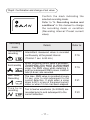
1. Safety Warnings
This instrument has been designed, manufactured and tested according
to IEC 61010: Safety requirements for Electronic Measuring apparatus,
and delivered in the best condition after passed the inspection. This
instruction manual contains warnings and safety rules which must be
observed by the user to ensure safe operation of the instrument and
retain it in safe condition. Therefore, read through these operating
instructions before using the instrument.
WARNING
¡ Read through and understand the instructions contained in this
manual before starting to use the instrument.
¡ Save and keep the manual at hand to enable quick reference
whenever necessary.
¡ Be sure to use the instrument only in its intended applications.
¡ Be sure to understand and follow all safety instructions contained
in the manual.
Be sure to observe the above instructions. Failure to follow the above
instructions may cause injury, instrument damage and/or damage to
equipment under test.
The symbol
indicated on the instrument means that the user must
refer to related parts in the manual for safe operation of the instrument.
Be sure to carefully read the instructions following each
symbol in
the manual.
DANGER is reserved for conditions and actions that are likely to
cause serious or fatal injury.
WARNING is reserved for conditions and actions that can cause
serious or fatal injury.
CAUTION is reserved for conditions and actions that can cause a
minor injury or instrument damage.
―1―
DANGER
¡ Never make measurement on the circuit in which voltage over
AC300V exists.
¡ Do not attempt to make measurement in the presence of flammable
gasses.
Otherwise, the use of the instrument may cause sparking, which
can lead to an explosion.
¡ Transformer jaw tips are designed not to short the circuit under test.
If equipment under test has exposed conductive parts, however,
extra precaution should be taken to minimize the possibility of
shorting.
¡ Never attempt to use the instrument if its surface or your hand is
wet.
¡ Do not exceed the maximum allowable input of any measuring
range.
¡ Never open the Battery cover during a measurement.
¡ Verify proper operation on a known source before use or taking
action as a result of the indication of the device.
WARNING
¡ Never attempt to make measurement if any abnormal conditions,
such as broken case and exposed metal parts are found on the
instrument.
¡ Do not install substitute parts or make any modification to the
instrument.
For repair or re-calibration, return the instrument to your local KEW
distributor from where it was purchased.
¡ Do not try to replace the batteries if the surface of the instrument is
wet.
¡ Make sure to remove the input clamps, and power off the
instrument when opening the Battery cover for battery replacement.
CAUTION
¡ Do not expose the instrument to the direct sun, high temperature
and humidity or dewfall.
¡ Be sure to power off the instrument after use. When the instrument
will not be in use for a long period, place it in storage after removing
the batteries.
¡ Use a cloth dipped in water or neutral detergent for cleaning the
instrument.
Do not use abrasives or solvents.
―2―
2. Features
¡ This instrument is a leak logger for measuring and recording
leakage current.
¡ Capable of recording leakage current from 1 to 3ch with leakage
clamp sensor. (Leak clamp sensors: M-8141/8142/8143 are
available.)
¡ Can measure and record max. AC1000mA(50/60Hz) with RMS.
¡ LED current indicator flashes when the preset current value is
exceeded. (Event/ Max. value/ Capture recording mode)
¡ Can store 60,000 data when using 1ch, and when using all 3ch,
can store 20,000 data at each channel. (Continuous recording
mode)
¡ Data will not be lost at battery replacement or at lower battery
voltage as it is stored in nonvolatile memory.
¡ Can perform recording for long time with Power-save function.
¡ Can transfer the recorded data to PC via USB cable.
¡ Protected throughout by double (reinforced) insulation "F".
¡ This instrument provides 4 recording modes. Can be used for
any kinds of insulation controls since the user can select any
desirable recording mode as usage. Read through the
instruction manual and understand the features of each
recording mode to select the appropriate recording mode.
―3―
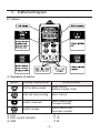
3.Instrument layout
3-1) Panel
¡ Operation of button
Button
At recording / measurement mode:
At menu mode:
Shift to Menu mode
Select Menu,
Setting change, Enter
Start and stop recording
Back, Cancel
Switch channels
Switch Menu item,
Increase number
Switch ranges
Switch Menu item,
Decrease number
¡ LCD
¡ LED current indicator
¡ USB
・・・ P. 7
・・・ P.18
・・・ P.35
―4―
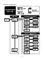
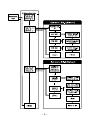
3-2) Menu configuration
―5―
―6―
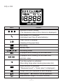
3-1) LCD
100mA
1000mA
Mark
Details
Selected channel number
(The measured value at this channel is displayed.)
Auto-power-off is disabled.
(Instrument won't be off automatically.)
Timer function is activated.
(Stand-by till the preset time.)
Recording
Battery mark
Recording mode
Displayed when viewing the recorded data.
Displayed when viewing the recorded max.
and min. value.
One-time system is activated.
(Recording stops when memory becomes full.)
Scale function is activated.
("Measured result" x "Scale value" is displayed.)
Range hold (Not displayed at auto-ranging.)
Menu guide (▲/▼button can be operated.)
Measurement range (100.0mA/1000mA)
―7―
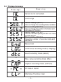
3-4)Displayed message
Meaning
Message
Sensor is not connected.
Over-range
Menu: Setting1(SET.1)
View or change the recording mode/ condition.
Menu: Setting2(SET.2)
View or change the Location information and
auto-power-off function.
Menu: Status 1(STS.1)
View the recorded quantity and the max. value
at each channel.
Menu: Status 2(STS.2)
View the number of recorded data and
RECALL.
Menu: End
Continuous recording mode (LOGging)
Event recording mode (detect)
Max. value recording mode (Max)
Capture recording mode (CAPture)
PC data in transit
Warning of memory clear
―8―
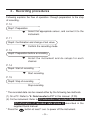
4.Recording procedures
Following explains the flow of operation: through preparation to the stop
of recording.
P. 10
Step1: Preparation
▼
Select the appropriate sensor, and connect it to the
instrument.
P. 11
Step2: Confirmation and change of set value
▼
Confirm the recording mode.
P. 12
Step3: Preparation before a recording
▼
Install the instrument and do setups for each
channel.
P. 14
Step4: Start of recording
▼
Start recording.
P. 15
Step5: Stop of recording
Stop recording.
* The recorded data can be viewed either by the following two methods.
(1) On a PC: Refer to "8. Data transfer to PC" in this manual. (P.35)
(2) On the instrument: Refer to (2)Confirmation of recorded data (status 1)
and (3)Confirmation of recorded data (status 2) described in the
supplied Quick manual.
* Press the
button at least 1 sec. to power off the instrument.
―9―
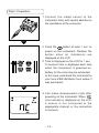
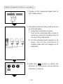
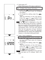
Step1: Preparation
1. Connect the clamp sensor to the
instrument firmly with careful attention to
the orientation of the connector.
2. Press the
button at least 1 sec. to
power on the instrument. Release the
button when all indications are
displayed on the LCD.
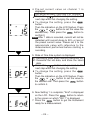
3. Time is displayed on the LCD for 1 sec.
If incorrect time is displayed each time
when the instrument is powered on,
battery for the clock may be exhausted.
In this case, send back the instrument to
your local KEW distributor from where it
was purchased.
4. Can make measurement right after
powering on the instrument. When
(non-connect) is displayed on the LCD,
a sensor is not connected to the
appropriate channel; or the connection
is incorrect.
― 10 ―
Step2: Confirmation and change of set value
Confirm the mark indicating the
selected recording mode.
Refer to "5. Recording modes and
conditions" in this manual to change
the recording mode or condition
(Recording interval/ Preset current
value).
Recording
mode
Continuous
recording
Event recording
Max. value
Recording
Capture
recording
Details
Refer to:
Intermittent measured value is recorded
continuously at the preset interval.
(15-kind: 1 sec. to 60 min.)
P.16
When the preset current value is exceeded ,
(hereinafter, this event is referred as
current detection) three previous RMS
value, the RMS value when detecting it,
and four subsequent RMS values, 8 data in
total (0.8 sec.) are recorded.
P.19
The max. RMS value is recorded at every
10 sec. prior to and subsequent to the
current detection. It ends when a value
drops to 50% or less of the preset current
value; or when 10 min. has been elapsed.
P.21
Ten to twelve waveforms (for 200mS) are
recorded prior to and subsequent to the
current detection.
P.23
― 11 ―
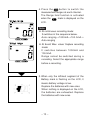
Step3: Preparation before a recording
1. Clamp on the measured object and fix
the Clamp sensor.
㩷
㩷
㩷
2. Instrument shall be firmly fixed so as not
to come off easily.
1)Hang the instrument on hook:
Can fix the instrument with a hook or
screw by using the hooking hole on
the top of the instrument.
2)Fix the instrument with magnet on its
back. Can fix the instrument to
metallic plate with the magnet on its
backside.
㩷
3. Press the
button to switch the
display of measured value among
Channel (1) and (3).
㩷
㩷
― 12 ―
4. Press the
button to switch the
measurement ranges at each channel.
The Range hold function is activated
when the
mark is displayed on the
LCD.
㩷
㩷
㩷
Note
¡ At continuous recording mode:
It switches in the sequence below.
Auto-ranging→1000mA→100.0mA→
Auto-ranging
¡ At Event/ Max. value/ Capture recording
mode:
It switches between 1000mA and
100.0mA.
Range cannot be switched during a
recording. Select the appropriate range
before a recording.
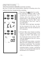
5. When only the leftmost segment of the
Battery mark is flashing on the LCD, it
means battery voltage is low.
Replace the batteries with new ones.
When nothing is displayed on the LCD,
the batteries are exhausted. Replace
the batteries with new ones.
― 13 ―
Step4: Start of recording
Follow the procedures stated below and start recording.
Be sure to check each setting before starting a recording since the
settings cannot be changed during a recording.
㩷
㩷
㩷
㩷
1. Press down the
button for a while.
¡ At continuous recording mode or after
changing the recording mode; "CLr"
flashes while the button is being
pressed down. A few seconds later, the
measured value and the "REC" mark
are displayed on the LCD. Then a
recording starts.
(The data, which had been recorded,
will be cleared at this time. So the
important data must be transferred to
PC in advance.)
¡ At Event/ Max value/ Capture recording
mode or the recording mode is not
changed, the "REC" mark flashes and
the measured value and the "REC"
mark are displayed on the LCD. Then a
recording starts.
(At these recording modes, recorded
data will not be cleared when continuous
recording is performed. The recorded
data will be deleted when changing a
recording mode or sensor connecting
channel. So the important data must be
transferred to PC in advance.)
― 14 ―
Following operations are available during a recording.
* Display the measured value at each channel
button
* Recording state: Display the max. recorded value
→Refer to (2) Confirmation of recorded data (status 1) described
in the supplied Quick manual.
* Recording state: Display RECALL
→Refer to (3) Confirmation of recorded data (status 2) described
in the supplied Quick manual.
* Confirm the setting value at Setting1 "SEt.1" and Setting2 "SEt.2".
Following operations are NOT available during a recording.
* Power off the instrument.
* Switch measurement ranges.
* Change the setting value at Setting1 "SEt.1" and Setting2 "SEt.2".
* Communication with PC
Stop the recording once to do above operations.
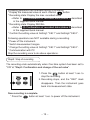
Step5: Stop of recording
The recording ends automatically when One-time system has been set to
"ON" at "Step2: Confirmation and change of the set value".
1. Press the
button at least 1 sec. to
stop the recording.
2. Recording stops, and the "REC" mark
disappears. Then the instrument goes
back into measurement state.
Now recording is complete.
* Press the
button at least 1 sec. to power off the instrument.
― 15 ―
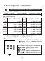
5. Recording modes and conditions
Continuous recording mode: Recording interval of 1min.
Max. number of recorded data
Using all 3 channels
Using 2 channels
20,000 data
40,000 data
Max. recording duration
Recording
interval
1sec.
2sec.
5sec.
10sec.
15sec.
20sec.
30sec.
Using only 1 channel
60,000 data
Recording
Using all 3 channels
interval
5:33:20 1min.
13 days/ 21:20:00
11:06:40 2min.
27 days/ 18:40:00
1 day/ 3:46:40 5min.
69 days/ 10:40:00
2 days/ 7:33:20 10min.
138 days/ 21:20:00
3 days/ 11:20:00 15min.
208 days/ 8:00:00
4 days/ 15:06:40 20min.
277 days/ 18:40:00
6 days/ 22:40:00 30min.
416 days/ 16:00:00
60min.
833 days/ 8:00:00
Note) * Max. recoding duration is limited by the battery life.
* Max. recording duration is lengthened by 1.5 times when using 2
channels, and tripled when using 1 channel only.
Setting procedure
1. Power on the instrument, and press the
button. Then the instrument goes into
Menu mode.
Using all 3 channels
Each button acts as follows at Menu mode.
→
:Select, Change, Enter
→
:Return, Cancel
→
:Switch, Increase set value
→
:Switch, Decrease set value
㩷
― 16 ―
㩷
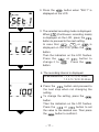
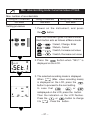
2. Press the
button when "SEt.1" is
displayed on the LCD.
㩷
㩷
㩷
㩷
3. The selected recording mode is displayed.
When
(Continuous recording mode)
is displayed on the LCD, press the
button to proceed to the next setting.
In case that
,
or
is
displayed on the LCD, press the
button.
Then the indication on the LCD flashes.
Press the
or
button to
change it to
. Press the
button.
4. The recording interval is displayed.
Can be selected from; 1, 2, 5, 10, 15, 20, 30 sec.,
1, 2, 5, 10, 15, 20, 30, 60 min
㩷
㩷
button and proceed to
¡ Press the
the next step when not changing the
setting.
¡ To change the setting, press the
button.
Then the indication on the LCD flashes.
Press the
or
button to set
the value to the desired one. Then press
the
button to confirm it.
― 17 ―
㩷
㩷
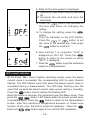
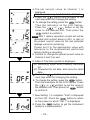
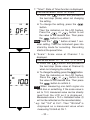
5. State of One-time system is displayed.
on: Recording stops when memory becomes
full.
off: Overwrite the old data, and store the
latest data.
button and proceed to
¡ Press the
the next step when not changing the
setting.
¡ To change the setting, press the
button.
Then the indication on the LCD flashes.
Press the
or
button to set
the value to the desired one. Then press
the
button to confirm it.
㩷
㩷
6. Now Setting 1 is complete; "End" is
displayed on the LCD. Press the
button to return to the screen on which
"SEt.1" is displayed.
7. Press the
button to get the instrument
ready for a measurement.
LED current indicator
* At the Event/ Max. value/ Capture recording modes, when the preset
current value is exceeded, the corresponding LED for each channel
flashes. The LED flashes each time when the preset current value is
exceeded during a measurement. The LED keep flashing once the
event that exceeds the preset current value occurs during a recording.
Press the
button once to restore the flashing LED.
When the button is pressed, the instrument goes into Menu mode. Then
press the
button. LED flashes when the preset current value
is exceeded again. Press the
button to return to the measurement
screen; after the indications disappeared because of Power-save
function. In this case, the LED is turned off temporary . Press the
button and
button again to turn off the LED completely.
― 18 ―
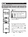
Event recording mode: Current set value of 15mA
Max. number of recorded data
Using all 3 channels
Using 2 channels
1,600 data
2,400 data
Using only 1 channel
4,800 data
Setting procedure
1. Power on the instrument, and press the
button.
Then the instrument goes into Menu mode.
Each button acts as follows at Menu mode.
→
:Select, Change, Enter
→
:Return, Cancel
→
:Switch, Increase set value
→
:Switch, Decrease set value
㩷
2. Press the
button when "SEt.1" is
displayed on the LCD.
㩷
㩷
㩷
3. The selected recording mode is displayed.
When
(Event recording mode) is
displayed on the LCD, press the
button to proceed to the next setting.
In case that
,
or
isdisplayed on the LCD, press the
button.
Then the indication on the LCD flashes.
Press the
or
button to change
it to
. Press the
button.
㩷
― 19 ―
㩷
㩷
㩷
㩷
㩷
㩷
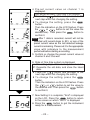
4. Pre-set current value at channel 1 is
displayed.
Can be set at every 1mA from 0 to 1000mA
button and proceed to the
¡ Press the
next step when not changing the setting.
button.
¡ To change the setting, press the
Then the indication on the LCD flashes.
Press the
or
button to set the
value to the desired one. Then press the
button to confirm it.
Note After 1 data is recorded, current will not be
detected until current drops to 50% or less of
the preset current value as the last detected
leakage current is remaining.
Please set it to the appropriate value with
reference to the measurement performed
before starting a recording.
5. Confirm or change the preset current value on
channel 2 and 3 as well.
6. State of One-time system is displayed.
on: Recording stops when memory becomes
full.
off: Overwrite the old data, and store the latest
data.
button and proceed to the
¡ Press the
next step when not changing the setting.
button.
¡ To change the setting, press the
Then the indication on the LCD flashes. Press
the
or
button to set the value to
the desired one. Then press the
button
to confirm it.
7. Now Setting 1 is complete; "End" is displayed
on the LCD. Press the
button to return
to the screen on which "SEt.1" is displayed.
8. Press the
button to get the instrument
ready for a measurement.
㩷
― 20 ―
Max. value recording mode: Current set value of 15mA
Max. number of recorded data
Using all 3 channels
Using 2 channels
330 data
495 data
Using only 1 channel
990 data
Setting procedure
1. Power on the instrument, and press
the
button.
Then the instrument goes into Menu mode.
Each button acts as follows at Menu mode.
→
:Select, Change, Enter
→
:Return, Cancel
㩷
→
:Switch, Increase set value
→
:Switch, Decrease set value
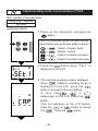
2. Press the
button when "SEt.1" is
displayed on the LCD.
㩷
㩷
㩷
3. The selected recording mode is displayed.
When
(Max. value recording mode)
is displayed on the LCD, press the
button to proceed to the next setting.
In case that
,
or
isdisplayed on the LCD, press the button.
Then the indication on the LCD flashes.
Press the
or
button to change
it to
. Press the button.
㩷
― 21 ―
㩷
㩷
㩷
㩷
㩷
4. Pre-set current value on channel 1 is
displayed.
Can be set at every 1mA from 0 to1000mA.
button and proceed to the
¡ Press the
next step when not changing the setting.
¡ To change the setting, press the
button.
Then the indication on the LCD flashes. Press
the
or
button to set the value the
desired one). Then press the
button to
confirm it.
Note After 1 data is recorded, current will not be
detected until current drops to 50% or less of the
preset current value as the last detected leakage
current is remaining. Please set it to the appropriate
value with reference to the measurement
performed before starting a recording.
5. Confirm or change the preset current value at
channel 2 and 3 as well.
6. State of One-time system is displayed.
on: Recording stops when memory becomes full
off: Overwrite the old data, and store the latest
data.
button and proceed to the
¡ Press the
next step when not changing the setting.
¡ To change the setting, press the
button.
Then the indication on the LCD flashes. Press
the
or
button to set the value to
the desired one. Then press the
button
to confirm it.
㩷
㩷
7. Now Setting 2 is complete; "End" is displayed
on the LCD. Press the
button to return
to the screen on which "SEt.2" is displayed.
8. Press the
button to get the instrument
ready for a measurement.
― 22 ―
Capture recording mode: Current set value of 15mA
Max. number of recorded data
Using only 1 channel
345 data
Setting procedure
1. Power on the instrument, and press the
button.
Then the instrument goes into Menu mode.
Each button acts as follows at Menu mode.
→
:Select, Change, Enter
→
:Return, Cancel
㩷
→
:Switch, Increase set value
→
:Switch, Decrease set value
2. Press the
button when "SEt.1" is
displayed on the LCD.
㩷
㩷
㩷
3. The selected recording mode is displayed.
When
(Capture recording mode) is
displayed on the LCD, press the
button to proceed to the next setting.
In case that
,
or
isdisplayed on the LCD, press the
button.
Then the indication on the LCD flashes.
Press the
or
button to change
it to
. Press the
button.
㩷
― 23 ―
㩷
㩷
㩷
㩷
4. Pre-set current value on channel 1 is
displayed.
Can be set at every 1mA from 0 to 1000mA.
button and proceed to the
¡ Press the
next step when not changing the setting.
¡ To change the setting, press the
button.
Then the indication on the LCD flashes. Press
the
or
button to set the value the
desired one). Then press the
button to
confirm it.
Note After 1 data is recorded, current will not be
detected until current drops to 50% or less of
the preset current value. Please set it to the
appropriate value with reference to the
measurement performed before starting a
recording.
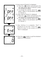
5. State of One-time system is displayed.
on: Recording stops when memory becomes full
off: Overwrite the old data, and store the latest
data.
button and proceed to the
¡ Press the
next step when not changing the setting.
¡ To change the setting, press the
button.
Then the indication on the LCD flashes. Press
the
or
button to set the value to
the desired one. Then press the
button
to confirm it.
6. Now Setting 1 is complete; "End" is displayed
on the LCD. Press the
button to return
to the screen on which "SEt.1" is displayed.
7. Press the
button to get the instrument
ready for a measurement.
㩷
― 24 ―
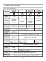
6. Recording modes
List of recording modes
Continuous
recording
Event recording
Max. value
recording
Capture
recording
Details
P.26
P.27
P.28
P.29
To check:
Condition,
Intermittent
leakage
Occurrence of
leakage
Intermittent
leakage,
Occurrence of
leakage
Waveform
Can record:
60,000 data(1ch)
20,000 data(3ch)
4,800 data(1ch)
1,600 data(3ch)
990 data(1ch)
330 data(3ch)
345 data
Recording
mode
Available CH
Recording
interval
Pre-set
current value
3 channels at the same time
15-kind:
1 sec. to 60 min.
----
----
0∼1000mA (can be set at every 1mA)
Sampling
period
Pre-set recording
interval
(intermittent
measurement)
At 50Hz:
approx. 0.222mS
At 60Hz:
approx. 0.185mS
For 2 cycles
(50Hz: for 40mS)
Record
timing
At every recording
interval
Measureme
nt interval
Sampling
cycle
Measuring
method
One-time
system
Battery life
CH1 only
True RMS
Approx. 0.1 sec. (constant)
Current detection:
approx. 1.67mS
RMS:
approx. 3.33mS
Current detection:
approx. 0.56mS
RMS:approx.
1.11mS
Constantly until current detection
When the pre-set current value is exceeded. (irregular)
Current detection:
Average value (Convert the Peak value (sine) to RMS)
Record/Display: True RMS
O N : Recording stops when memory becomes full.
OFF: Overwrite the old data, and store the latest data.
Approx. 25 days (M-5000)/ Approx. 40 days (M-5001)
― 25 ―
(1)
Continuous recording mode
¡ Sampling period and RMS calculation
The input signal obtained via the connected sensor is sampled (at
50Hz,approx 0.222mS; at 60Hz, approx. 0.185mS) just for 2-cycle
(180 data). Then RMS value is calculated by the sampled 180 data.
The instrument goes into stand-by mode till next recording interval
comes.
¡ Recording
The channels to which each sensor is being connected are switched
in sequence at recording interval. Then RMS values are found by
sampling the data for 2-cycle at each channel and recorded.
¡ Display of measured value
At measurement state before a recording, the measured value is
displayed on the LCD at every 1 sec..
― 26 ―
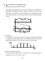
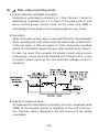
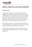
(2)
Event recording mode
¡ Current detection and RMS calculation
Sampling is performed consistently at 1.6ms intervals. Current is
detected by comparing the 1/√2 times of the peak value of sine
wave and the preset current value. At the same time, RMS is
calculated at 100ms based on the sampling data at every 3.3ms.
¡ Recording
When the preset current detection value is exceeded (Point A), the
instrument records 8 data points including:
- 3 RMS values prior to the cross over point
- RMS value at the cross over point
- 4 RMS values subsequent to the cross over point.
The peak value when detecting is recorded with time information.
In case the event that exceeds the current detection value occurs
continuously, current will not be detected until it drops to 50% or less
of preset current value as the last detected leakage current is
remaining.
¡ Display of measured value
At measurement state before a recording, the max. measured value
(RMS) at the selected channel is displayed on the LCD at every 1
sec..
― 27 ―
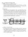
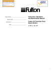
(3)
Max. value recording mode
¡ Current detection and RMS calculation
Sampling is performed consistently at 1.6ms intervals. Current is
detected by comparing the 1/√2 times of the peak value of sine
wave and the preset current value. At the same time, RMS is
calculated at 100ms based on the sampling data at every 3.3ms.
¡ Recording
When the preset current value is exceeded (Point A), the instrument
starts recording and ends either when the value drops to below 50%
of the set value, or after an elapse of 10min. During the recording
period, the instrument records the max value reached every 10secs.
In case the event that exceeds the preset current value occurs
continuously, current will not be detected until it drops to 50% or less
of preset current value as the last detected leakage current is
remaining.
¡ Display of measured value
At measurement state before a recording, the max. measured value
(RMS) at the selected channel is displayed on the LCD at every 1
sec.. The max. value is displayed on the LCD at every 10 sec. during
a recording.
― 28 ―
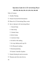
(4)
Capture recording mode
¡ Current detection and RMS calculation
Sampling is performed consistently only at Channel 1 at 1.6ms
intervals. Current is detected by comparing the 1/√2 times of the
peak value of sine wave and the preset current value.
¡ Recording
When the preset current detection value is exceeded (Point A),the
instrument records instantaneous values with corresponding time
information for 200ms(10 to 12 waveforms) including 50ms prior to
and subsequent to the cross over point. In case the event that
exceeds the current detection value occurs continuously, current will
not be detected until it drops to 50% or less of preset current value
as the last detected leakage current is remaining.
¡ Display of measured value
At measurement state before a recording, the max. measured
value (RMS) at Channel 1 is displayed on the LCD at every 1 sec..
(* Waveform cannot be displayed on the LCD of the instrument.
Transfer the data to PC by using PC software of accessory, and
check the graphic display.)
― 29 ―
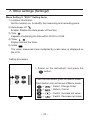
7. Other settings (Setting2)
Menu Setting 2: "SEt.2" Setting items
1) Location information
Set the location no. to identify the measuring and recording place.
2) Auto-power-off
Enable/ Disable the Auto-power-off function.
3) Time
Capable of adjusting the time within 00:00 to 23:59.
4) Timer
Display and set the timer.
5) Scale
The value: measured value multiplied by scale value, is displayed on
the LCD.
Setting procedure
1. Power on the instrument, and press the
button.
Then the instrument goes into Menu mode.
Each button acts as follows at Menu mode.
→
:Select, Change, Enter
→
:Return, Cancel
㩷
→
:Switch, Increase set value
→
:Switch, Decrease set value
― 30 ―
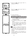
㩷
2. Press the
button when "SEt.1" is
displayed on the LCD.
㩷
㩷
3. Press the
button when "SEt.2" is
displayed on the LCD.
㩷
㩷
㩷
㩷
4. "Location information":
The location no. is displayed.
Can be selected between "P.000" and "P.999".
button and proceed to
¡ Press the
the next step (Auto-power-off) when not
changing the setting.
¡ To change the setting, press the
button.
Then the indication on the LCD flashes.
Press the
or
button to set
the value to the desired one. Then press
the
button to confirm it.
Note Location no. is linked to the location list in
PC Software and allows to display the
location name, which corresponding to the
location no., when displaying data on PC
software.
In case of setting it on the instrument, it is
recommended to take notes of the location
no. and the name.
― 31 ―
5. "Auto-power-off":
State of Auto-power-off function is displayed.
O n : Enables Auto-power-off function.
OFF : Disables Auto-power-off function.
button and proceed to
¡ Press the
the next step (Time) when not changing
the setting.
¡ To change the setting, press the
button.
Then the indication on the LCD flashes.
Press the
or
button to set
the value to the desired one. Then press
the
button to confirm it.
mark is displayed on the LCD
Note The
when the Auto-power-off function is disabled.
Be sure to power off the instrument after use.
When it is enabled, instrument is powered off
automatically when 3 min has been elapsed
after the last operation of keys. During a
recording, indications on the LCD disappear
automatically for saving the battery life,
however, a recording is being performed.
6. "Time": Time is displayed.
Can be adjusted within "00:00" to "23:59".
button and proceed to
¡ Press the
the next step (Timer) when not changing
the setting.
¡ To change the setting, press the
button.
Then the indication on the LCD flashes.
Press the
or
button to set
the value to the desired one. Then press
the
button to confirm it.
Note Connect the instrument to PC and set
time and date via PC software "KEW LOG
Soft".
― 32 ―
㩷
㩷
7. "Timer": State of Timer function is displayed.
Can be set within "00:00" to "23:59".
button and proceed to
¡ Press the
the next step (Scale) when not changing
the setting.
¡ To change the setting, press the
button.
Then the indication on the LCD flashes.
Press the
or
button to set
the value to the desired one. Then press
the
button to confirm it.
" button at least 1 sec.
Note Press the "
after setting. Then the instrument goes into
stand-by mode for recording. Recording
starts at the preset time.
㩷
8. "Scale": Scale value at Channel 1 is
displayed.
Can be set within "0.1" to "10.0". (1.0: OFF)
button and proceed to
¡ Press the
the next step (Scale value at Channel 2)
when not changing the setting.
button.
¡ To change the setting, press the
Then the indication on the LCD flashes.
Press the
or
button to set
the value to the desired one. Then press
the
button to confirm it.
Note When measuring one-tenth signal via
Multi-tran or something, if the scale value is
set to 10.0; measured value can be directly
read from the LCD as it is displayed :
Measured value x 10.0 = Indicated value. (It
will not be reflected on the recorded data.)
* e.g.: Set "10.0" at CH 1. Then "150.0mA" is
displayed as a measured value when
measuring 15.0mA at CH 1.
㩷
㩷
― 33 ―
㩷
9. Scale value at Channel 2 is displayed.
button and proceed to the
¡ Press the
next step (Scale value at Channel 3) when
not changing the setting
¡ To change the setting, press the
button. (Refer to the procedure described
for Channel 1.)
10. Scale value at Channel 3 is displayed.
button and proceed to the
¡ Press the
next step when not changing the setting.
¡ To change the setting, press the
button. (Refer to the procedure described
for Channel 1.)
㩷
11. Now Setting 2 is complete; "End" is
displayed on the LCD. Press the
button to return to the screen on which
"SEt.2" is displayed.
㩷
㩷
12. Press the
button to get the instrument
ready for a measurement.
㩷
― 34 ―
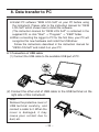
8. Data transfer to PC
¡IInstall PC software "KEW LOG Soft" on your PC before using
the instrument. Please refer to the instruction manual for "KEW
LOG Soft" which shows how to install the software.
(The instruction manual for "KEW LOG Soft" is contained in the
supplied CD; or click "Start" → "Program" → "KEW" folder.
¡When connecting the logger to PC for the first time, your PC will
recognize this new hardware and install the USB driver.
Follow the instructions described in the instruction manual for
"KEW LOG Soft" and install it on your PC.
8-1 Connection of USB cable
(1) Connect the USB cable to the available USB port of PC.
(2) Connect the other end of USB cable to the USB terminal on the
right side of this instrument.
Note:
Remove the protective cover of
USB terminal carefully, and
connect a cable to it. When the
cover is damaged, it may
cause poor contact due to
dust, etc.
― 35 ―
8-2 Preparation for data transmission
(1) Power on the instrument, and get the instrument ready for a
measurement.
(Note: Data cannot be transferred while the instrument is
performing a recording.)
(2) Start up the PC software: KEW LOG Soft.
8-3 Operation of PC software
Refer to the supplied instruction manual for "KEW LOG Soft" and
transfer the data to your PC. The PC may not detect the connected
Logger or error message is displayed during data transfer, even if the
PC and the Logger are connected correctly because of static
electricity.
In this case, a message is displayed on the PC screen. Please
disconnect/ connect the USB cable once accordingly, and transfer
the data again.
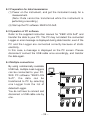
8-4 Multiple connections
By using commercially available
USB hub, multiple Leak Loggers
can be connected to your PC.
With PC software "KEW LOG
Soft", the data can be
transferred to PC by selecting
one Logger from the list of
detected Logger.
You do not have to connect and
disconnect a USB cable one by
one.
― 36 ―
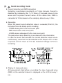
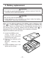
9. Battery replacement
WARNING
¡In order to avoid electrical shock, remove sensors from the
instrument when replacing batteries.
CAUTION
¡Do not mix new and old batteries.
¡ Install batteries in the orientation as shown inside the battery
compartment, observing correct polarity.
When only the leftmost segment of the Battery mark is flashing on the
LCD
, it means battery voltage is low. Replace the batteries with
new ones. There is no influence on the measurement accuracy even if
this warning mark is flashing. Nothing even the Battery mark
is
displayed on the LCD if the batteries are completely exhausted.
Replace the batteries with new ones.
(1) Loosen two Battery-cover
-fixing screws on the
backside of the instrument
and remove the cover.
(2) Replace the batteries with
new ones.
(Battery : Alkaline, LR6,
1.5V)
(3) Install the Battery cover, and
tighten up the screws.
― 37 ―
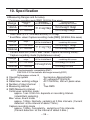
10. Specification
¡Measuring Ranges and Accuracy
* Continuous recording mode [RMS] (50/60Hz,Sine wave)
Measuring
Accuracy when
Accuracy
Range
range
combining with sensor
of the instrument
100mA
0∼100.0mA
1000mA
0∼1000mA
±1.0%rdg±5dgt
±2.0%rdg±10dgt
±2.0%rdg±6dgt
Crest Factor ≦ 2.5 : Sine wave accuracy +2%+5dgt
* Event/Max. value/ Capture recording mode [RMS] (50/60Hz,Sine wave)
Range
Measuring
range
100mA
0∼100.0mA
1000mA
0∼1000mA
Accuracy
of the instrument
±1.5%rdg±7dgt
Accuracy when
combining with sensor
±2.5%rdg±12dgt
±2.5%rdg±8dgt
* Current detection (Event/ Max. value/ Capture recording mode):
* Capture recording mode [instantaneous value]:
Range
Measuring
range
100mA
0∼100.0mA
1000mA
0∼1000mA
Accuracy
of the instrument
±3%rdg±2%fs
Accuracy when
combining with sensor
±4%rdg±2.5%fs
±4%rdg±2%fs
NOTE: Electromagnetic compatibility(EMC)
EN61000-4-2 Electrostatic discharge immunity(ESD)
Performance criteria: B
:
Successive Approximation
¡ Operating system
:
AC voltage(AC100mV/A)
¡ Input
AC170mVrms, 250mV peak value
¡ Rated max. working voltage :
3
¡ Number of input channel :
:
True RMS
¡ Measuring method
:
¡ RMS Measuring interval
Continuous recording mode:
approx. 1sec. to 60 min. depends on recording Interval.
(intermittent sampling)
Max. value, Event mode
:
approx. 100ms. Normally, sampling at 3.3ms intervals. (Current
detection: at the interval of about 1.6ms.)
Capture recording mode
:
approx. 100ms. Consistently , sampling at 1ms intervals.
(Current detection: at the interval of about 0.5ms.)
― 38 ―
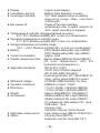
¡ Display
¡ Low battery warning
¡ Overrange indication
: Liquid crystal display
: Battery mark display(in 4 levels)
: "OL" mark appears when exceeding
measuring range. (Max. indication
1049counts.)
: Power off function operates
¡Auto power off
automatically after a switch remains for
3min. (when recording is stopped)
¡ Temperature & humidity range(guaranteed accuracy) :
23℃±5℃/Relative humidity 85% or less (no condensation)
¡ Operating temperature & humidity range :
0℃∼50℃/Relative humidity 85% or less (no condensation)
¡ Storage temperature & humidity range :
-20℃∼+60℃/Relative humidity 85% or less (no condensation)
: DC6V: Alkaline battery(LR6) x 4pcs (M5000)
¡ Battery
DC9V: Alkaline battery(LR6) x 6pcs (M5001)
: approx. 5mA
¡ Current consumption
¡ Possible measurement time :Approx.25days(M5000)/40days(M5001)
(At room temperature, until the
instrument isnot powered on.)
: IEC 61010-1:2001
¡ Applicable standards
CATIII 300V Pollution degree2
IEC 61326 (EMC standard)
Overload protection: AC 1500A MAX/ for
10sec. (when sensor M8143 is used.)
: AC3536V (RMS 50/60Hz)/ for 5sec.
¡ Withstand voltage
: 50Mohm or more / 1000V
¡ Insulation resistance
: 111(H) x 60(W) x 36(D)mm (M5000)
¡ Dimension
111(H) x 60(W) x 42(D)mm (M5001)
: Approx.255g(M5000)/ 315g(M5001)
¡ Weight
: Alkaline battery LR6 x 4pcs (M5000)
¡ Accessories
Alkaline battery LR6 x 6pcs (M5001)
PC software for data display CD : 1pce
USB cable : 1pce.
Carrying case
Instruction manual, Quick manual
¡ Applicable clamp sensor : Leak clamp sensor (M8141/8142/8143)
: Carrying Case (M9119)
¡ Option
Extension cord for sensor(M-7147)
― 39 ―
MEMO
― 40 ―
MEMO
― 41 ―
DISTRIBUTOR
Kyoritsu reserves the rights to change specifications or designs
described in this manual without notice and without obligations.
KYORITSU ELECTRICAL
INSTRUMENTS
WORKS, LTD.
No.5-20, Nakane 2― chome, Meguro-ku,
Tokyo, 152-0031 Japan
Phone: 81―3―3723― 0131 Fax: 81―3―3723― 0152
URL:http://www.kew-ltd.co.jp
E-mail:[email protected]
Factories:Uwajima&Ehime
04-06
92-1599B