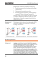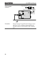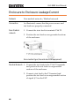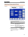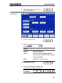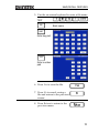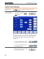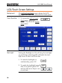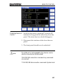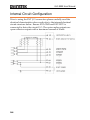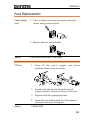
1
99 Washington Street
Melrose, MA 02176
Phone 781-665-1400
Toll Free 1-800-517-8431
Visit us at www.TestEquipmentDepot.com
LEAKAGE CURRENT TESTER
GLC-9000
USER MANUAL
GWINSTEK PART NO.:82LC-90000M01
ISO-9001 CERTIFIED MANUFACTURER
This manual contains proprietary information, which is protected by
copyright. All rights are reserved. No part of this manual may be
photocopied, reproduced or translated to another language without
prior written consent of Good Will Corporation.
The information in this manual was correct at the time of printing.
However, Good Will continues to improve its products and therefore
reserves the right to change the specifications, equipment, and
maintenance procedures at any time without notice.
Good Will Instrument Co., Ltd.
No. 7-1, Jhongsing Rd., Tucheng City, Taipei County 236, Taiwan.
SAFETY INSTRUCTIONS
Table of Contents
SAFETY INSTRUCTIONS ................................7
Safety Symbols ................................................................... 7
Safety Guidelines................................................................ 8
Power cord for the United Kingdom.................................. 11
OVERVIEW.................................................. 13
Introduction ................................................................... 13
Leakage Current Modes.................................................... 14
Measurement Principles................................................... 15
Measuring Devices ........................................................... 16
Key Features...................................................................
Basic Theory...................................................................
Leakage Current Modes ..................................................
Leakage Current Modes ..................................................
Measurement Flow Chart ................................................
Front Panel ....................................................................
Rear Panel......................................................................
Touch Screen Basics .......................................................
19
22
24
29
30
31
33
35
GETTING STARTED ..................................... 37
Preparation ....................................................................
Power and Probe Connection ..........................................
Power Up .......................................................................
Shut Down .....................................................................
37
38
41
42
OPERATION................................................ 43
Measurement terminals .................................................. 43
Non-medical network (General electrical appliance)......... 43
Medical Equipment .......................................................... 44
Earth Leakage Current .................................................... 44
Enclosure Leakage Current.............................................. 46
Enclosure to Enclosure Leakage Current .......................... 48
3
GLC-9000 User Manual
Enclosure and line leakage current ...................................50
Patient Auxiliary Current ..................................................52
Patient Leakage Current I.................................................53
Patient Leakage Current II ...............................................55
Patient Leakage Current III ..............................................56
MEASUREMENT ......................................... 59
Interface .........................................................................59
Selecting the Safety Class/ Grounding Class.....................63
Selecting a Measuring Network........................................64
Selecting a Measurement Mode .......................................65
Selecting Measurement Parameters .................................66
Setting the Limits.............................................................. 66
Auto/Manual Measurement Functions ............................. 67
Setting Leakage current type ............................................. 70
Setting the range............................................................... 71
Saving Measurement Results ...........................................73
SAVE/RECALL FEATURES............................. 75
Save Settings ..................................................................75
Recall Panel Settings or Data ...........................................78
USB Storage ............................................... 83
Connection and Navigation..............................................83
Copy files to USB .............................................................. 85
Firmware Update .............................................................. 86
Save a screen image.......................................................... 87
SYSTEM SETTINGS ..................................... 89
Alarm/Tone Settings ........................................................90
Date and Time Settings ...................................................91
Language Selection .........................................................92
System Self Test ..............................................................93
LCD/Touch Screen Settings..............................................94
EUT Voltage and Current Check........................................96
Interface .........................................................................97
4
SAFETY INSTRUCTIONS
Voltage Measurement ..................................................... 99
Sytem Initialization .......................................................102
Version and Serial Number ............................................103
REMOTE CONTROL .................................. 105
Remote Control Settings ................................................105
Remote Connection .......................................................106
Command Syntax...........................................................108
Command List ...............................................................112
Measurement Network Commands.................................112
Measuring Equipment configuration commands.............112
Measurement Mode commands......................................112
Measurement Command.................................................112
Manual Measurement Commands ..................................113
Automatic Measurement commands...............................113
Measurement commands................................................113
Measurement Data commands .......................................113
Save Data commands......................................................114
System Setup commands ................................................114
System Related commands .............................................115
RS232 Interface commands.............................................115
IEEE488.2 Interface commands .......................................115
Commands....................................................................117
Measurement Network Commands.................................117
Measuring Equipment configuration Commands ............118
Measurement Mode Command.......................................119
Measurement Commands...............................................120
Measurement Items ........................................................121
Manual Measurement commands...................................123
Automatic Measurement Commands..............................128
Measurement Command.................................................130
Measurement Data Command ........................................131
Save Data Command.......................................................132
System Setup Command .................................................135
System Related Commands.............................................145
RS232 Interface Command..............................................147
SCPI Status Registers ....................................................148
Event Registers................................................................149
Enable Registers............................................................149
Status Byte Register.......................................................150
Standard Event Register.................................................152
5
GLC-9000 User Manual
Status Byte Register Command ...................................... 153
Standard Event Register Commands............................... 154
Other Status Register Commands .................................. 155
Errors ........................................................................... 156
Command Errors ............................................................ 156
Execution Errors.............................................................. 158
Device Specific Errors ..................................................... 158
EXTERNAL I/O.......................................... 159
Features ........................................................................ 159
Cautions ....................................................................... 159
I/O Definition ............................................................... 160
Connection.................................................................... 162
Electrical Characteristics................................................ 163
Input Signals .................................................................. 163
Output signal.................................................................. 163
Internal Power Supply..................................................... 163
Internal Circuit Configuration ........................................ 164
Timing Description........................................................ 165
FAQ ......................................................... 167
APPENDIX................................................ 169
Measurement Functions ................................................ 169
Specifications................................................................ 171
Accessories ................................................................... 172
Measurement Network (MD) ......................................... 173
Fuse Replacement ......................................................... 175
Battery Replacement...................................................... 176
Declaration of Conformity.............................................. 177
INDEX...................................................... 179
6
SAFETY INSTRUCTIONS
SAFETY INSTRUCTIONS
This chapter contains important safety instructions that you must
follow when operating or storing a GLC-9000 series current leakage
tester. Following these instructions will ensure your safety and keep
the instrument in the best possible condition.
Safety Symbols
These safety symbols may appear in this manual or on the
instrument.
WARNING
Warning: Identifies conditions or practices that
could result in injury or loss of life.
CAUTION
Caution: Identifies conditions or practices that
could result in damage to the instrument or to
other properties.
DANGER High Voltage
Attention Refer to the Manual
Protective Conductor Terminal
Earth (ground) Terminal
Do not dispose electronic equipment as unsorted
municipal waste. Please use a separate collection
facility or contact the supplier from which this
instrument was purchased.
7
GLC-9000 User Manual
Safety Guidelines
General
Guideline
CAUTION
•
Do not place any heavy object on the
instrument.
•
Avoid severe impact or rough handling that
leads to damaging the instrument.
•
Do not discharge static electricity to the
instrument.
•
Do not block or obstruct the cooling fan vent
opening.
•
Do not perform measurement at circuits
directly connected to Mains (Note below).
•
Do not disassemble the instrument unless you
are qualified as service personnel.
(Measurement categories) EN 61010-1:2001 specifies the
measurement categories and their requirements as follows. the
GLC-9000 falls under category I
Power Supply
WARNING
Fuse
WARNING
8
•
Measurement category IV is for measurement performed at the
source of low-voltage installation.
•
Measurement category III is for measurement performed in the
building installation.
•
Measurement category II is for measurement performed on the
circuits directly connected to the low voltage installation.
•
Measurement category I is for measurements performed on
circuits not directly connected to Mains.
•
AC Input voltage:100V/120V/220V/230V
±10%, 50/60Hz
•
Connect the protective grounding conductor of
the AC power cord to an earth ground, to avoid
electrical shock.
•
Fuse type: T0.4A/250V
•
Make sure the correct type of fuse is installed
before power up.
SAFETY INSTRUCTIONS
Cleaning the
GLC-9000
Operation
Environment
•
To ensure fire protection, replace the fuse only
with the specified type and rating.
•
Disconnect the power cord before fuse
replacement.
•
Make sure the cause of fuse blowout is fixed
before fuse replacement.
•
Disconnect the power cord before cleaning.
•
Use a soft cloth dampened in a solution of mild
detergent and water. Do not spray any liquid.
•
Do not use chemical or cleaner containing harsh
material such as benzene, toluene, xylene, and
acetone.
•
Location: Indoor, no direct sunlight, dust free,
almost non-conductive pollution (Note below)
•
Relative Humidity: < 80%
•
Altitude: < 2000m
•
Temperature: 0°C to 40°C
(Pollution Degree) EN 61010-1:2001 specifies the pollution degrees
and their requirements as follows. The GLC-9000 falls under degree
2.
Pollution refers to “addition of foreign matter, solid, liquid, or
gaseous (ionized gases), that may produce a reduction of dielectric
strength or surface resistivity”.
Storage
environment
•
Pollution degree 1: No pollution or only dry, non-conductive
pollution occurs. The pollution has no influence.
•
Pollution degree 2: Normally only non-conductive pollution
occurs. Occasionally, however, a temporary conductivity caused
by condensation must be expected.
•
Pollution degree 3: Conductive pollution occurs, or dry, nonconductive pollution occurs which becomes conductive due to
condensation which is expected. In such conditions, equipment
is normally protected against exposure to direct sunlight,
precipitation, and full wind pressure, but neither temperature
nor humidity is controlled.
•
Location: Indoor
•
Relative Humidity: < 70%
•
Temperature: −10°C to 70°C
9
GLC-9000 User Manual
Disposal
10
Do not dispose this instrument as unsorted
municipal waste. Please use a separate collection
facility or contact the supplier from which this
instrument was purchased. Please make sure
discarded electrical waste is properly recycled to
reduce environmental impact.
SAFETY INSTRUCTIONS
Power cord for the United Kingdom
When using a GLC-9000 series current leakage tester in the United
Kingdom, make sure the power cord meets the following safety
instructions.
NOTE: This lead/appliance must only be wired by competent persons
WARNING: THIS APPLIANCE MUST BE EARTHED
IMPORTANT: The wires in this lead are coloured in accordance with the
following code:
Green/ Yellow:
Earth
Blue:
Neutral
Brown:
Live (Phase)
As the colours of the wires in main leads may not correspond with the
coloured marking identified in your plug/appliance, proceed as follows:
The wire which is coloured Green & Yellow must be connected to the Earth
or coloured
terminal marked with either the letter E, the earth symbol
Green/Green & Yellow.
The wire which is coloured Blue must be connected to the terminal which is
marked with the letter N or coloured Blue or Black.
The wire which is coloured Brown must be connected to the terminal
marked with the letter L or P or coloured Brown or Red.
If in doubt, consult the instructions provided with the equipment or contact
the supplier.
This cable/appliance should be protected by a suitably rated and approved
HBC mains fuse: refer to the rating information on the equipment and/or
user instructions for details. As a guide, a cable of 0.75mm2 should be
protected by a 3A or 5A fuse. Larger conductors would normally require
13A types, depending on the connection method used.
Any exposed wiring from a cable, plug or connection that is engaged in a
live socket is extremely hazardous. If a cable or plug is deemed hazardous,
turn off the mains power and remove the cable, any fuses and fuse
assemblies. All hazardous wiring must be immediately destroyed and
replaced in accordance to the above standard.
11
OVERVIEW
OVERVIEW
This chapter describes the GLC-9000 in a nutshell, including the
main features, front and rear panel description, and the power up
sequence.
Introduction
Overview
Many electrical products must undergo electrical
safety testing to ensure their safety. These tests
include insulation resistance, withstand voltage,
ground continuity and leakage current tests. These
tests are complex and critical for safety standards
compliance.
To comply with international standards and to
ensure operator safety, leakage current tests are
also performed under normal and faulty operating
conditions.
Leakage current tests can be separated into 3 basic
types:
•
Earth Leakage current
•
Enclosure Leakage current
•
Patient Leakage current
The GLC-9000 complies with IEC, UL and other
international electrical safety standards requiring
leakage current measurement.
13
GLC-9000 User Manual
Leakage Current Modes
1.
Earth
Leakage
Current
Refers to the current that flows through a
protective grounding wire to earth. (General
Electrical, Medical Equipment)
2.
Enclosure
Leakage
Current
Refers to the current that flows through a human
body in contact with a device enclosure. (General
Electrical, Medical Equipment)
3.
Patient
Leakage
Current I
Refers to the current that flows through a human
body that is directly connected to a device.
(Medical Equipment)
4.
Patient
Leakage
Current II
Refers to the current that flows through a human
body that is directly connected to a device under
faulty conditions. (Medical Equipment)
14
OVERVIEW
5.
Patient
Leakage
Current III
Refers to the current that flows through a human
body that is directly connected to a device that
malfunctions. (Medical Equipment)
6.
Patient
Auxiliary
Current
Refers to the current that flows through a human
and a device during normal operation. This is not
intended to be perceptive. (Medical Equipment)
Measurement Principles
Background
Leakage current can be categorized into 3 types:
Electric current that flows through the body of
someone who touches the equipment, the current that
flows through a protective grounding wire to earth and
the current that flows through a human body
connected to an applied part. When testing the
leakage current of an EUT (equipment under test),
testing must be performed under normal and single
fault conditions.
As shown below, a number of relays are used to
simulate different fault conditions. Power to the EUT
is normally open and thus turning off the power
disconnects one wire on the power line.
15
GLC-9000 User Manual
Single Fault conditions include the following:
1.
Earth disconnected (excluding earth leakage
current tests).
2.
Disconnected neutral power line.
3.
External equipment failure. (Patient leakage
current II, Patient Leakage Current III).
Polarity of the power supply can also be switched
to measure the leakage current under test. Thus
the polarity of the power supply should also be
taken into account.
Measurement
Methods
The diagram below shows how the probes, MD’s
and power supply are connected for different
leakage current tests.
Measuring Devices
Background
16
Leakage current (touch current) tests that measure
electrical equipment require a circuit network that can
simulate the impedance of a human body. The
impedance of a human body varies with the contact
points, area and the path of conduction. Thus the
circuit network used to simulate the impedance of a
human body varies with the type of test performed. As
such, the safety standards used to measure leakage
current also varies greatly. The circuit networks used
are known as measuring devices, or MD for short. MD
OVERVIEW
circuits are resistor-capacitor (RC) circuits. The GLC9000 supports 9 different measuring devices.
IEC60990s
MD-A
JIS Standards
MD-I
MD-B
General Purpose MD-E
MD-H
UL Standards
Md-D
MD-G
Medical
Networks
MD-F
MD-C
17
GLC-9000 User Manual
Note
When conducting leakage current tests, please note
the following:
1.
Under normal operating conditions,
leakage current is measured when an electrical
device under test is properly insulated with earth.
If the device is not properly insulated, the leakage
current that is conducted through the
measurement network may be invalid.
2.
Leakage current tests involve high
voltages. When working with high voltages,
testing personnel should use proper safety
precautions. All test labs should establish safety
rules to cut-off power to an EUT should conditions
become unsafe. Contacting any electrical appliance
under test is extremely hazardous and should not
be attempted.
3.
The surrounding environment has an
effect upon leakage current tests. Avoid high
temperatures, high humidity and surface
pollutants on the enclosure surface as they can all
have an influence on the resulting data.
18
OVERVIEW
Key Features
International
Standards and
Regulations
The GLC-9000 has nine measurement networks
(Measuring Devices: MD) supporting GB/12113,
IEC/UL and other international standards for
electrical products:
(1) MD-A:IEC60990
(2) MD-B:IEC60990
(3) MD-C:IEC60990
(4) MD-D:UL
(5) MD-E(1kΩ):-general application
(6) MD-F: Medical
(7) MD-G:UL
(8) MD-H:(2kΩ)-general application
(9) MD-I:JIS
Measurement
Modes
There are a number of leakage current
measurement tests covering general electrical
equipment and medical electrical equipment.
(1)
(2)
(3)
(4)
(5)
(6)
(7)
(8)
Earth Leakage Current.
Leakage current from enclosure and earth.
Leakage current from enclosure to enclosure.
Leakage current from enclosure to line.
Patient Auxiliary Current*.
Patient leakage current I*.
Patient leakage current II*.
Patient leakage current III*.
*Tests 5,6,7,8 are applicable to medical MD-F
devices.
Leakage Current
Types
Leakage current measurement modes:
DC, AC, AC+DC, AC Peak.
19
GLC-9000 User Manual
Measurement
Range
Automatic/Manual ranges:
DC/AC/AC+DC:50uA/500uA/5mA/25mA
(Range:4uA~25mA)
AC Peak:500uA/1mA/10mA/75mA
(Range:40uA~75mA)
Operation
•
Auto/Manual/Programmable
Single fault conditions and power supply
polarity switch
•
Measurement/Delay time settings
•
Maximum / minimum hold
•
PASS/FAIL(Upper, Lower) Judgement (limits)
•
save and recall setup and measurement results
•
System clock settings
•
Multilanguage support
•
System Self test
•
EUT voltage/current/power consumption
•
High output alarm and led indicators.
•
Remote control interface options
Interface
With the exception of the Start, Reset and power
switches, the user-interface is entirely controlled
via a touch screen.
LCD
The simple, user-friendly interface is extremely
intuitive with a large 5.6” color TFT screen.
EUT Test Status
The voltage, current and power consumption of
the EUT can be measured.
Built-in Voltage
Meter
The built in voltage meter detects 0-300V. The
voltage meter is activated when the Safety Extra
Low Voltage (SELV) function is on.
20
OVERVIEW
Memory
•
30 sets of memory for user defined test
conditions
•
50 sets of standard test conditions.
(e.g., IEC60990)
•
100 sets of measurements can be saved/recalled
Remote Interface There are a variety of remote control interfaces
including: RS-232, USB(Host/Device)and
GPIB.
Protection
The LED warning indicator will illuminate and
emit a tone by default for:
•
Judgment limits. (high/low limits).
•
High Voltages output from the testing
terminals.
•
Overload protection (fuse protection).
•
Relay protection for EUT overloads.
21
GLC-9000 User Manual
Basic Theory
Overview
•
GLC-9000 consists of the following blocks as
illustrated in the figure below.
•
Tester and EUT power supply
•
MD (Measuring Device) circuit network
•
Current detection
•
Signal Process
•
CPU/Digital control
•
User I/O
•
Remote control interfaces
Block Diagram
EUT IN
MD Network
LCD,
Alarm
Interfaces
RS-232、
USB、
GPIB、
LINE IN
Power
Equipment
Under Test
EUT Power
Switching
CPU
Digital
control
Probe
表
Current
Detection
Signal Process
Tester
Power
Tester Power: Provides the power for tester
circuits.
EUT Power: Provides an isolated power source to
EUT.
22
OVERVIEW
EUT Power
Switching
This switching matrix controls relays to alter the
EUT power to simulate a number of different test
conditions, such as earth open or reverse polarity,
etc.
MD Network
Different MD networks represent different
equivalent circuits of a human body. They are
chosen according to different regulations.
Probe
Probes are used to simulate a human-touch-point
on the EUT. The leakage current flows through the
probe and is measured.
Current detection Detects and measures the different leakage current
& signal process. types (AC,DC,…)
CPU and digital
control
CPU, digital circuits and memory.
LCD/
Alarm/Button
The touch-screen LCD, buttons and alarm are
controlled by the CPU for user input and display.
Interfaces
Interfaces allow remote control via RS232, GPIB
and USB.
23
GLC-9000 User Manual
Leakage Current Modes
Definition
As illustrated below, the leakage current generated
with a high voltage in an electrical appliance
requires measurement under normal EUT
(Equipment Under Test) conditions and under
single fault conditions. Leakage current can be
categorized into 3 types: Electric current that flows
through the body of someone who touches the
equipment, the current that flows through a
protective grounding wire to earth and the current
that flows through a human body connected to an
applied part.
Leakage current can be composed of either
conduction current that flows thru insulation
resistance, or displacement current that flows thru
distributed capacitance.
Earth Leakage
Current
Description
Earth Leakage Current Tests measure the current
that flows from a protective grounding wire
through a human body to earth.
Class I equipment requires the protective
grounding wire to be disconnected under single
fault conditions.
24
OVERVIEW
Leakage current can be dangerous and produce
shocks over a certain limit.
Enclosure and
Earth leakage
current
EUT
Enclosure and Earth
Leakage Current
Description
During normal conditions, an operator or a patient
is expected to touch the enclosure of an instrument
(except for applied parts). The enclosure and earth
leakage current test measures the leakage current
that flows through a human body to earth when in
contact with the instrument enclosure.
For class II equipment, enclosures are ungrounded,
and must be tested for leakage current that flows
through a human body impedance network to
earth. This test also applies to Class I equipment
where the enclosure is not grounded.
25
GLC-9000 User Manual
Enclosure and
Enclosure
Leakage Current
EUT
Enclosure and
Enclosure Leakage
Current
Description
Under normal or single fault conditions, the
leakage current that flows through a human body
from any 2 isolated parts of the enclosure.
Patient Leakage
Current I
EUT
Applied Part
Patient Leakage Current 1
Description
26
Patient Leakage Current I is the leakage current
that flows through a person connected to an
applied part to earth.
OVERVIEW
Patient Leakage
Current II
Description
Patient leakage current II refers to the current that
flows from an applied part through a human body
to earth. For the test it is assumed that an external
I/O device that is connected to the signal input of
the EUT malfunctions with an output of 110% of
the rated voltage.
27
GLC-9000 User Manual
Patient Leakage
Current III
Faulty Equipment
Patient Leakage Current 3
Applied Part
EUT
Description
28
Patient Leakage Current III is the leakage current
that flows from a malfunctioning applied part,
through a person, and through a Type F applied
part.
OVERVIEW
Leakage Current Modes
Type
Single
Normal
Condition Fault
Fault Description
Notes
Power line disconnected.
Class 1
only
Earth Leakage
Current
Yes
Yes
Enclosure to
Earth leakage
current
Yes
Yes
Enclosure to
Enclosure
leakage current
Yes
Yes
Enclosure to
line leakage
current.
Yes
Yes
Patient Auxiliary
Current
Yes
Yes
1. Power Line
disconnected.
Patient Leakage
Current I
Yes
Yes
2. Earth disconnected*.
Patient Leakage
Current II
Patient Leakage
Current III
1. Power line
disconnected.
Class 1
only*
2. Disconnected earth
protection*.
No
No
3.110% of the rated power
supply voltage applied
to the signal
input/output parts and
earth.
Class 1
only*
Yes
110% of the rated
Type B
power supply voltage applied
applied to the signal
part
input/output parts and
earth.
Yes
110% of the rated
Type F
power supply voltage applied
is applied to the F-type part
applied part and earth.
29
GLC-9000 User Manual
Measurement Flow Chart
Start
Reference
Check the fuse and power
Power up
Select a class type
Select a measurement Network
Select the Upper and Lower Limits
Select the measurement mode
Are you
performing an earth
leakage current
test?
Connect the
test leads
Connect the EUT
Turn on the EUT power Supply
Measurement Settings
Select leakage current type
Select Range
Press START to start measurement
Do you
need to save
Measurement
data?
Do you
need to save
measurement
Settings?
Turn off the EUT power supply
Turn off the instrument power
Remove the test leads
End
30
Getting Started
Getting Started
Selecting the Safety Class
Selecting a Meas. Network
Selecting Meas. Parameters
Selecting a measuring mode
38
41
63
64
66
65
Measurement
59
Operation
43
Measurement
Measurement Parameters
Measurement
Measurement Parameters
59
66
59
66
Press the SAVE Saving Meas. Results
button
Press the SAVE
button
Page
Saving Meas. Settings
73
73
OVERVIEW
Front Panel
4
5 6
GL C -9 0 0 0
3
7
2
8
1
10
9
Item
Description
1. POWER
The power switch turns the power
on or off.
: ON
: OFF
2. START
The green START button starts
measurements.
3. RESET
The red RESET button stops
measurements.
4. Display
5.6” inch touch screen LCD display.
The touch screen display is the
primary user interface.
For more details on the LCD
interface see the Measurement
chapter on page 59.
31
GLC-9000 User Manual
5. Warning
Indicator
The warning indicator lights up
when high voltages are produced
from terminals T1, T2 or T3. The
warning indicator will flash when
in standby mode.
6. Measuring
Terminals
Measuring Terminals T1 and T2 are
used to measure leakage current.
Terminal T2 has a replaceable fuse
(250V, 32mA), see page 175 for
details.
7. Circuit
Breaker
The circuit breaker has over-current
protection for the EUT rated at 15A.
When testing, the warning indicator
will illuminate.
I: ON, normal operation
O: OFF, inactive or during overcurrent protection.
8. EUT AC
Terminal
Block
Supplies AC power for the EUT.
Includes automatic shut-down
(circuit breaker) with over-current
protection. Maximum current
output 10A, maximum power
output, 1500VA.
9. T3 110%
Voltage
Application
An isolated voltage (1:1) is output to
T3 from the EUT AC IN voltage by
an isolation transformer. This
terminal is limited to medical
networks (MD:F)
10. USB HOST
USB host terminal. For more details
see the Remote chapter on page 105.
32
OVERVIEW
Rear Panel
1
2
3
Ρ Σ2 32Χ
ΥΣΒ
4
ΕΞΤ Ι/Ο
5
6
Γ ΠΙΒ
ΦΥ Σ Ε Τ 0.4Α/250ς
W A RNI
NG
EUT A C
ΛΙΝΕ ς Ο ΛΤ ΑΓ Ε
100ς
1 20ς
220ς
2 30ς
8 5∼25 0 ς
5 0/60 Ηζ
AC
30 ςΑ
5 0/60 Ηζ
Σ ΕΡ . ΝΟ. ΛΒ
ITEM
Description
EUT AC inlet. AC voltage range:
85V~ 250V AC, 50~60Hz
1. EUT AC IN
RS-232 Interface
2. RS-232
Terminal
RS232C
3. USB B
connector
USB
4. EXT I/O
connector
EXT I/O
5. GPIB
connector
GPIB
For more details see the Remote
chapter on page 106
USB B terminal for remote
control. See the Remote chapter
on page 106
External input/output remote
control connector. For more
information on the EXT I/O slave
control, see page 159.
GPIB Interface for remote control.
For details on the GPIB remote
control, see the Remote chapter
on page 106
33
GLC-9000 User Manual
6. Power Socket/
Fuse socket.
The power socket accepts AC mains
power for the GLC-9000.
Power: 100V/120/220/ 230V AC
Fuse: T0.4A/250V
For more details on fuse
replacement see page, 175.
34
OVERVIEW
Touch Screen Basics
Caution
Description
Do not use any sharp objects or excessive pressure
on the touch screen display, doing so may damage
the display.
The LCD touch panel is used to configure system
and measurement settings. Touching an on-screen
icon mimics the action of pressing a button on
traditional machines. Touching an on-screen icon is
referred to as pressing a key in this manual.
14:58 2009.09.01
Judge:
Leakage: Enclo-Enclo
Probe: T1/T2
Upper limit: 12.00mA
Lower limit: OFF
Wait time: 120 sec
Meas time: 220 sec graph
G
Network
Current :
Class
Max :
Min:
clear
C
Network: E
Class: I
Name:
Wait for setting…
AUTO
Meas
AC+DC
AC+DC
Current
Current
Limit
System
Key unlock
AUTO
Range
Save
Leakage
Recall
Hard
Copy
35
GLC-9000 User Manual
Any keys or icons that are dimmed indicate
currently unavailable menus, icons or areas. This is
shown in the screen capture below.
36
GETTING STARTED
GETTING STARTED
This chapter describes the GLC-9000 series in a nutshell, including
the main features, front and rear panel descriptions, and the power
up sequence.
Preparation
Voltage Line
Selection
Before power is turned on,
ensure the line voltage is
correct for the environment.
The line voltage is shown on
the rear panel.
ΛΙΝΕ ς ΟΛΤΑΓ Ε
100ς
120ς
220ς
230ς
Voltage: 100/120/220/230V
Frequency: 50~60Hz
Warning
Ensure a three pronged grounded power socket is
used.
Fuse
Ensure the correct fuse is used
before power up. (Fuse:
T0.4A/250V)
EUT AC Line In
Before connecting power to the
EUT AC Line In, confirm the
EUT input power and test
requirements do not exceed the
EUT AC Line In requirements.
Voltage Range: 85V ~ 250V / 50
~ 60Hz
Caution
37
* EUT : 10A(max), 1500VA(max)
GLC-9000 User Manual
Power and Probe Connection
Mains Power
1. Ensure the power is switched off from the front
panel.
2. Insert the AC mains power into the power
socket on the right-hand side of the rear panel.
The arrow above shows the location of the AC main
power socket.
EUT Power
1. Ensure the power switch is off on the front
panel.
2. Insert the power cord as shown on the right
into the EUT AC Line In.
The arrow above shows the EUT AC line in socket,
located on the left-hand side of the rear panel.
38
GETTING STARTED
Caution
If network F (MD F) is selected an isolation
transformer that outputs 110% of the rated voltage
specified for the EUT is required. The neutral line
must be grounded (from the secondary side of the
transformer).
Measurement networks (MD)A, B, C all require an
isolation transformer.
T1/T2/T3
Terminals
1. Insert the test leads to one of the terminals
2. The measuring mode determines which
terminal will be used.
Terminals T1, T2 and T3 are shown above.
Warning: To avoid the risk of electric shock, do not
touch the tips of the test leads when operating.
Flat Probe
1. The flat probe is used to measure the surface
leakage current (touch current) of the EUT.
Attach the probe metal-foil-side down onto the
enclosure of the EUT.
2. Attach the test leads to the flat probe using
alligator clips to the area on the right, as shown
in the diagram
39
GLC-9000 User Manual
The arrow above shows the contact point for the test
lead.
Alligator Clips
1. Plug a test lead into the rear panel.
2. Use an alligator clip to clip to the metal foil or
to other points under test.
The arrow mark indicates the
location that the test lead and
alligator clips are clipped
together.
40
GETTING STARTED
Power Up
Power Up
Press the power switch to turn
on the power. The system will
enter the measurement
interface after a quick
initialization.
14:58 2009.09.01
Leakage: Enclo-Enclo
Probe: T1/T2
Judge:
Current :
Upper limit: 12.00mA
Lower limit: OFF
Wait time: 120 sec
Meas time: 220 sec
Network
Class
Max :
graph
G
Min:
clear
Network: E
Class: I
Leakage
Limit
Name:
System
Wait for setting…
AUTO
Meas
Steps
AC+DC
AC+DC
Current
Current
Key unlock
AUTO
Range
Save
Recall
Hard
Copy
1. Turn on the power switch. Ensure the EUT
power switch is off.
2. The GLC-9000 will load the last panel setting
before the last shut down.
3. Wait for the machine to warm up for 30
minutes before operating.
4. Check to see if the touch screen needs to be
calibrated. If so, see page 94 for details.
41
GLC-9000 User Manual
Shut Down
Before shutdown, ensure the EUT is shut down properly. As
illustrated below, power off the circuit breaker before turning off the
equipment.
EUT Power Down Ensure the circuit breaker is
turned off.
I : ON
O : OFF
Power Down
42
Turn off the power switch.
OPERATION
OPERATION
Measurement terminals
When a measurement network is selected,
different measuring terminals are required for
each test and equipment class. The tables below list
which terminals are used for with which
network/test.
Non-medical network (General electrical appliance)
MD-A, B, C, D, E, G, H, I
Earth leakage current
Enclosure and earth leakage
current
Enclosure and enclosure
leakage current
Enclosure and line leakage
current
43
CLASS I
CLASS II
Internal Power Supply
Not used
N/A
N/A
T2
T2
T2
T1,T2
T1,T2
T1,T2
T2
T2
N/A
GLC-9000 User Manual
Medical Equipment
MD-F
CLASS I
Type B
Earth leakage current
Enclosure and
earth leakage
current
CLASS II
Type F*
Type B
Not Used
Normal
Type F*
Internal Power
Type B
N/A
Type F*
N/A
T2
T2
T2
T2
T2
T2
T2,T3
T2,T3
T2,T3
T2,T3
T2,T3
T2,T3
Enclosure and
Normal
enclosure leakage
Fault
current
T1,T2
T1,T2
T1,T2
T1,T2
T1,T2
T1,T2
T1~3
T1~3
T1~3
T1~3
T1~3
T1~3
Patient auxiliary current
T1,T2
T1,T2
T1,T2
T1,T2
T1,T2
T1,T2
Patient leakage current I
T2
T2
T2
T2
T1,T2
T1,T2
Patient leakage current II
T2,T3
N/A
T2,T3
N/A
T2,T3
N/A
Patient leakage current III
N/A
T2
N/A
T2
N/A
T2
Fault
*Type F = Type BF and Type CF.
Earth Leakage Current
Network
N/A.
Connection
1. Connect the EUT power cord to the GLC-9000
as shown in the diagram below.
Measurement
Setup
Confirm all settings including MD, leakage current
mode, measurement time, upper and lower limits,
and other parameters.
44
OPERATION
Panel Operation
1. Turn on the circuit breaker.
Connect the EUT power
terminal.
2. Press the START button to
start measurements.
3. Press the reset button to
stop measurement.
Warning
Turn the circuit breaker off before removing the EUT.
Ensure the power consumption of the EUT doesn’t
exceed the rated power limits.
45
GLC-9000 User Manual
Enclosure Leakage Current
Network
Non medical network / Medical network
Connection
As illustrated, ensure that the power source and
test leads are properly connected.
Non-Medical
network
1. Connect the test lead to terminal T2.
2. Position the test lead on an ungrounded section
of the enclosure
Non-medical type (General electrical equipment)
Medical Network 1. Connect a test lead to the T2 terminal and
position the test lead on an ungrounded section
of the enclosure.
2. Connect a test lead to the T3 terminal and
position the test lead on an ungrounded section
of signal I/O on the EUT.
46
OPERATION
Medical type (MD-F) Requires 110% power supply
voltage output.
The T3 terminal is high voltage. Avoid contact with the
terminal. The T3 terminal should not be connected
with an earth conductor.
Measurement
Setup
Confirm all settings including MD, leakage current
mode, measurement time, upper and lower limits,
and other parameters.
Panel Operation
3. Turn on the circuit breaker.
Connect the EUT to the
power socket.
4. Press the START button to
start measurements.
5. Press the reset button to
stop measurement.
Warning
Turn the circuit breaker off before removing the EUT.
Ensure the power consumption of the EUT doesn’t
exceed the rated power limits.
47
GLC-9000 User Manual
Enclosure to Enclosure Leakage Current
Network
Non medical network / Medical network
Connection
As illustrated, ensure that the power source and
test leads are properly connected.
Non-Medical
network
1. Connect the tests lead to terminals T1& T2.
2. Position the test leads on un-grounded sections
of the enclosure.
Non-medical type (General electrical equipment)
Medical Network 1. Connect the test leads to the T1 & T2 terminals
and position the test leads on ungrounded
sections of the enclosure.
2. Connect a test lead to the T3 terminal and
position the test lead on an ungrounded section
of signal I/O on the EUT.
48
OPERATION
Medical type (MD-F) Requires 110% power supply
voltage output.
The T3 terminal is high voltage. Avoid contact with the
terminal. The T3 terminal should not be connected
with an earth conductor.
Measurement
Setup
Confirm all settings including MD, leakage current
mode, measurement time, upper and lower limits,
and other parameters.
Panel Operation
1. Turn on the circuit breaker.
Connect the EUT to the
power socket.
2. Press the START button to
start measurements.
3. Press the reset button to
stop measurement.
Warning
Turn the circuit breaker off before removing the EUT.
Ensure the power consumption of the EUT doesn’t
exceed the rated power limits.
49
GLC-9000 User Manual
Enclosure and line leakage current
Network
Non medical network / Medical network
Connection
As illustrated below, ensure that the power source
and test leads are properly connected.
Non Medical
Network
1. Connect the test lead to T2 terminal. Position
the test lead on an ungrounded section of the
enclosure.
The T2 terminal is high voltage. Avoid contact with the
terminal. The T2 terminal should not be connected
with an earth conductor.
Measurement
Setup
Confirm all settings including MD, leakage current
mode, measurement time, upper and lower limits,
and other parameters.
Panel Operation
2. Turn on the circuit breaker.
Connect the EUT power
terminal.
3. Press the START button to
start measurements.
50
OPERATION
4. Press the reset button to
stop measurement.
Warning
Turn the circuit breaker off before removing the EUT.
Ensure the power consumption of the EUT doesn’t
exceed the rated power limits.
Note
This test is equipped with ground (earth) fault
detection. (A ground fault check is performed prior to
measurement. Measurement is aborted if a ground
fault is detected.)
51
GLC-9000 User Manual
Patient Auxiliary Current
Network
Medical network
Connection
As illustrated below, ensure that the power source
and test leads are properly connected.
Medical Network 1. Connect the test leads to the T1 and T2
terminals.
2. Position the test leads to the applied part of the
EUT.
Measurement
Setup
Confirm all settings including MD, leakage current
mode, measurement time, upper and lower limits,
and other parameters.
Panel Operation
1. Turn on the circuit breaker.
Connect the EUT power
terminal.
2. Press the START button to
start measurements.
52
OPERATION
3. Press the reset button to
stop measurement.
Warning
Turn the circuit breaker off before removing the EUT.
Ensure the power consumption of the EUT doesn’t
exceed the rated power limits.
Patient Leakage Current I
Network
Medical network, (MD-F) for the applied part.
Applicable for internal power supply and Class I
and Class II types.
Connection
As illustrated, ensure that the power source and
test leads are properly connected.
Internal power
supply
1. Connect the test leads to the T1 and T2
terminals.
2. Position the T1 test lead to an ungrounded
section of the enclosure.
3. Position the T2 test lead to the applied part of
the EUT.
Internal power supply
53
GLC-9000 User Manual
Class I/Class II
1. Position the T2 test lead to the applied part of
the EUT.
Class I and Class II
Measurement
Setup
Confirm all settings including MD, leakage current
mode, measurement time, upper and lower limits,
and other parameters.
Panel Operation
2. Turn on the circuit breaker.
Connect the EUT to the
power socket.
3. Press the START button to
start measurements.
4. Press the reset button to
stop measurement.
Warning
Turn the circuit breaker off before removing the EUT.
Ensure the power consumption of the EUT doesn’t
exceed the rated power limits.
54
OPERATION
Patient Leakage Current II
Network
For medical network circuits only (MD-F), type B
only.
Connection
As illustrated, ensure that the power source and
test leads are properly connected.
Type B Medical
network
1. Connect the test leads to the T2 & T3 terminals
and position the T2 test lead to the applied part
of the EUT.
2. Position the T3 test lead on an ungrounded
section of the signal I/O on the EUT.
The T3 terminal is high voltage. Avoid contact with the
terminal. The T3 terminal should not be connected
with an earth conductor.
Measurement
Setup
Confirm all settings including MD, leakage current
mode, measurement time, upper and lower limits,
and other parameters.
Panel Operation
3. Turn on the circuit breaker.
Connect the EUT to the
power socket.
55
GLC-9000 User Manual
4. Press the START button to
start measurements.
5. Press the reset button to
stop measurement.
Warning
Turn the circuit breaker off before removing the EUT.
Ensure the power consumption of the EUT doesn’t
exceed the rated power limits.
Patient Leakage Current III
Network
For medical network circuits only (MD-F), type F
only.
Connection
As illustrated, ensure that the power source and
test leads are properly connected.
Type F Medical
network
1. Connect the test lead to the T2 terminal and
position the test lead to the applied part of the
EUT.
56
OPERATION
The T2 terminal is high voltage. Avoid contact with the
terminal. The T2 terminal should not be connected
with an earth conductor.
Measurement
Setup
Confirm all settings including MD, leakage current
mode, measurement time, upper and lower limits,
and other parameters.
Panel Operation
2. Turn on the circuit breaker.
Connect the EUT to the
power socket.
3. Press the START button to
start measurements.
4. Press the reset button to
stop measurement.
Warning
Turn the circuit breaker off before removing the EUT.
Ensure the power consumption of the EUT doesn’t
exceed the rated power limits.
57
MEASUREMENT
MEASUREMENT
Interface
14:58 2009.09.01
Leakage:
Probe:
Judge:
Enclo-Enclo
T1/T2
10mA
U
Current : 10.10
Max :
mA
12.10 mA
Min:
10.00 uA
OFF
graph
FAIL
clear
Network: E
Class: I
Name:
AUTO
Meas
AC+DC
AC+DC
Current
Current
AUTO
Range
Save
Class
Leakage
Limit
System
Key unlock
Ready…
Network
Recall
Hard
Copy
Main Display
Network
59
Leakage
Displays the current measuring
network types (general electrical
equipment and medical networks):
•
Earth leakage current
•
Enclosure to earth leakage current
•
Enclosure to enclosure leakage
current
•
Enclosure to line leakage current
•
Patient auxiliary leakage current
GLC-9000 User Manual
Set Limits
•
Patient leakage current I
•
Patient leakage current II
•
Patient leakage current III
Probe
Shows the probe terminal used for
the current measuring network. See
page 13 for details.
Judge:
Shows the test result judgment.
Upper Limit:
Displays the upper test limit.
Lower Limit:
Displays the lower test limit
Wait Time:
Displays the wait time before a test
commences.
Meas Time
Measurement time.
Toggle the Set Limit display from
graphical to text mode. Graphical
mode graphs the results in real-time.
Clears the Max/Min test results
from the screen.
Power State
Displays the current power state settings.
Status
Displays the status of the test. There are three status
types.
Wait for Setting
60
Occurs when the instrument is
powered up or when the
measurement network, class or
leakage current mode has changed.
MEASUREMENT
Ready
Occurs when the Meas key is pressed
after Network, Class or Leakage is
chosen.
Testing
Press the START button whilst in
Ready mode to enter Testing mode.
The RESET option will be displayed
when in Testing mode.
Indicates that the touch panel is
currently unlocked. Press the Lock
key to lock the front panel.
Indicates the front panel is locked.
To unlock press and hold the unlock
key for a 3 seconds.
Note: When Start or Reset is pressed
the front panel will also become
locked.
Remote
control
Time
There are four types of remote control.
RS-232
GPIB
USB
EXT I/O
Displays the current system date and time.
Operation Keys
Measuring
network
selection
Equipment class
type
Leakage
current mode
selection
Set leakage
current limits
61
GLC-9000 User Manual
Access the
system
parameters
Sets the
measurement
mode
Leakage
current type
selection
Leakage current
range selection
Save a screen
image (BMP)
Save settings.
Manual
measurements
can be saved in
real-time.
Recall settings
62
MEASUREMENT
Selecting the Safety Class/ Grounding Class
Operation
1. Press the Class button. Three
options appear in the Class
setup panel.
2. To select a class, press one of the Class setup
keys.
Range
Non Medical
Class I, Class II, Int power
Medical MD-F Class I, Class II, Int power, Type B,
Type BF, Type CF
3. Press Return to return to the
main screen.
63
GLC-9000 User Manual
Selecting a Measuring Network
Operation
1. Press the Network key. Ten
network choices will appear
in the Network Choice panel.
2. To choose a measuring network, press one of
the network keys.
Range
Network
A, B, C, D, E(1k), F, G, H(2k), I, J
3. Press the R.C. Details key for
details on each of the resistor
capacitor networks.
4. Press Return to cancel
selecting a measuring
network and to return to the
main screen.
64
R.C.
Details
MEASUREMENT
Selecting a Measurement Mode
Operation
1. Press the Leakage key to enter
the Leakage Current screen.
2. To choose a measurement mode, press one of
the measurement mode keys.
Range
Non Medical
Earth Leak, Enclo-Earth, EncloEnclo, Enclo-Line
Medical MD-F Earth Leak, Enclo-Earth, EncloEnclo, Enclo-Line, Patient I, Patient
II, Patient III, Patient aux,
3. Press Return to cancel
selecting a measuring mode
and to return to the main
screen.
65
GLC-9000 User Manual
Selecting Measurement Parameters
Before measurement parameters can be set, the network model,
grounding class and measurement mode need to be configured.
Setting the Limits
Operation
1. To set the Upper and lower
limits, press the Limit key to
enter the Current limit setup.
2. To choose a limit, press on
the Upper or Lower key.
3. Toggle the corresponding
ON/OFF key to on.
4. Enter a limit using the keypad.
3.145mA
Range
66
4.000uA ~ 25.00mA
MEASUREMENT
5. Press Return to go back to the
previous menu.
Note
The lower current limit cannot be set for less than
4mA.
Auto/Manual Measurement Functions
Background
The Meas key is used to configure either manual or
automatic measurements.
Operation
1. To set measurement
functions, press the Meas
measurement key.
2. Choose AUTO or MANU
mode.
OR
67
GLC-9000 User Manual
Manual Mode
1. Choose a Polarity.
Range
Non-Medical
(MD-B)
Live, Neutral
Medical
Normal, Reverse
2. Choose T3-Out.
Range
Medical (MD- 110%N, 110%R*
F)
Other
N/A
3. Choose the line Status.
Range
Non-Medical
Normal, E-open, N-open
Medical
N/A
* 110% voltage application. N= normal,
R=reverse phase
68
MEASUREMENT
4. Press Return to exit to the
previous menu.
Auto Mode
1. Choose Meas Item.
2. Select Polarity and line Status
parameters.
Range
Polarity
Normal, Reverse
T3-Out
110%N (100% voltage, normal
connection, 110%R (110% voltage,
reverse polarity)
Status
Normal, E-open, N-open
3. Choose Wait Time.
4. Use the arrow keys and sec and
min keys to set the delay time.
3 minutes
69
GLC-9000 User Manual
5. Choose MeasTime.
6. Use the arrow keys and sec and
min keys to set the delay time.
3 seconds
7. Press Return to exit from the
Auto Meas menu.
Setting Leakage current type
Operation
1. To set the leakage current
type, press the Current key.
2. Choose the Current Type.
Range
DC, AC, AC+DC, ACpeak
3. Press Return to go back to the
previous menu.
70
MEASUREMENT
Setting the range
Operation
1. To set the range, press the
Range key.
2. To set the range to automatic,
press Auto.
3. To set the hold range, press
HOLD followed by a range.
500uA
Range
DC, AC,
AC+DC
25.00 mA, 5.00mA, 500.0uA,
50.00uA
ACpeak
75.0 mA, 10.00mA, 1.000mA,
500.0uA
4. Press Return to go back to the
main menu.
71
GLC-9000 User Manual
The leakage current range depends on the measuring
network used. The table below shows the maximum
and minimum values of each range for each network
type.
Note
MD A~F,I
AC, DC,
AC+DC
AC Peak
Range
25.00mA
5.000mA
500.0uA
50.00uA
Maximum 25.00mA
5.000mA
500.0uA
50.00uA
Minimum 4.00mA
0.400mA
40.00uA
4.00uA
Range
75.0mA
10.00mA
1.000mA
500.0uA
Maximum 75.0mA
10.00mA
1.000mA
500.0uA
Minimum 8.0mA
0.80mA
0.100mA
40.0uA
Range
25.00mA
5.000mA
500.0uA
50.00uA
Maximum 16.00mA
3.300mA
330.0uA
33.00uA
Minimum 3.00mA
0.300mA
30.00uA
4.00uA
Range
10.00mA
1.000mA
500.0uA
Maximum 50.0mA
6.60mA
0.660mA
330.0uA
Minimum 6.0mA
0.60mA
0.070mA
30.0uA
Range
25.00mA
5.000mA
500.0uA
50.00uA
Maximum 12.50mA
2.500mA
250.0uA
25.00uA
Minimum 2.00mA
0.200mA
20.0uA
4.00uA
Range
10.00mA
1.000mA
500.0uA
Maximum 37.5mA
5.00mA
0.500mA
250.0uA
Minimum 4.0mA
0.40mA
0.050mA
20.0uA
MD G
AC, DC,
AC+DC
AC Peak
75.0mA
MD H
AC, DC,
AC+DC
AC Peak
75.0mA
72
Test Equipment Depot - 800.517.8431 - 99 Washington Street Melrose, MA 02176
TestEquipmentDepot.com
MEASUREMENT
Saving Measurement Results
Background
When a measurement has completed, all results
will be displayed on the screen, as shown below.
There are a number of options.
Operation
1. Use the Up and Down arrow
keys to scroll through the
results.
2. Press Save to save the onscreen results.
3. Press Name to the name the
save file name.
4. Use the on-screen keyboard to enter a file name.
TEST
BS
back space
73
GLC-9000 User Manual
ABC
Enter key pad
123
Enter number
pad
5. Press Return to return to the
previous menu.
74
SAVE/RECALL FEATURES
SAVE/RECALL FEATURES
Save Settings
Background
The GLC-9000 can save panel settings into internal
memory.
The Panel settings save the following information:
• Measuring network
• Class
• Measurement Mode
• Upper and Lower Limits
• Measurement Settings (Polarity, Power line
state)
• Delay time, Measurement time
• Stores the filename (in the save number)
In manual measurement, results are also saved.
Internal memory has 80 sets of memory for panel
settings. However, only the first 30 sets of memory
are user-configurable. The last 50 contain IEC
standard test settings and can only be recalled.
For saving measurement results, see page 73.
Operation
75
1. To enter the Save Panel,
press the Save key.
GLC-9000 User Manual
2. Use the up and down
arrows to scroll each page of
files.
3. Choose a save file to bring
up the save file options.
4. To create or name the file,
press Rename.
76
SAVE/RECALL FEATURES
5. Use the on-screen keyboard to enter a file name.
TEST
BS
Back space
ABC
Enter key pad
123
Enter number
pad
6. Press Yes to save the file.
7. Press No to cancel saving a
file and return to the previous
screen.
8. Press Return to return to the
previous menu.
77
GLC-9000 User Manual
Recall Panel Settings or Data
Background
The Recall menu is divided into Recall Panel
(settings) and Recall Data.
Recall Panel will recall the panel settings, whilst
Recall Data will recall the results data.
There a total of 80 panel settings.
The Panel settings recall the following information:
• Measuring network
• Class
• Measurement Mode
• Upper and Lower Limits
• Measurement Settings (Polarity, Power line
state)
• Delay time, Measurement time.
• Recalls the filename (in the save number)
Up to 100 measurement results (data) can be
recalled.
Operation
78
1. To enter the Recall Panel
menu, press the Recall key.
SAVE/RECALL FEATURES
Recall Panel
1. Use the up and down
arrows to scroll through
each page of saved files.
2. To recall a panel setting,
choose a file to recall.
The file’s panel settings will
be displayed on the screen.
79
GLC-9000 User Manual
3. Press Yes to recall the
settings. The settings will be
displayed on the main
display.
4. Press No to cancel recalling
the settings and return to the
previous screen.
Recall Data
1. To recall data, press the Recall
Data key from the Recall
Panel.
Up to 100 results can be recalled.
2. Use the Last and Next keys to
navigate through each save
file.
3. Use the arrow keys to
highlight and scroll through
data.
80
SAVE/RECALL FEATURES
4. To delete highlighted data,
use the Delete Data key.
5. Press Return to return to the
previous menu.
81
USB Storage
USB Storage
Connection and Navigation
Background
The USB port is used to copy files (panel settings,
measurement results, screen images) and for
performing firmware updates.
File Format
The GLC-9000 recognizes*.CSV *.BMP and *.BIN
file formats.
File name
Only 8.3 length filenames are supported.
Connection
1. Insert a USB flash drive into
the USB port located on the
front panel.
83
GLC-9000 User Manual
14:58
Leakage:
Probe:
Judge:
Enclo-Enclo
T1/T2
10mA
U
Current : 10.10
Max :
mA
12.10 mA
Min:
10.00 uA
OFF
graph
G
FAIL
clear
C
Network: E
Class:
I
2009.09.01
Network
Class
Leakage
Limit
Name:
System
Key unlock
Ready…
AUTO
Meas
AC+DC
AC+DC
Current
Current
AUTO
Range
Save
Recall
Hard
Copy
The flash drive will be automatically detected after
insertion. Once detected, the USB icon will appear
on the status panel.
Operation
1. To access the System setup
menu, press the System key.
2. Press USB Storage from the
System setup menu.
84
USB Storage
File Navigation
1. To navigate the USB file
system, use the Up and Down
arrow keys.
2. Press Open to open a
highlighted directory.
Return
3. Press Return to return to the
system menu.
Copy files to USB
Background
Panel settings and data can be copied to USB
storage. Panel settings have the format *.CSV
Operation
1. Press Copy from the USB
Storage menu to enter the
copy menu settings.
85
GLC-9000 User Manual
2. Choose to copy either the saved panel settings
or saved data to USB memory.
(Panel)
Return
(Data)
3. Press Return to cancel
copying and return to the
system menu.
Firmware Update
Background
The firmware can be updated via the USB drive.
For the latest firmware, please see your local
distributor or contact GW Instek at
[email protected]
File Format
All firmware updates use a *.bin file format.
Operation
1. Highlight a firmware file
(*.bin) in the USB Storage
menu using the arrow keys.
86
USB Storage
2. Press the Update key.
Wait while the system updates.
Save a screen image
Background
Screen shots of the main display can be captured
via the Hardcopy key. Each screen shot is saved as a
bitmap (*.BMP) file in a directory named GLC9000.
File format
*.BMP
Operation
1. Insert a USB flash drive into
the USB port located on the
front panel.
2. Press the Hardcopy key, and
wait for the image to be
copied to the USB flash drive.
87
GLC-9000 User Manual
Note
88
If a USB disk has not been inserted, you will be
prompted to insert a USB flash disk after the
Hardcopy key is pressed.
SYSTEM SETTINGS
SYSTEM SETTINGS
Background
The System key is used to access the System setup
menu. The system setup menu can then be used to
access a number of different system menus.
Panel Operation
1. To access the System setup
menu, press the System key.
89
GLC-9000 User Manual
Alarm/Tone Settings
Background
The Beep menu is used to set alarm tones for
different events.
Panel Operation
1. Press Beep from the System
setup menu.
Setting an event to ON will allow an alarm tone to
be heard when that event occurs. Selecting PASS
or FAIL will produce a tone for a pass or fail
judgment.
2. To turn an alarm on, set an
event to ON, PASS or FAIL.
3. To turn off an alarm off, set
an event to OFF.
4. Press Return to return to the
System setup menu.
90
SYSTEM SETTINGS
Date and Time Settings
Background
The Date and Time menu is used to set the time and
date.
Panel Operation
1. To access the Date and Time
menu press the Date&Time
key.
2. Use the up and down arrow
keys to set the date and time.
3. Press Return to return to the
System setup menu.
91
GLC-9000 User Manual
Language Selection
Background
Use the Language Selection menu to select the
language used for the user interface.
Panel Operation
1. To access the Language
Selection menu, press the
Language key from the System
setup menu.
2. Choose a language.
Range
English, Chinese
3. Press Return to return to the
System setup menu.
92
SYSTEM SETTINGS
System Self Test
Background
The system self-test function allows the system
functions to be checked automatically.
Panel Operation
1. To access the Self-test menu,
press the Self-test key from
the System setup menu.
2. To perform a self test, choose any of the soft test
functions (LED, LCD, RAM, Sound).
3. The results of the system test
will be shown after the self
test finishes.
Range
LED, LCD, RAM, Sound
4. Press Return to return to the
System setup menu.
93
GLC-9000 User Manual
LCD/Touch Screen Settings
Background
The LCD & Touch Panel menu adjusts the LCD
backlight wait time and calibrates the touch panel.
Panel Operation
1. To access the LCD & Touch
Panel menu, press the
LCD/TP key from the System
setup menu.
Back Light
Setting the Backlight to ON will keep the backlight
on at all times. Selecting OFF will make the back
light turn off after a set Wait time.
1. To turn the backlight on
continuously, press ON.
2. To make the backlight turnoff
after a set period, press OFF
and use the arrow keys to set
a wait time.
94
SYSTEM SETTINGS
3. Press Return to return to the
System setup menu.
LCD Calibration
1. Press Calibration to enter the
calibration screen.
2. Press each of the X’s in the
center to calibrate the LCD.
3. Press Cancel to cancel the
calibration.
95
GLC-9000 User Manual
EUT Voltage and Current Check
Background
The EUT voltage and current check tests voltage,
current and power consumption.
Panel Operation
1. To access the EUT voltage &
current check menu, press the
V/A Check key from the
System setup menu.
Voltage, current, power consumption and voltage
between line and earth as well as neutral to earth will
be displayed.
2. To perform the voltage and
current check again, press
Recheck.
3. Press Return to return to the
System setup menu.
96
SYSTEM SETTINGS
Interface
Background
The Interface menu is used to select the remote
control interface and interface settings. After a
connection has been established, an interface icon
will be shown in the LCD display.
Panel Operation
1. To access the Interface menu,
press the Interface key from
the System setup menu.
RS232, USB and GPIB can be selected from the
interface menu. Each interface has a set a number of
parameters and includes interface information.
RS232
1. To set the interface to RS232,
press RS-232.
2. Click the arrow and select a
baud rate from the drop
down list.
Range
4800~115200 baud, 8 bit data, no
parity check, 1 stop bit.
97
GLC-9000 User Manual
USB
3. To set the interface to USB,
press USB.
4. Click the arrow and select a
baud rate from the drop
down list.
Range
GPIB
4800~115200 baud, 8 bit data, no
parity check, 1 stop bit.
1. To set the interface to GPIB,
press GPIB.
2. Click the arrow keys to select
a GPIB address.
Range
1~30
3. Press Return to return to the
System setup menu.
98
SYSTEM SETTINGS
Voltage Measurement
Background
As a voltage meter, different types of voltages can
be measured: AC, DC,AC+DC and AC peak. The
safety extra low voltage limit can also be set from
the Meter menu.
Panel Operation
1. Press the Meter key to access
the Voltage Meter (T1/T2)
menu.
Meter mode
1. Choose the current type.
2. Press the start button to begin
measurements, and press the
reset button to stop
measurements.
Range
AC, DC, AC+DC, AC Peak
99
GLC-9000 User Manual
Measurements are shown in the center of the screen.
SELV
1. To set the safety extra low
voltage, press the SELV key.
When the voltage exceeds the safety extra low voltage
(SELV), the warning indicator will become illuminated
and an alarm will sound. SELV can be auto configured
or turned off.
100
SYSTEM SETTINGS
2. To set the SELV use the number pad and press
Confirm.
99 V=
3. Press ON to enable the SELV.
Range
0~99 volts
4. Press OFF to disable the
SELV.
5. Press Return to return to the
System setup menu.
101
GLC-9000 User Manual
Sytem Initialization
Background
The Initialize menu lets you delete all the saved
system data.
Panel Operation
1. Press the Initialize key to
access the Initialize menu.
By touching Delete, all previous saved data
measurements or panel settings in the system can be
deleted.
2. Press a Delete key to delete
either all the saved data or all
the panel settings.
3. Press Return to return to the
System setup menu.
102
SYSTEM SETTINGS
Version and Serial Number
Background
Used to check machine firmware version number
and serial number.
Panel Operation
1. Press the Ver & S/N key. The
Version & S/N menu will
appear.
The firmware version and serial number is shown.
2. Press Return to return to the
System setup menu.
103
REMOTE CONTROL
REMOTE CONTROL
Remote Control Settings
Background
Remote control can be used with the USB, RS232 or
GPIB interfaces.
Interface
USB
COM Port
Settings
Ρ Σ232Χ
RS232C
GPIB
The rear panel RS232, USB(Device),
GPIB interface
Configure the PC comport setting as shown below:
•
Baud rate: 4800/9600/115200. See page 97 for
information on how to set the baud rate on the
GLC-9000.
•
Parity: None
•
Data bits: 8
•
Stop bits: 1
•
Data overflow control: None
Note
The USB settings are configured the same as the
RS232 settings.
GPIB Settings
Set the GPIB parameters as shown below:
•
Address: 1~30
•
Command Terminator: LF or CR+LF.
See page 97 for details on how to configure the GPIB
address on the GLC-9000.
105
GLC-9000 User Manual
Function Test
Open a terminal session, such as MTTTY (Multithreaded TTY).
Enter the following query to test the system.
* IDN?
If remote control is working correctly, the query will
return the machine manufacturer, model, serial
number and firmware version number.
GW INSTEK, GLC-9000, SN: xxxxxxxx, Vx.xx
Remote Connection
Enabling remote 1. Connect a USB, RS232 or GPIB cable.
connection mode
2. Send a command to the GLC-9000*. If the
connection is successful, the relevant icon will
appear on the LCD status bar.
•
RS232
•
GPIB
•
USB
3. When Remote control is initialized, the UI
panel will be locked, as shown below.
106
REMOTE CONTROL
Disabling Remote 1. Send the disconnect command** from the PC
Control
terminal or long push the unlock key from the
panel. The status bar icon should disappear.
2. Disconnect the interface cables from the rear
panel.
3. The front panel should now be unlocked.
Note
The USB port is hot-swappable. Any devices can be
directly connected or disconnected.
*RS-232/USB connection command: any command
can connect.
**RS-232/USB disconnection command: System:local
107
GLC-9000 User Manual
Command Syntax
The programming syntax used with the GLC-9000 conforms to
IEEE488.2 and SCPI standards. SCPI (Standard computer
Programming Interface) is designed for test and measurement
instruments. It is based upon ASCII instrument command codes.
SCPI command syntax is based upon a “tree” hierarchy. In this
system, related commands are grouped together at a common root
level. Below, the “tree” hierarchy of the CONFigure command is
shown.
The command syntax is made up of short and long command forms.
Any commands written in upper case, indicates the short command
form, any command written in lower case indicates the long
command form. Even though the commands are written in upper
and lower case to distinguish between the command forms, either
short or long command forms can be written in either upper or
lower case. For example, the above syntax structure CONF and
CONFIGURE are both acceptable formats, in upper or lower case
letters. However, other forms of abbreviation such as CON and
CONFigur are erroneous.
•Curly brackets indicate that the parameter(s) enclosed must be
used.
• Vertical bars are used to separate parameters enclosed within
brackets. The vertical bar indicates that only one of the enclosed
108
REMOTE CONTROL
parameters can be used.
• Square brackets indicate that the data enclosed in the brackets are
optional. The square brackets are not to be used when issuing a
command, e.g., "CONFigure:COMParator 5.000E-05,20.00E-03"
Command
separators
A colon (:) is used to separate a command key
word from the next key word. A parameter and a
command key word must be separated by
inserting a space. A comma is used to separate
neighboring parameters, if a command needs
multiple parameters.
"CONFigure: COMParator 5.000E-05,20.00E-03".
A semi colon( ; ) can be used to concatenate two
separate commands that use the same root
command. For example:
"CONF:COND NORMal; RANGe AUTO" is the same
as the 2 commands below:
" CONF:COND NORMal "
" CONF:RANGe AUTO "
Connect different sub-system commands by using
colons and semi colons. For example, for the
command string below, errors occur if the colon
and semi colon are not used.
"CONF:COND NORMal;:NETWork A"
Queries
Most commands can be queried by passing a
Question Mark to the command, e.g., to discover
the type of network used, the network command
can be queried using the query command below:
" NETWork?"
109
GLC-9000 User Manual
SCPI command
terminators
To terminate a message, either a line feed character
<LF>, EOI or line feed and carriage return
<LF><CR> can be used. Here <LF> can be used as
the EOI line. When a message terminator is sent to
the instrument, the SCPI command level is
returned to the root level.
IEEE-488.2 basic IEEE-488.2 standard defines a set of basic
Commands
commands to restore default settings, clear event
and status registers, set event registers and
determine the current operation status. All basic
commands are three character commands headed
with an asterisk (*). The command key words and
the first parameter are separated by a space. A
semi colon (;) is used to separate multiple
commands, as illustrated below: "*RST; *CLS; *ESE
32; *OPC?"
SCPI Parameter
Types
The SCPI language defines a number of different
data formats to send and receive information.
Value parameters: Commands using value
parameters support a number of different decimal
notations, including scientific, decimal point and
signed notation. Additionally, value parameters
can also include units directly after some
numerical parameters, i.e., s or ms. If a specific
value is required, values will be automatically
rounded to suit. The command below uses value
parameters:
CONFigure:COMParator [<NR3>|,<NR3>]
110
REMOTE CONTROL
Discrete Parameters: A discrete parameter is used
to set up a discrete number of parameters (e.g.,
NORMal, EARTh, NLIne). Like command key
words, either short or long, and upper or lower
case letters can be used. Query returns always
return short form upper case letters. The command
below uses discrete parameters:
CONFogure:CURRent{ACDC|DC|AC|ACPeak}
Boolean Parameters: Boolean parameters represent
a true or false binary condition. A false condition is
represented by, “OFF” or “0” whilst “ON” or “1”
is used for a true condition. The instrument will
return “0” or “1” from a Boolean query. Below is
an example of a command with Boolean
parameters.
CONFigure:AUTO {OFF|ON}
String Parameters: String parameters include almost
all the ASCII characters. A character must end and
start with a single or double quotation mark.
Quotation delimiters can also be used in a string
when quotation marks are used within quotation
marks. For example:
“”quote”” ◊ “quote”.
111
GLC-9000 User Manual
Command List
Measurement Network Commands
NETWork {A|B|C|D|E|F|G|H|I}
NETWork?
Measuring Equipment configuration commands
EQUipment {CLAss1|CLAss2|INTernal}
EQUipment?
EQUipment:TYPE {B|BF|CF}
EQUipment:TYPE?
Measurement Mode commands
MODE
{EARTh|ENCLosure1|ENCLosure2|ENCLosure3|PATie
nt1|PATient2| PATient3|PAUXiliary}
MODE?
Measurement Command
CONFigure:AUTO {ON|OFF}
CONFigure:AUTO?
112
REMOTE CONTROL
Manual Measurement Commands
CONFigure:CONDition {NORMal|EARTh|
POWersource|NAPPly|RAPPly |LLINe|NLINe}
CONFigure:CONDition?
CONFigure:POLarity {NORMal|REVerse}
CONFigure:POLarity?
Automatic Measurement commands
CONFigure:AMITem <NR1>
CONFigure:AMITem?
CONFigure:AMTime <NR1>
CONFigure:AMTime?
CONFigure:AMTime:WAI <NR1>
CONFigure:AMTime:WAI?
Measurement commands
STARt
STOP
Measurement Data commands
MEASure:AUTO?
113
GLC-9000 User Manual
Save Data commands
MEMory:NUMBer?
MEMory:IDENtity? <NR1>
MEMory:MEASure? <NR1>
MEMory:SAVE:AUTO
System Setup commands
SYStem:BACKlight <NR1>
SYStem:BACKlight?
SYStem:BEEPer:COMParator {FAIL|PASS|OFF}
SYStem:BEEPer:COMParator?
SYStem:BEEPer:KEY {ON|OFF}
SYStem:BEEPer:KEY?
SYStem:BEEPer:T2OUT {ON|OFF}
SYStem:BEEPer:T2OUT?
SYStem:BEEPer:T3OUT {ON|OFF}
SYStem:BEEPer:T3OUT?
SYStem:CLEar:MEASure
SYStem:CLEar:PANel
SYStem:DATE <Year>,<Month>,<Day>
SYStem:DATE?
SYStem:FILE? <NR1>
SYStem:LANGuage {ENGlish|CHINese}
SYStem:LANGuage?
SYStem:LOAD <NR1>
SYStem:SAVE <NR1>
114
REMOTE CONTROL
SYStem:TEST:VA?
SYStem:TIME <Hour>,<Minute>
SYStem:TIME?
System Related commands
SYStem:ERRor?
*CLS
*IDN?
*RST
*TST?
*WAI
RS232 Interface commands
SYStem:LOCal
SYStem:REMote
IEEE488.2 Interface commands
*CLS
*ESE <Maximum Value>
*ESE?
*ESR?
*IDN?
*OPC
*OPC?
*RST
*SRE <Maximum Value>
*SRE?
115
GLC-9000 User Manual
*STB?
*TST?
*WAI
116
REMOTE CONTROL
Commands
Measurement Network Commands
NETWork
Selects a measurement network or queries the current network type.
Syntax
NETWork {A|B|C|D|E|F|G|H|I}
Query Syntax
NETWork?
Query Return
Returns network type: A|B|C|D|E|F|G|H|I
A: A network
F: F network
B: B network
G: G network
C: C network
H: H network
D: D network
I: I network
E: E network
Example
NETWork B
Sets the current network as network B.
Query Example
NETWork?
Return: B
Current network is B.
117
GLC-9000 User Manual
Measuring Equipment configuration Commands
EQUipment
Sets or queries the EUT class.
Syntax
EQUipment {CLAss1|CLAss2|INTernal}
Query Syntax
EQUipment?
Query Return
Returns the equipment class of the EUT:
CLAss1|CLAss2|INTernal
CLAss1: CLASS I
CLAss2: CLASS II
Example
INTernal:Internally
powered
EQUipment CLAss1
Sets the class of the EUT to “CLASS I”.
Query Example
EQUipment?
Return: CLASS1
Returns the current EUT class.
EQUipment:TYPE
Sets or queries the applied part of the EUT.
Note: This command can only be used with medical networks/Network B
Syntax
EQUipment:TYPE {B|BF|CF}
Query Syntax
EQUipment:TYPE?
Query Return
Returns the applied part of the EUT: B|BF|CF (Medical
Network only)
B: B Type
BF: BF Type
CF: CF Type
Example
EQUipment:TYPE BF
The medical network is set to type BF.
Query Example
EQUipment:TYPE?
Return: BF
Type BF is the currently applied part of the EUT for
network B/Medical networks.
118
REMOTE CONTROL
Measurement Mode Command
MODE
Set or queries the measurement mode.
Note: Different measuring networks have different measurement modes.
Syntax
MODE
EARTh|ENCLosure1(ENCL1)|ENCLosure2(ENCL2)
|ENCLosure3(ENCL3)|PATient1(PAT1)|PATient2(PAT2)
|PATient3(PAT3)|PAUXiliary(PAUX)
Query Syntax
MODE?
Query Return
Returns the measurement mode:
EARTH|ENCLOSURE1|ENCLOSURE2|ENCLOSURE3|P
ATIENT1|PATIENT2|PATIENT3|PAUXILIARY
When measurement network A,B,C,D,E,G,H or I is
selected:
EARTh
Earth leakage current.
ENCLosure1
Enclosure to earth leakage current.
ENCLosure2
Enclosure to enclosure leakage
current.
ENCLosure3
Enclosure to line leakage current.
When measurement network F is selected:
Example
EARTh
Earth leakage current
ENCLosure1
Enclosure to earth leakage current
ENCLosure2
Enclosure to enclosure leakage
current
PATient1
Patient leakage current I
PATient2
Patient leakage current II
PATient3
Patient leakage current III
PAUXiliary
Patient Auxiliary Current
MODE EARTH
Sets the measurement mode to Earth leakage current.
119
GLC-9000 User Manual
Query Example
MODE?
Return: EARTH
Earth leakage current is the current measurement
mode.
Measurement Commands
CONFigure:AUTO
Configures or queries the current measurement mode. When the
measurement mode is set to Auto, a measurement can be started after
any of the following:
The Start key on the panel has been pressed.
The START line of the EXT I/O line is sent low
The STARt command is used.
Syntax
CONFigure:AUTO {ON|OFF}
Query Syntax
CONFigure:AUTO?
Query Return
Returns the current measurement mode as a string:
(ON|OFF)
ON: Automatic mode
Example
OFF: Manual mode
CONFigure:AUTO OFF
Sets the measurement mode to manual mode.
Query Example
CONFigure:AUTO?
Return: OFF
The current measurement mode is manual.
120
REMOTE CONTROL
Measurement Items
CONFigure:COMParator
Sets the current measuring mode’s upper and lower limit.
Syntax
CONFigure:COMParator {[<NR3>[|,<NR3>]]}
Query Syntax
CONFigure:COMParator?
Query Return
Returns the current measuring mode upper and lower
limit. The first parameter is the upper limit, the
second is the lower limit.
<NR3>: Range: +4.000E-6 ~ +20.00E-03 (in Amps)
Example
CONFigure:COMParator +4.000E-03,+100.0E-06
Set the upper limit to 4mA and the lower limit to
100uA.
Query Example
CONFigure:COMParator?
Return: +4.000e-03,+1.000E-04
Returns an upper limit of 4mA and a lower limit of
100uA.
CONFigure:CURRent
Sets or queries the leakage current type.
Syntax
CONFigure:CURRent {ACDC|AC|DC|ACPeak}
Query Syntax
CONFigure:CURRent?
Query Return
Returns the leakage current type as a string:
ACDC|AC|DC|ACPeak
Example
ACDC: AC+DC
DC: DC
AC: AC
ACPeak : AC PEAK
CONFigure:CURRent DC
Set the leakage current type to DC.
Query Example
CONFigure:CURRent?
Return: DC
DC is the leakage current type.
121
GLC-9000 User Manual
CONFigure:RANGe
Sets or queries the current range.
Note: Leakage current ranges can only be selected when in manual
mode.
Syntax
CONFigure:RANGe{AUTO|HOLD1|HOLD2|HOLD3|
HOLD4}
Query Syntax
CONFigure:RANGe?
Query Return
Return value: Returns the current range as a string:
AUTO|HOLD1|HOLD2|HOLD3|HOLD4
When AC, DC, AC+DC leakage current is selected
(target):
AUTO
Automatic current range
HOLD1
25.00mA range
HOLD2
5.000mA range
HOLD3
500.0uA range
HOLD4
50.00uA range
When ACpeak leakage current is selected:
Example
AUTO
Automatic current range
HOLD1
75.0mA file
HOLD2
10.00mA range
HOLD3
1.000mA range
HOLD4
500.0uA range
CONFigure:RANGe AUTO
Set the leakage current range to AUTO.
Query Example
CONFigure:RANGe?
Return: AUTO
AUTO is the current leakage current range.
122
REMOTE CONTROL
Manual Measurement commands
CONFigure:CONDition
Sets or queries the EUT status when in manual measurement mode.
Note: The CONFigure:CONDition command or query can only be used in
manual measurement mode.
Syntax
CONFigure:CONDition
{NORMal|EARTh|POWersource|NAPPly|RAPPly|LLINe
|NLINe}
Query Syntax
CONFigure:CONDition?
Query Return
Returns the EUT status when in manual measurement
mode.
NORMal|EARTh|POWersource|NAPPly|RAPPly|LLINe|
NLINe
Example
NORMal
Under normal conditions.
EARTh
Disconnected earth line.
POWersource
Disconnected live line.
NAPPly
Normal connection, positive phase,
110% voltage application.
RAPPly
Negative phase, 110% voltage
application.
LLINe
Application of voltage from the live
line. Normal live line connection.
NLINe
Application of voltage from the
neutral line. Normal neutral line
connection.
CONFigure:CONDition NORMal
Set the leakage current test to normal conditions.
Query Example
CONFigure:CONDition ?
Return: NORMAL
The leakage current test is set to normal conditions.
123
GLC-9000 User Manual
Conditions
Under network A, B, C, D, E, G, H, I
Machine Status
CLASS-I
Single Fault condition
Neutral
Measurement
Mode
Normal
Power line
disconnected
Earth
disconnected
Earth Leakage
Current
●
●
Enclosure to Line
leakage current
--
Enclosure and
earth leakage
current
Enclosure to
Enclosure leakage
current
Live line
output
Line
output
--
--
--
--
--
●
●
●
●
●
--
--
●
●
●
--
--
Machine Status
CLASS-II
Single Fault Condition
Neutral
Measurement
Mode
Normal
Power Line
Disconnected
Earth
Disconnected
Earth Leakage
Current
--
--
Enclosure to Line
leakage current
--
Enclosure and
earth leakage
current
Enclosure to
Enclosure leakage
current
124
Live line
output
Line
output
--
--
--
--
--
●
●
●
●
--
--
--
●
●
--
--
--
REMOTE CONTROL
Machine Status
Int power
Single Fault condition
Measurement
Mode
Live line
Neutral
Line
output
output
Normal
Power Line
Disconnected
Earth
Disconnected
Earth Leakage
Current
--
--
--
--
--
Enclosure to Line
leakage current
--
--
--
--
--
Enclosure and
earth leakage
current
●
--
--
--
--
Enclosure to
Enclosure leakage
current
●
--
--
--
--
Under Network F:
Machine Status
CLASS-I
Single Fault condition
Normal
Power Line
Disconnected
Earth
Disconnected
110%
output
positive
polarity
Earth Leakage
Current
●
●
--
--
--
Enclosure and
earth leakage
current
●
●
●
●
●
Enclosure to
Enclosure
leakage current
●
●
●
●
●
Patient Auxiliary
current
●
●
●
--
--
●
●
●
--
--
--
--
--
●
●
--
--
--
●
●
Measurement
Mode
Patient Leakage
Current I
Patient Leakage
Current II
Patient Leakage
Current III
110%
output
negative
polarity
125
GLC-9000 User Manual
Machine Status
CLASS-II
Single Fault Condition
Normal
Power Line
Disconnected
Earth
Disconnected
110%
output
positive
polarity
Earth Leakage
Current
--
--
--
--
--
Enclosure and
earth leakage
current
●
●
--
●
●
Enclosure to
Enclosure
leakage current
●
●
--
●
●
Patient Auxiliary
current
●
●
--
--
--
●
●
--
--
--
--
--
--
●
●
--
--
--
●
●
Measurement
Mode
Patient Leakage
Current I
Patient Leakage
Current II
Patient Leakage
Current III
126
110%
output
negative
polarity
REMOTE CONTROL
Machine Status
Int power
Single Fault Condition
Normal
Power Line
Disconnected
Earth
Disconnected
110%
output
positive
polarity
Earth Leakage
Current
--
--
--
--
--
Enclosure and
earth leakage
current
●
--
--
●
●
Enclosure to
Enclosure
leakage current
●
--
--
●
●
Patient Auxiliary
current
●
--
--
--
--
●
--
--
--
--
--
--
--
●
●
--
--
--
●
●
Measurement
Mode
Patient Leakage
Current I
Patient Leakage
Current II
Patient Leakage
Current III
110%
output
negative
polarity
●Selectable, -- Not selectable
CONFigure:POLarity
Sets or queries the power supply polarity in manual testing.
Note: The power supply polarity can only be set in manual
measurement/mode.
Syntax
CONFigure:POLarity {NORMal|REVerse}
Query Syntax
CONFigure:POLarity?
Query Return
Return value:
Returns the polarity of the power supply in manual
measurement
NORMal|REVerse
NORMal
positive polarity
REVerse
negative polarity
127
GLC-9000 User Manual
Example
CONFigure:POLarity NORMal
Sets the power supply to positive polarity.
Query Example
CONFigure:POLarity?
Return: NORMal
The polarity of the power supply is currently set to
positive.
Automatic Measurement Commands
CONFigure:AMITem
Configure or query all auto measurement settings. The settings must be
compatible with the measuring network, class and leakage mode, refer to
the list from the page 124. Any bits that are set to 1 indicate that the
corresponding mode/function is set.
Note: Automatic measurements cannot be made in manual
measurement mode.
Syntax
CONFigure: AMITem <NR1>
Query Syntax
CONFigure:AMITem?
Query Return
<NR1> Returns a 9-bit integer (1~512).
256
128
64
32
16
8
4
2
1
Bit8
bit7
bit6
bit5
bit4
bit3
bit2
bit1
bit0
NLINe
LLINe
Neg
phase
Pos
RAPPly
NAPPly
EARTh
128
phase
POWerNORMal
source
NORMal
Under normal conditions.
POWersource
Disconnected live line.
EARTh
Disconnected earth line.
NAPPly
Normal connection, positive phase,
110% voltage application.
RAPPly
Negative phase, 110% voltage
application.
LLINe
Application of voltage from the live
line. Normal live line connection.
REMOTE CONTROL
NLINe
Example
Application of voltage from the
neutral line. Normal neutral line
connection.
CONFigure: AMITem <101>
256
128
64
32
16
8
4
2
1
Bit8
bit7
bit6
bit5
bit4
bit3
bit2
bit1
bit0
0
0
1
1
0
0
1
0
1
Automatic measurement items include: normal power
supply, disconnected earth line, normal polarity, and
reverse polarity.
Query Example
CONFigure: AMITem?
Return: 4
Power source disconnected is the current
measurement setting.
CONFigure:AMTime
Set or query the auto measurement duration, ranging from 1~300
seconds.
Note: Auto measurement configuration cannot be used in manual mode.
Syntax
CONFigure:AMTime <NR1>
Query Syntax
CONFigure:AMTime?
Query Return
Returns the auto measurement time value.
<NR1>
Example
1~300 secs.
CONFigure:AMTime 2
Set the duration of the auto measurement to 2 secs.
Query Example
CONFigure:AMTime?
2
Returns the auto measurement time (2 seconds).
129
GLC-9000 User Manual
CONFigure:AMTime:WAI
Sets or queries the wait time in automatic mode. Range: 1~1800 seconds.
Note: The wait time can only be set in automatic mode. The wait time
cannot be changed when in manual mode.
Syntax
CONFigure:AMTime:WAI <NR1>
Query Syntax
CONFigure:AMTime:WAI?
Query Return
Returns the wait time value under auto mode.
<NR1>
Example
1~1800 seconds.
CONFigure:AMTime:WAI 8
When in automatic mode, sets the wait time to 8
seconds.
Query Example
CONFigure:AMTime:WAI?
Return: 8
Returns the wait time for automatic mode.
Measurement Command
STARt
Starts the measurement.
Syntax
STARt
Example
STARt
Starts the measurement.
STOP
Stops the measurement.
Syntax
STOP
Example
STOP
Stops the measurement.
130
REMOTE CONTROL
Measurement Data Command
MEASure:AUTO
Queries the maximum value after auto measurement.
Note: This command can only be used for automatic testing.
Query Syntax
MEASure:AUTO?
Query Return
Returns 5 values < value1>, <value2>, < value3>,
<value4>, < value5>.
<value1>
The maximum value in Amps
<value2>
Power supply polarity:
0: Positive polarity
1: Negative polarity
<value3>
Equipment status:
0: Normal conditions
1: Disconnected live line.
2: Disconnected earth line.
3: Normal neutral line connection
conditions, 110% voltage
application.
4: Negative phase, 110% voltage
application.
5: Normal live line connection
conditions. Application of voltage
from the live line.
6:Normal neutral line connection
conditions. Application of voltage
from the neutral line.
<value4>
Leakage current type:
0: AC
1: DC
2: AC+DC
3: ACpeak
131
GLC-9000 User Manual
<value5>
Judgment Value:
0: Measurement is within upper
and lower judgment limits (PASS)
1: Measurement is greater than the
upper limit (FAIL-U)
2: Measurement is less than the
lower limit (FAIL-L)
Query Example
MEASure:AUTO?
+1.031E-03,0,0,1,0,+1.024E-03,1,0,1,0
+1.040E-03,0,1,1,1,+1.019E-03,1,1,1,0
+1.013E-03,0,2,1,2,+1.027E-03,1,2,1,0
Return value examples are shown in the table below:
Maximum
Power
polarity
Equipment
Status
Leakage
current type
Judgment
1.031mA
Positive
Normal
DC
PASS
1.024mA
Negative
Normal
DC
PASS
1.040mA
Positive
Power line
disconnected
DC
FAIL-U
1.019mA
Negative
Power line
disconnected
DC
PASS
1.013mA
Positive
Earth
disconnected
DC
FAIL-L
1.027mA
Negative
Earth
disconnected
DC
PASS
Save Data Command
MEMory:NUMBer
Query the data where the file no. is recorded and saved.
Query Syntax
MEMory:NUMBer?
Query Return
Returns the number of data files, ranging from 1~100.
132
REMOTE CONTROL
Query Example
MEMory:NUMBer?
Return: 7
A total of 7 measurement records have been saved.
MEMory:IDENtity
Queries the assigned file’s name and time it was last updated.
Query Syntax
MEMory:IDENtity? <NR1>
<NR1>
Query Return
Query Example
Memory number, range: 1~100.
Returns three strings <char value1>, <char value2>,
<char value3>
<char value1>
File name.
<char value2>
File number
<char value3>
Time of the last update.
MEMory:IDENtity? 6
Return: CeL,NO-6, 2008/08/08.
Where CeL is the name of the file. 6 is the file number
and 2008/8/8 is the update time.
MEMory:MEASure
Reads saved data.
Query Syntax
MEMory:MEASure? <NR1>
<NR1>
Query Return
Memory number, range 1~100.
Returns 5 values < value1>, <value2>, < value3>,
<value4>, < value5>.
<value1>
Maximum, in Amps
<value2>
Power supply polarity:
0: Positive polarity
1: Negative polarity
<value3>
Equipment status:
0: Normal conditions
1: Disconnected live line.
2: Disconnected earth line.
133
GLC-9000 User Manual
3: Normal neutral line connection
conditions, 110% voltage
application.
4: Negative phase, 110% voltage
application.
5: Normal live line connection
conditions. Application of voltage
from the live line.
6:Normal neutral line connection
conditions. Application of voltage
from the neutral line.
<value4>
Leakage current type:
0: AC
1: DC
2: AC+DC
3: ACpeak
<value5>
Judgment Value:
0: Measurement is within upper
and lower judgment limits (PASS)
1: Measurement is greater than the
upper limit (FAIL-U)
2: Measurement is less than the
lower limit (FAIL-L)
Query Example
MEASure:AUTO?6
+1.031E-03,0,0,1,0,+1.024E-03,1,0,1,0
+1.040E-03,0,1,1,1,+1.019E-03,1,1,1,0
+1.013E-03,0,2,1,2,+1.027E-03,1,2,1,0
Return value examples are shown in the table below:
Maximum
Power
polarity
Equipment
Status
Leakage
current type
Judgment
1.031mA
Positive
Normal
DC
PASS
1.024mA
Negative
Normal
DC
PASS
1.040mA
Positive
Power line
DC
FAIL-U
134
REMOTE CONTROL
disconnected
1.019mA
Negative
Power line
disconnected
DC
PASS
1.013mA
Positive
Earth
disconnected
DC
FAIL-L
1.027mA
Negative
Earth
disconnected
DC
PASS
Note
If there’s no return value for the file no. query, 0 will be
returned.
MEMory:SAVE:AUTO
Saves auto measurement results, including file name, file no.,
instrumentation class, medical network application, network,
measurement mode, measurement type, leakage current, leakage current
range, maximum limit, minimum limit, measuring conditions, power
supply polarity and auto measurement items.
Syntax
MEMory:SAVE:AUTO
Example
MEMory:SAVE:AUTO
Saves auto measurement results.
System Setup Command
SYStem:BACKlight
Sets or queries the backlight to turn off automatically after a set time.
Syntax
SYStem:BACKlight
<NR1>
Range: 0~30
Query Syntax
SYStem:BACKlight?
Query Return
Returns the wait time (in minutes) before the
backlight will automatically turn off.
0
Infinite (backlight will not
automatically turn off).
1~30
Time in minutes before the
backlight will turn off.
135
GLC-9000 User Manual
Example
SYStem:BACKlight 2
Sets the backlight to turn off after two minutes.
Query Example
SYStem:BACKlight?
Return: 2
Backlight automatic off-time is 2 minutes.
Note
SYStem:BACKlight 0
The above command will turn the backlight back on.
SYStem:BEEPer:COMParator
Sets or queries the alarm tone for judgment events.
Syntax
SYStem:BEEPer:COMParator {FAIL|PASS|OFF}
Query Syntax
SYStem:BEEPer:COMParator?
Query Return
Returns a string indicating which event produces an
alarm tone.
Example
FAIL
The alarm tone will sound when a
measurement is outside the upper
and/or lower judgment limits
(FAIL-U or FAIL-L)
PASS
The alarm tone will sound when a
measurement is within the upper
and/or lower judgment limits
(PASS)
OFF
The alarm tone is set to off.
SYStem:BEEPer:COMParator PASS
Sets the alarm tone to sound when a measurement
passes.
Query Example
SYStem:BEEPer:COMParator?
Return: PASS
The the alarm tone is set to on for a PASS
measurement.
136
REMOTE CONTROL
SYStem:BEEPer:KEY
Sets or queries whether a tone is set for key entry (button presses).
Syntax
SYStem:BEEPer:KEY {ON|OFF}
Query Syntax
SYStem:BEEPer:KEY?
Query Return
Returns a string to indicate if a tone will sound when a
key is pressed.
Example
ON
A tone will sound when a key is
pressed
OFF
No tone will sound for key presses.
SYStem:BEEPer:KEY OFF
Turns off the tone sound for key entry.
Query Example
SYStem:BEEPer:KEY?
Return: OFF
The tone sound for key entry is set to off.
SYStem:BEEPer:T2OUT
Sets or queries the tone sound of the T2 output.
Syntax
SYStem:BEEPer:T2OUT {ON|OFF}
Query Syntax
SYStem:BEEPer:T2OUT?
Query Return
Returns the beeper status (on or off when voltage is
output from T2).
Example
ON
The beeper is set to on when
voltage is output from T2.
OFF
The beeper is set to off when
voltage is output from T2.
SYStem:BEEPer:T2OUT ON
The beeper is set to on.
Query Example
SYStem:BEEPer:T2OUT?
Return: ON
Beeper is on.
137
GLC-9000 User Manual
SYStem:BEEPer:T3OUT
Sets or queries the tone sound of the T3 output when the voltage output
is at 110%.
Syntax
SYStem:BEEPer:T3OUT {ON|OFF}
Query Syntax
SYStem:BEEPer:T3OUT?
Query Return
Returns the beeper status (on or off when the T3
output is at 110%).
ON
The beeper is set to on when the T3
voltage output is at 110%.
OFF
The beeper is set to off when the T3
voltage output is at 110%.
Example
SYStem:BEEPer:T3OUT ON
Turn on the beeper when the T3 voltage output is at
110%.
Query Example
SYStem:BEEPer:T3OUT?
Return: ON
The beeper is on.
SYStem:CLEar:MEASure
Clears all the saved measurement data.
Note: All the saved values will be deleted after this command is executed.
Syntax
SYStem:CLEar:MEASure
Example
SYStem:CLEar:MEASure
Clears all the saved measurement data.
SYStem:CLEar:PANel
Clears all the panel settings that are saved.
Note: This command will clear all saved panel settings.
Syntax
SYStem:CLEar:PANel
Example
SYStem:CLEar:PANel
All the panel contents are cleared after executing the
command.
138
REMOTE CONTROL
SYStem:DATE
Sets or queries the system date.
Syntax
SYStem:DATE <Year>,<Month>,<Day>
Query Syntax
SYStem:DATE?
Query Return
Returns the system date:<Year>,<Month>,<Day>.
Example
Year
2000~2050(<NR1>)
Month
1~12(<NR1>)
Day
1~31(<NR1>)
SYStem:DATE 2009,08,26
Sets the system date to November 26, 2009
Query Example
SYStem:DATE?
2009,08,26
Returns the year, month and day.
SYStem:FILE
Queries all the contents of a measurement file.
Query Syntax
SYStem:FILE? <NR1>
<NR1>
Query Return
File number, ranging from 1~30.
16 character/number strings are returned:
<char value1>
File name
<char value2>
File number
<char value3>
Instrument class level:
CLA1: CLASS I
CLA2: CLASS II
INT: Internally powered
<char value4>
Medical network (application type):
B: Type B
BF: Type BF
CF: Type CF
<char value5>
Network (Circuit network):
139
GLC-9000 User Manual
A: Network A
B: Network B
C: Network C
D: Network D
E: Network E
F: Network F
G: Network G
H: Network H
I: Network I
<Num value1>
Measurement mode:
0: Earth leakage current
1: Enclosure to earth leakage
current
2: Enclosure and enclosure leakage
current
3: Enclosure and line leakage
current
4: Patient leakage current I
5: Patient leakage current II
6: Patient leakage current III
7: Patient auxiliary current
<Num value2>
Measurement method:
0: manual measurement
1: automatic measurement
<Num value3>
Leakage current type:
0: AC
1: DC
2: AC+DC
3: ACpeak
<Num value4>
Measurement range:
When the leakage current type is
140
REMOTE CONTROL
AC, DC or AC+DC:
0: Automatic range
1: 25.00mA range
2: 5.000mA range
3: 500.0uA range
4: 50.00uA range
When the leakage current type is
AC Peak:
0: Automatic range
1: 75.0mA range
2: 10.0mA range
3: 1.000mA range
4: 500.0uA range
<Num value5>
Upper pass limit
<Num value6>
Lower pass limit
<Num value7>
Measurement conditions:
0: normal conditions
1: Disconnected live line
2: Disconnected earth line
3: Normal neutral line connection
conditions. 110% voltage
application.
4: Negative phase. 110% voltage
application.
5: Normal live line connection
conditions. Application of voltage
from the live line.
6: Normal neutral line connection
conditions. Application of voltage
from the neutral line.
<Num value8>
Power supply polarity:
0: Positive polarity
1: Negative polarity
141
GLC-9000 User Manual
<Num value9>
Auto Measurement test items,
range 1~512:
256
128
64
32
16
8
4
2
1
Bit8
bit7
bit6
bit5
bit4
bit3
bit2
bit1
bit0
NLINe
LLINe
Neg
phase
Pos
phase
RAPPly
NAPPly
EARTh
Note:
POWerso
NORMal
urce
<Num value10>
Auto measurement measuring time
in seconds {NR1}
<Num value11>
Auto measurement wait time in
seconds {NR1}
Measurement conditions and Power supply polarity
(<num value7&8>) are returned when a manual
measurement is set.
<num value9> ~ <num value11>are the return values
when an automatic measurement is set.
0 is returned when there is no data.
Query Example
SYSTem:FILE? 6
Return:
Panel06,NO-6,CLA2,B,F,1,0,1,2,+2.500E-02,+0.400E02,0,0,123,1,1
The 6th file has the following configuration:
142
File name
Panel06
File No.
NO-6
Equipment class
CLASS-II
Network (medical)
B
Network,(circuit)
F network
Measurement mode
Enclosure - earth
leakage
Measurement method
automatic
Leakage current type
DC
Leakage current range
10.00mA
REMOTE CONTROL
Upper limit level
25mA
Lower limit level
4mA
Measurement conditions
NONE
Power supply polarity
NONE
Automatic measurement test items Neg phase, Pos
phase, RAPPly,
NAPPly,
POWersource,
NORMal
Automatic measurement
measurement time
1s
Automatic measurement wait time
1s
SYStem:LANGuage
Sets or queries the system user interface language.
Syntax
SYStem:LANGuage {ENGlish|CHINese}
Query Syntax
SYStem:LANGuage?
Query Return
Returns the current system language as a string:
ENGlish|CHINese
Example
ENGlish
Current instrument display
language is English
CHINese
Current instrument display
language is Chinese
SYStem:LANGuage CHINese
Set the instrument language to Chinese.
Query Example
SYStem:LANGuage?
CHINese
Returns the language (Chinese).
143
GLC-9000 User Manual
SYStem:LOAD
Load panel settings from memory.
Syntax
SYStem:LOAD <NR1>
<NR1>
Example
Range: 1~80
SYStem:LOAD 6
Loads the panel settings from file no. 6.
SYStem:SAVE
Save panel settings to memory.
Syntax
SYStem:SAVE <NR1>
<NR1>
Example
Range: 1~30.
SYStem:SAVE 3
Saves the panel settings to file no. 3.
SYStem:TEST:VA
Performs a VA check of a device under test.
Query Syntax
SYStem:TEST:VA?
Query Return
Returns 5 Numbered values:
144
<num value1>
The voltage between the live and
neutral lines (NR3).
<num value2>
The current (NR3).
<num value3>
The VA value (voltage X
current)(NR3).
<num value4>
The voltage between the live and
neutral lines.
<num value5>
The voltage between the live and
earth lines.
REMOTE CONTROL
Query Example
SYStem:TEST:VA?
+3.869E+01, +1.294E+01, +5.008E+02, +3.319E+01,
+3.319E+01
The result is described as below:
The voltage between a live line and neutral line:
+3.869E+01
Current: +1.294E+01
VA value: +5.008E+02
The voltage between a live line and earth contact:
+3.319E+01
The voltage between a neutral and earth contact:
+3.319E+01
SYStem:TIME
Sets or queries the current system time.
Syntax
SYStem:TIME <Hour>,<Minutes>
Query Syntax
SYStem:TIME?
Query Return
Returns the the system time <Hour>,<Minutes>.
Example
Hour
24 hours
Minutes
minutes
SYStem:TIME 15, 30
Set the system time to 3:30.
Query Example
SYStem:TIME?
Return: 15:30 (System time is 15:30).
System Related Commands
SYStem:ERRor
Read system error messages. Up to 20 error messages are stored at a
time, with a maximum of 80 characters per message. Error messages are
read in a FIFO manner.
Query Syntax
SYStem:ERRor?
Query Return
Returns a character string of up to 80 characters.
145
GLC-9000 User Manual
Query Example
SYStem:ERRor?
Return: -101 Invalid character (Invalid character error
message)
*IDN?
Shows the instrument identification.
Query Syntax
*IDN?
Query Return
Returns a string that includes four comma separated
fields: instrument manufacturer, model, serial number
and version.
Query Example
*IDN?
Return: GW Instek,GLC9000,123456,V0.62
GW Instek: Manufacturer
GLC9000: Model
123456: Model serial number
V0.62: Firmware version number
*RST
Restores the initial instrument settings.
Syntax
*RST
*TST?
Queries the self-test and RAM test.
Query Syntax
*TST?
Query Return
Return Value:
0: Indicates no errors
2: RAM errors
Query Example
*TST?
Return: 0
No error
Return: 2
RAM error
146
REMOTE CONTROL
*WAI
Waits for the current operation to complete.
Syntax
*WAI
RS232 Interface Command
SYStem:LOCal
Sets the leakage current tester to local mode.
Syntax
SYStem:LOCal
SYStem:REMote
Sets the leakage current meter to RS232 remote control mode. In this
mode front panel operation is locked.
Syntax
SYStem:REMote
147
GLC-9000 User Manual
SCPI Status Registers
All SCPI instruments have the same basic status register groups. The
status registers consist of 3 registers: The Status Byte register, the
Standard Event Register and the Questionable Data Register.
The Status Byte Register summarizes the other register groups.
Below is a block diagram of the Status Register groups.
148
REMOTE CONTROL
Event Registers
The Standard Event and Questionable data register groups have
event registers. The Event registers are read only and are used to
determine the status of the instrument. If any bit in the event
registers are set to 1, it means that the corresponding event has
occurred. The event registers will only be cleared when the power is
turned on or if a *CLS or *ESR command is used.
Restoring the default settings or using the *RST will not clear the
event registers.
Querying the event registers will return the value of the weighted
sum of all the binary bits.
Enable Registers
Setting any bit to 1 in the Enable Registers, allows the corresponding
bit to be enabled in the Event Registers. The Enable Registers are
logically summed to form a summary of the (enabled) events in the
Questionable Data and Standard Event registers.
Querying the Enable registers will not clear the registers, however
the *CLS command will clear any enabled bits in the event registers.
149
GLC-9000 User Manual
Status Byte Register
The Status Byte Register contains the summary of the Status
Registers, the status of the output queue and the input buffer as well
as the generation of service requests. Any data in the output buffer
will set the “Message Available bit” (MAV bit, bit 4). Conversely
reading the output buffer will clear the MAV bit.
Clearing any event register will also clear the corresponding bit in
the status byte register. A SRQ (Service request) is generated by
executing the *SRE command with a bit weight.
Bit Summary- Status Byte Register
Bit Position
Bit
Weight
Description
0
Unused
1
Unused, returns “0”
1
Unused
2
Unused, returns “0”
2
Error Queue
4
This bit is set if there is data in the
Error Queue
3
Questionable
data
8
Summary of the Questionable Data
Register
4
Message
available
16
Shows that the output queue contains
at least one message.
5
Standard
Event
Summary
32
Summary of the Standard Event Status
Register.
6
Request
Service
64
The Request Service Register is the
logical sum of all the enabled bits of
the Status Byte Register, excluding its
own.
7
Unused
128
Unused, returns “0”
150
REMOTE CONTROL
Under the following situations, the status byte register will be
cleared:
•
Using the *CLS command.
•
Reading the Standard Event Register
Under the following conditions the Status Byte Enable Register will
be cleared:
•
Using the *SRE 0 command.
Using the STB? Query:
•
If bits 2-5 of the Status Byte Register are set to 0, using the
*STB? query will clear the Request Service Bit (bit 6).
Using the *OPC command:
To see if a command has completed, the *OPC command or query
(OPC?) can be used. The OPC command will set bit “0” of the Standard
Event Register to 1 when the operation proceeding the OPC command
has completed. In contrast, the OPC query will not set bit “0”of the
Standard Event Register, instead, it will return “1”.
A query error occurs if the return value makes the output queue exceed
the output queue size. A command error occurs if data follows a
command.
151
GLC-9000 User Manual
Standard Event Register
The Standard Event Register groups report when any of the
following events occur: power on, command syntax errors,
command execution errors, self-test or calibration errors, query
errors and when the *OPC command is issued. Any event that has
its corresponding bit enabled in the Standard Event Status Enable
register is logically summed to set the Standard Event Summary bit
in the Status Byte Register. The *ESE command can be used to set
the bit weight of the Standard Event Status Enable Register.
Bit Summary – Standard Event Register
Bit Position
Bit
Weight
Bit Weight
Operation
Complete
1
The Operation Complete bit is set
when the *OPC command is executed
and all standby operations have
finished.
1
Unused
2
Unused, returns “0”
2
Query Error
4
The Query Error bit is set when:
0
There is an attempt to read the Output
Queue when empty.
When data is lost from the output
queue.
When the output queue overflows.
3
Device Error
8
Indicates there is a self-test, calibration
or device-specific error.
4
Execution
Error
16
Indicates that an execution error has
occurred.
5
Command
Error
32
Indicates that a command syntax error
has occurred.
6
Unused
64
Unused, returns “0”
7
Power On
128
Power on. When the machine is turned
on this, bit is set.
152
REMOTE CONTROL
The Standard Event Register can be cleared under the following:
•
Using the *CLS command
•
Using the *ESR? Query to query the event register
The Standard Event Status Enable Register can be cleared by:
•
Using the *ESE 0 command
Status Byte Register Command
*SRE
Sets the bit weight of the service request enable register. The SRER
determines which events in the Status Byte Register are allowed to
set the Service Request bit. Any bit that is set to “1” will cause the
Service Request bit to be set.
Syntax
*SRE <NR1>
Query Syntax
*SRE?
Query Return
Returns the bit weight of the service request enable
register.
<NR1>
Example
0~255
*SRE 7
Sets the SRER to 0000111.
Query Example
*SRE?
Return: 7
Returns 7, the bit weight of the SRER, binary
00000111.
*STB?
Queries the Status Byte Register, including the service request bit.
The STB? query will clear all the bits in the status byte register
excluding the MSS bit.
Query Syntax
*STB?
Query Return
Returns the bit weight of Status Byte register.
<NR1>
0~255
153
GLC-9000 User Manual
Query Example
*STB?
Return: 81
Returns 81, the bit weight of the STB, binary 0101
0001.
Standard Event Register Commands
*ESE
Sets or queries the Standard Event Status Enable Register.
Syntax
*ESE <NR1>
Query Syntax
*ESE?
Query Return
Returns the bit weight of the SESER.
<NR1>
Example
0~255
*ESE 65
Sets the SESER to 65, binary 0100 0001.
Query Example
*ESE?
Return: 65
Returns 65, the bit weight of the SESER, binary 0100
0001.
*ESR?
Queries the Event Status Register.
Query Syntax
*ESR?
Query Return
Returns the bit weight of the Event Status Register.
<NR1>
Example
0~255
*ESE 65
Sets the SESER to 65, binary 0100 0001.
Query Example
*ESR?
Return: 198
Returns 98, the contents of the ESER, binary 1100
0110.
154
REMOTE CONTROL
Other Status Register Commands
*CLS
Clears the Status Byte register and all the event registers.
Syntax
*CLS
Example
*CLS
Clears all the event registers.
*OPC
Sets the OPC bit of the Standard Event Status Register after all
outstanding commands have completed. When queried, will return
“1” after any outstanding commands are complete.
Syntax
*OPC
Query Syntax
*OPC?
Query Return
Returns “1” to the output buffer after all outstanding
commands have completed.
Error Messages
•
With First In First Out (FIFO) errors, the first
error returned is the first error saved. When an
error message is read, the error will be cleared.
An alarm tone will sound for each error by
default.
•
If the number of errors is more than 20, the last
error saved in the queue will be replaced with a
Queue overflow error. No more queue errors
will be saved until the queue is cleared.
•
The error queue can be cleared by using *CLS
(Clear Status) or by powering the instrument
down. When the error queue is read, the
associated error message is cleared. Using the
*RST command will not clear the error queue.
•
Remote Control Operation
SYSTem:ERRor?
An error message is read from the Error Queue.
Error messages can have up to 255 characters. For
example: -113,"Undefined header"
155
GLC-9000 User Manual
Errors
Command Errors
-101 Invalid character
An invalid character such as $, #, % was used in
the command header, or parameter. For example:
NETWork B #.
-102 Syntax error
An invalid syntax was used in the command
string.
SYStem: DATE?
-103 Invalid separator
An invalid or unexpected separator was used in
the command string. For example: a comma was
used instead a colon, MEMory,NUMBer?
-108 Parameter not allowed
More parameters were received than expected. For
example:
CONFigure:AUTO? 10
-109 Missing parameter
Fewer parameters were received than expected.
For example: MEMory:READ:IDENtity?
-112 Program Mnemonic Too Long
Program header exceeds the character limit (12).
For example:
CONFigure:COMPARARORDSA:DC?
-113 Undefined header
An invalid command header. The command may
be invalid or incorrect. Short form commands can
only have 4 letters. For example: SYSTE:FILE?
156
REMOTE CONTROL
-123 Exponent Too Large
Exponent parameter greater than 32,000. For
example: CONFigure:COMParator 1E33000
-128 Numeric data not allowed
Indicates that a numeric value was received but
the system does not accept one in that position. For
example, SYStem: DATE 2008,tt,30
-131 Invalid suffix
Indicates the suffix does not follow the expected
syntax or is inappropriate. For example:
CONFigure:MTIMe 1min
-138 Suffix not allowed
Indicates a suffix was encountered when that
command doesn’t allow suffixes. For example:
SYSTem:TIME 12,34sec
-148 Character data not allowed
Character data was encountered where a different
parameter type was expected. Check that an
invalid parameter is not used. For example:
EQUipment OFF
-158 String data not allowed
String data was encountered where a different
parameter type was expected. Check that an
invalid parameter is not used. For example:
SYStem:BEEPer:KEY open
-170 Expression error
This error is generated when a command doesn’t
except expressions. For example:
CONFigure:MTIMe 1.0E+2
157
GLC-9000 User Manual
Execution Errors
-221 Setting conflict
Indicates that a legal command was received, but
cannot be executed in the current machine state.
-222 Data out of range
Indicates that the parameter is out of range. For
example: CONFigure:MTIMe 2000
Device Specific Errors
-350 Queue Overflow
The Queue Overflow error occurs when the
number of error messages is greater than 20 (error
queue is full). When the error queue is full, the
error queue will be cleared and the Queue
Overflow message will be generated. The Queue
overflow error can be cleared by using the *CLS
command or resetting the instrument. Note: Using
the *RST command will not clear the Queue
overflow error message.
158
EXTERNAL I/O
EXTERNAL I/O
Features
1. Remote Start/Stop control
2. Recall the last 30 panel settings
3. Output measurement results.
4. Output measurement timing signals
5. Enable internal or external power
Cautions
CAUTION
1. To prevent damage, ensure the power is off
before connecting the instrument.
2. Ensure the input voltage or current doesn’t
exceed the EXT I/O rating.
3. When using a relay, ensure that a protective
diode is used to limit surge current.
4. Do not short the input or output terminals.
5. Don’t short live and earth lines.
6. Only attempt to operate the instrument after
the external I/O port is properly connected.
159
GLC-9000 User Manual
I/O Definition
Apart from power, all external control signals are active low.
Pin
No.
Input/
Output
Signal
Name
1
Input
KEYLOCK
2
Input
STOP
Stop the current measurement
3
Input
LOAD1
Selects a panel setting to load.
LOAD1 is bit 2 of 5
4
Input
LOAD3
Selects a panel setting to load.
LOAD3 is bit 4 of 5
5
Input
TEST
6
---
Reserved
7
Output
PASS
Active on a PASS judgement
8
Output
L-FAIL
Active on a FAIL judgement (under
lower limit)
9
---
Reserved
10
Output
5VDC
11
Output
5VDC
12
Output
GND-INT
13
Output
GND-INT
Input
14
15
160
START
Input
LOAD0
Description
The key lock is active on a low level
signal.
Active when testing
Internal power supply
Internal ground
Start the Automatic measurement.
Measurement will start when Load0
to LOAD4 are set and START is set to
low (active low). The corresponding
panel is also read.
Selects a panel setting to load.
LOAD0 is bit 1 of 5
EXTERNAL I/O
16
Input
LOAD2
17
Input
LOAD4
18
---
Reserved
Output
19
Output
20
Selects a panel setting to load.
LOAD2 is bit 3 of 5
Selects a panel setting to load.
LOAD5 is bit 5 of 5
MEAS
The MEAS signal goes low for each
measurement item during automatic
measurement.
H-FAIL
Active on a FAIL judgement
(exceeding upper limit)
21
---
Reserved
22
Input
VDC-EXT
23
Input
VDC-EXT
24
Input
GND-EXT
25
Input
GND-EXT
Power supply input from external
equipment: 5~24V DC
Ground input from external
equipment
LOAD0~LOAD4 control table and corresponding panel settings
Panel no.
LOAD4
LOAD3
LOAD2
1
1
1
2
1
1
3
1
4
LOAD1
LOAD0
1
1
0
1
0
1
1
1
0
0
1
1
0
1
1
5
1
1
0
1
0
6
1
1
0
0
1
7
1
1
0
0
0
8
1
0
1
1
1
9
1
0
1
1
0
10
1
0
1
0
1
11
1
0
1
0
0
12
1
0
0
1
1
13
1
0
0
1
0
161
GLC-9000 User Manual
14
1
0
0
0
1
15
1
0
0
0
0
16
0
1
1
1
1
17
0
1
1
1
0
18
0
1
1
0
1
19
0
1
1
0
0
20
0
1
0
1
1
21
0
1
0
1
0
22
0
1
0
0
1
23
0
1
0
0
0
24
0
0
1
1
1
25
0
0
1
1
0
26
0
0
1
0
1
27
0
0
1
0
0
28
0
0
0
1
1
29
0
0
0
1
0
30
0
0
0
0
1
Connection
1. Connect the EXT I/O cable to the EXT I/O
terminal on the rear panel.
2. Power on the machine.
3. A remote icon is displayed on the LCD screen
when remote connection is established. The
KEYLOCK line will be active.
4. Complete all measurements before turning off
the instrument.
5. Remove external EXT I/O connections.
162
EXTERNAL I/O
Electrical Characteristics
Input Signals
KEYLOCK , START , STOP , LOAD0 ~ LOAD4
Input Signal
Active Low
Maximum input
voltage
24V DC (EXT-DCV), 5VDC(INT-DCV)
High Level
Up to EXT-DCV
Low Level
0.3VDC or less
Output signal
TEST , MEAS , PASS , L-FAIL , H-FAIL
Output Signal
Open collector
Maximum Output 24V DC (EXT-DCV), 5VDC (INT-DCV)
voltage
Minimum Output 50mA DC
Current
Internal Power Supply
INT-DCV, INT-GND
Output Voltage
5V DC
Maximum output 100mA (A large current output may damage the power
current
supply)
Note
To enable internal power; connect INT-DCV and EXTDCV, INT-GND and EXT-GND.
163
GLC-9000 User Manual
Internal Circuit Configuration
Prior to using the EXT I/O connection please carefully read the
electrical characteristics above and refer to the internal electrical
circuit structure below. Ensure EXT-GND and EXT-DCV is
connected to drive the circuit I/O. The optocoupler outputs are
open-collector outputs with a maximum current of 50mA.
164
EXTERNAL I/O
Timing Description
When the
KEYLOCK
signal is low, the external control (EXT-I/O) signal
can be enabled, after which a panel setting (
loaded and the
START
LOAD0 ~ LOAD4
) can be
signal can then be pulsed low to start automatic
measurement. The timing chart of the output signals is shown below:
Description
Minimum time
T1
Measurement Start time (pulse width)
1ms
T2
Automatic Measurement time
2s
T3
Wait time before measurement
1s
T4
Measurement time
1s
165
FAQ
FAQ
Q1. Machine will not turn on.
A1. Ensure the instrument is correctly connected to the mains
terminal and that the fuse has not blown.
Q2. The alarm isn’t working.
A2. Perform a machine Sound self-test, or check Beep inside the
System menu.
Q3. No voltage is output to the EUT.
A3. Check to see the circuit breaker.
Q4. The LCD touch panel is not working correctly.
A4. The touch panel may need to be recalibrated. Press the System
key then choose LCD to calibrate the touch screen.
For more information, please contact your nearest distributor or
contact GW Instek at:
www.gwinstek.com or [email protected]
167
APPENDIX
APPENDIX
Measurement Functions
Leakage Current
Measurement
Modes
Earth leakage current
Enclosure to earth leakage current
Enclosure to enclosure leakage current
Enclosure and line leakage current
Patient Auxiliary current
Patient Leakage current I
Patient Leakage current II
Patient Leakage current III
Leakage Current
Type
DC, AC, AC+DC, ACpeak
Maximum
allowable
measurement
current
25mA (rms), 75mA (AC peak)
Leakage Current
Range
25mA (Max 25.00mA, Resolution 0.01mA)
5mA (Max 5.000mA, Resolution:0.001mA)
500uA (Max 500.0uA, Resolution:0.1uA)
50uA (Max 50.00uA, Resolution:0.01uA)
Range Switch
AUTO, HOLD
110% Voltage
Application
T3 output, internal 12k resistance protection
169
GLC-9000 User Manual
Measurement
Terminals
Terminals T1, T2 (32mA fuse protected), T3
Measuring
Networks
MD:A, B, C, D, E, F, G, H, I
170
APPENDIX
Specifications
Specification accuracy is only applicable when the GLC-9000 has
been warmed up for 30 minutes and has an operating temperature
of +18°C – +28°C. The specifications below are based on a 1kΩ
purely resistive network. For networks G and H scale the range by
1/1.5 and ½ respectively.
DC
Ranges
25.00mA
5.000mA
500.0uA
50.00uA
Range
5.00mA~25.00mA
0.500mA~5.000mA
50.0uA~500.0uA
4.00uA~50.00uA
Resolution
10uA
1uA
0.1uA
0.01uA
Accuracy
±(0.2%rdg+3dgt)
±(0.2%rdg+3dgt)
±1.0%fs
±1.0%fs
Accuracy
10Hz≦f≦100kHz
±(2.0%rdg+6dgt)
±(2.0%rdg+6dgt)
±(2.0%rdg+6dgt)
±2.0%fs
100kHz<f≦1MHz
±(2.0%rdg+10dgt)
±(2.0%rdg+10dgt)
±(2.0%rdg+10dgt)
±2.0%fs
100uA
10uA
1uA
0.1uA
Accuracy
20Hz≦f≦1kHz
±(2.0%rdg+2dgt)
±(2.0%rdg+2dgt)
±2.5%fs
±4.0%fs
1kHz<f≦10kHz
±(5.0%rdg+10dgt)
±(5.0%rdg+10dgt)
±5.0%fs
±5.0%fs
Resolution
0.1V
0.1A
Accuracy
±(2%rdg+10dgt)
±(2%rdg+5dgt)
Resolution
0.1V
0.1V
0.1V
0.1V
Accuracy
±(3%rdg+2V)
±(3%rdg+2V)
±(3%rdg+2V)
±(3%rdg+2V)
AC/ AC+DC
Ranges
Range
Resolution
25.00mA
5.000mA
500.0uA
50.00uA
5.00mA~25.00mA
0.500mA~5.000mA
50.0uA~500.0uA
4.00uA~50.00uA
10uA
1uA
0.1uA
0.01uA
Range
Resolution
AC Peak
Ranges
10.0mA~75.0mA
75.0mA
10.00mA
1.000mA~10.00mA
1.000mA
500uA~1.000mA
500.0uA
40.00uA~500.0uA
EUT Voltage / Current
Ranges
Range
300V
85V~300V
10A
0.5A~10A
Voltage
Ranges
Range
AC
10.0~300.0V
DC
10.0~300.0V
AC+DC
10.0~300.0V
AC Peck
15.0~430.0V
171
GLC-9000 User Manual
Insulation Resistance
Between chassis and terminals
20MΩ or above (DC 500V)
Between chassis and AC line
30MΩ or above (DC 500V)
Operating Environment
Indoor use
Altutidude: ≤2000 meters
Ambient Temperature: 0~40°C
Relative humidtity: ≤80%
Installaltion category II
Polution degree 2
Storage Environment
Temperature: -10~70°C
Relative humidity: ≤70%
Power Supply
local
AC 100V/120V/220V/230V±10%,50/60Hz
EUT
AC 85V~250V,50/60Hz
Dimensions
330 (W) x 150 (H) x 350 (D) mm
Weight
Approximately 5kg
Accessories
Standard Accessories
Name
Type
User manual
Test Lead
Quantity
Comments
1
GTL-117A
2 sets
Alligator clips
4 sets
Foil Probe
1 piece
Power cord
2
2 Red, 2 black per set
Optional Accessories
Name
Type
Quantity
Comments
USB cable
GTL-246
1 piece
USB 2.0, A-B type
172
APPENDIX
Measurement Network (MD)
MD
Circuit
R.C.parameters*
Standards
Compliance
GB/T12113
IEC60990
GB4943
IEC60995
UL3101
Rs:1.5kΩ
Rb:0.5kΩ
Cs:0.22uF
B
Rs:1.5kΩ
Rb:0.5kΩ
R1:10kΩ
Cs:0.22uF GB/T12113
C1:0.022uF IEC60990
GB4943
IEC60995
UL3101
C
Rs:1.5kΩ
Rb:0.5kΩ
R2:10kΩ
R3:20kΩ
Cs:0.22uF
C2:6.2nF
C3:9.1nF
GB/T12113
IEC60990
GB4943
IEC60995
UL3101
D
Rb:0.5kΩ
C1:0.45uF
IEC60335-1
UL1563
E
Rb:1kΩ
F
Rb:1kΩ
R1:10kΩ
A
IEC60601-1
UL2601-1
EN60601-1
UL3101
C1:15nF
IEC60601-1
UL2601-1
EN60601-1
UL3111
173
GLC-9000 User Manual
G
Rb:1.5kΩ
H
Rb:2kΩ
I
Rb:1kΩ
R2:1kΩ
R3:579Ω
*R 0.1% accuracy C 1% accuracy
174
C1:0.15uF
IEC6075
UL554NP
UL1310
UL471
IEC60601-1
UL2601-1
EN60601-1
UL1419
UL3111
C1:11.22nF IEC6075
UL554NP
UL1310
UL471
APPENDIX
Fuse Replacement
Power Supply
Fuse
1. Take out the power cord and remove the fuse
socket using a screw driver.
2. Replace the fuse in the holder.
Rating
T2 Fuse
100V/120V/220V/230V :T0.4A/250V
1.
Turn off the power supply and circuit
breakers. Remove the test leads
3
2
1
Rating
2.
Gently push the fuse holder and turn 90
degrees counter clockwise. Remove the fuse.
3.
Replace with the appropriate fuse.
4.
Insert the fuse holder back into the terminal
and turn clockwise 90 degrees.
T25mA/250V
175
GLC-9000 User Manual
Battery Replacement
Battery
Replacement
176
1.
Turn off the machine power and circuit breaker,
remove all test leads.
2.
Carefully remove the plastic handle caps.
3.
Remove the handle and take out the four screws
attaching the feet from the rear panel. Remove
any other screws holding the case to the base.
4.
Remove the cover. The battery will be revealed.
5.
Replace the battery as shown below.
6.
Reassemble the instrument in the reverse order
of the disassembly.
APPENDIX
Declaration of Conformity
We
GOOD WILL INSTRUMENT CO., LTD.
(1) No.7-1, Jhongsing Rd., Tucheng City, Taipei County, Taiwan
(2) No. 69, Lu San Road, Newarea, Suzhou, Jiangsu , China
declare, that the below mentioned product
Type of Product: Leakage current tester
Model Number: GLC-9000
are herewith confirmed to comply with the requirements set out in the
Council Directive on the Approximation of the Law of Member States
relating to Electromagnetic Compatibility (2004/108/EC) and Low
Voltage Directive (2006/95/EC).
For the evaluation regarding the Electromagnetic Compatibility and
Low Voltage Directive, the following standards were applied:
◎ EMC
EN 61326-1: 2006 Electrical equipment for measurement, control and
laboratory use –– EMC requirements
Conducted Emission
Electrostatic Discharge
Radiated Emission
IEC 61000-4-2:
EN 55011: 2007 + A2: 2007
1995 + A1:1998 + A2:2000
Current Harmonics
Radiated Immunity
EN 61000-3-2: 2006
IEC 61000-4-3: 2006
Voltage Fluctuations
Electrical Fast Transients
EN 61000-3-3:
IEC 61000-4-4: 2004
1995 +A1 :2001+ A2:2005
Surge Immunity
------------------------IEC 61000-4-5: 2005
Conducted Susceptibility
------------------------IEC 61000-4-6: 2006
Power Frequency Magnetic Field
------------------------IEC 61000-4-8: 2001
Voltage Dip/ Interruption
------------------------IEC 61000-4-11: 2004
◎ Safety
Low Voltage Equipment Directive 2006/95/EC
Safety Requirements
IEC/EN 61010-1: 2001
177
INDEX
INDEX
Earth leakage current
A
operation..........................................44
Accessories ..............................172
Appendix.................................169
Auto mode
Earth symbol............................... 7
EN61010
declaration of conformity...........177
measurement category....................8
pollution degree ...............................9
selection ........................................... 67
B
Basic Theory ............................. 22
Battery replacement ................176
Block Diagram.......................... 22
C
EN61326-1............................... 177
Enable register........................ 149
Enclosure and earth leakage
current
definition..........................................25
Enclosure and enclosure leakage
current
definition..........................................26
Caution symbol .......................... 7
Circuit breaker.......................... 32
Cleaning the instrument ............ 9
COM setting, remote control ..105
Command list..........................112
Command parameters ............110
Command syntax ....................108
Command tree.........................108
Copy files to USB...................... 85
Current
selection ........................................... 70
D
Declaration of conformity.......177
Disposal Instructions ............... 10
Disposal symbol ......................... 7
E
Earth leakage current
definition ......................................... 24
179
Enclosure and enclosure leakage
current
operation..........................................48
Enclosure and line leakage
current
operation..........................................50
Enclosure leakage current
operation..........................................46
Environment
operation............................................9
storage ................................................9
Errors ...................................... 156
EUT power terminal................. 32
Event register.......................... 149
EXT I/O connector...................... 33
F
FAQ......................................... 167
firmware update....................... 86
Front panel................................ 31
Fuse
GLC-9000 User Manual
rating (power) ...............................175
rating (T2) ......................................175
replacement (power) ...................175
replacement (T2) ..........................175
safety instruction..............................8
socket overview.................................34
Measurement flow chart .......... 30
Measurement functions.......... 169
Measurement methods
overview...........................................16
Measurement networks.......... 173
Measurement parameters
selection............................................66
G
Measurement principals
GBIP connector .......................... 33
Getting Started.......................... 37
Grounding class
selection............................................63
overview...........................................15
Measuring devices
overivew...........................................16
Measuring Devices ................. 173
Measuring mode
selection............................................65
I
I/O
cautions ..........................................159
characteristics................................163
circuit configuration ....................164
features...........................................159
pinout .............................................160
timing chart ...................................165
Measuring network
selection............................................64
Measuring terminals ................ 32
O
Operation
date and time...................................91
EUT current check..........................96
EUT voltage check .........................96
firmware update.............................86
language settings............................92
recall settings...................................78
save settings ....................................75
screen capture ................................87
self test ..............................................93
serial number ............................... 103
system initialization.................... 102
system settings................................89
tone settings.....................................90
touch screen settings......................94
USB connection...............................83
voltage measurement ....................99
Interface
description.......................................59
K
Key features .............................. 19
L
LCD display.............................. 31
Leakage current modes
table...................................................29
Leakage current modes
definition..........................................24
overview ..........................................14
M
Operation keys.......................... 61
Overview .................................. 13
Main display ............................. 59
Manual mode
P
selection............................................67
Patient leakage current 1
MD........................................... 173
MD standards ........................... 16
Measurement
Patient leakage current 2
save ...................................................73
180
connection........................................53
operation ..........................................55
Patient leakage current 3
operation ..........................................56
INDEX
Patient leakage current I
definition ......................................... 26
Patient leakage current II
definition ......................................... 27
Patient Leakage Current III
definition ......................................... 28
Power and probe connection ... 38
Power supply
socket overview ................................ 34
Power switch .............................. 31
Power up .................................. 41
Prepartation.............................. 37
Programming commands .......117
Shut down................................. 42
Single fault conditions
overview ..........................................16
Specifications.......................... 171
Standard event register .......... 152
Start button ............................... 31
Status byte register ................. 150
T
T1 terminals .............................. 32
T2 terminals .............................. 32
T3 terminal................................ 32
Terminal determination table
operation..........................................43
R
Touch screen basics .................. 35
Range
selection ........................................... 71
U
interface ......................................... 105
Reset button.............................. 31
RS232 terminal........................... 33
UK power cord......................... 11
USB B port ................................. 33
USB connection......................... 83
USB host port............................ 32
USB navigation......................... 85
S
W
Save settings ............................. 75
SCPI registers ..........................148
Service operation
Warning indicator .................... 32
Warning symbol......................... 7
Rear Panel................................. 33
Recall settings........................... 78
remote control
about disassembly ........................... 8
Test Equipment Depot - 800.517.8431 - 99 Washington Street Melrose, MA 02176
TestEquipmentDepot.com
181