1
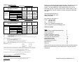
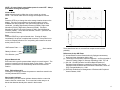
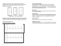
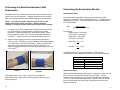
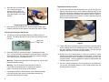
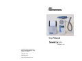
ABI
VASCULAR SYSTEM
User Manual
Listening to LifeTM
Summit Doppler Systems, Inc.
4680 Table Mountain Dr. #150
Golden, CO 80403
(303)423-7572
(800)554-5090
www.SummitDoppler.com
Warranty
Summit Doppler Systems, Inc. is pleased to present our customers with a 30-day
no hassle evaluation return policy in the event that you are not satisfied with our
product.
This product is warranted to be free from defects in materials and workmanship
for 12 months from the original sale of the device. This includes all parts and
labor required to repair or replace the unit to original specifications and shipping
costs associated with sending the product back to the customer. Customer is
responsible for providing adequate packaging materials and shipping costs to
Summit Doppler Systems. Products shall be repaired or replaced in a
reasonable amount of time.
Summit Doppler Systems’ liability for any claim is limited to materials and labor
associated with repair or replacement. In no event shall Summit Doppler
Systems be liable for incidental or consequential losses or damages in
connection with the purchase of this product.
Summit Doppler Systems disclaims all express or implied warranties,
agreements or arrangements other than issued in this warranty unless specified
in writing and signed by the President of Summit Doppler Systems.
Summit Doppler Systems is not responsible for damages to the device that occur
as a result of the inadequate shipping to Summit Doppler Systems, improper
maintenance or cleaning as described in the user manual, misuse, abuse,
alteration of the equipment from its original specifications, or dismantling the unit
(other than by Summit Doppler Systems approved service technicians).
Service Returns:
To return products to Summit Doppler 1. Call Summit Doppler Systems to obtain a Return Authorization and to receive
any final instructions prior to shipping.
2. Clean the product prior to shipping.
3. Ensure the device is well-packaged and suitable for shipment.
4. Include a note in the package with your contact information including Name,
Phone Number, and Return Address, as well as a description of the
problem.
Send the product to:
Service Department
Summit Doppler Systems, Inc.
4680 Table Mountain Dr. #150
Golden, CO 80403
For customer service, technical service, cleaning, maintenance or shipping
questions please call (303)423-7572 or 1-800-554-5090.
25
Application(s): Peripheral Vascular
Transducer Model: LifeDop 8 MHz Bi-Dir Operating Mode: Continuous-Wave (cw)
ISPTA.3
ACOUSTIC OUTPUT
Global Maximum Value
Pr.3
wo
fo
Associated
Acoustic
Parameter
zsp
MI
(Mpa)
(mW)
(MHz)
(cm)
x-6 (cm)
Beam Dimensions
y-6 (cm)
Az (cm)
EBD
Ele. (cm)
0.05
0.12
5.50
0.85
ISPPA.3
(mW/cm2)
(W/cm2)
500
0.5
32.7
0.32.7
5.50
0.85
5.50
0.85
0.4
0.6
0.4
0.8
0.4
0.6
Application(s): Peripheral Vascular
Transducer Model: LifeDop 5 MHz Bi-Dir Operating Mode: Continuous-Wave (cw)
Application(s): Peripheral Vascular
ISPTA.3
ACOUSTIC OUTPUT
MI
obal Maximum Value
Associated
Acoustic
Parameter
Pr.3
wo
(Mpa)
(mW)
fo
zsp
(MHz)
(cm)
Beam Dimensions
x-6
y-6
(cm)
(cm)
EBD
Az (cm)
Ele. (cm)
0.04
0.116
8.43
0.63
ISPPA.3
(mW/cm2)
(W/cm2)
365
0.37
15.7
15.7
8.43
0.63
0.42
0.14
0.6
0.3
8.43
0.63
0.42
0.14
ISPTA.3
the derated spatial-peak temporal-average intensity (mwatts per cm2).
the derated spatial-peak pulse-average intensity (watts per cm2).
ISPPA.3
MI
the Mechanical Index.
the peak rarefactional pressure (megapascals) associated with the transmit pattern giving rise to the
Pr.3
value reported for MI.
the total time-average ultrasonic power (mwatts).
Wo
the probe center frequency (MHz).
fc
zsp
the axial distance at which the reported parameter is measured (cm).
are the –6dB beam dim. in the x-y plane where zsp is found (cm).
x-6, y-6
EBD
the entrance beam dimensions (cm). These dimensions are the same as the dimensions of the
transmit crystal.
Measurement Uncertainties:
Power:
+34, -42%
Pressure:
+11, -16%
Intensity (Ispta):
+23, -26%
Frequency:
+/- 5%
Acoustic Output Parameters are measured in water. Derated values, denoted by the subscript “.3”, take into
account a conservative level of attenuation that would be encountered in the human body. The derated intensity
values (I.3) are obtained from water values of intensity (Iw) at a depth of z calculated by:
I.3 = exp(-0.23*0.3*f*z)*Iw
(where f is the probe frequency in MHz and z is the depth in centimeters)
Thank you for choosing Summit Doppler Systems. We believe you have
purchased the finest handheld Doppler and portable printer on the
market. Your total satisfaction is our highest priority as we strive to
continually improve our products and services. Please contact us with
any suggestions. We look forward to enjoying a long-term relationship
with you!
Summit Doppler Systems, Inc.
4680 Table Mountain Dr. #150
Golden, CO 80403
Here’s how you can reach us…
Phone: 1-800-554-5090
(303) 423-7572
Fax:
(303) 940-7165
e-mail us at: [email protected]
Visit our website at: www.summitdoppler.com
Table of Contents:
Page
Intended Use/Contraindications/Warnings……
Safety of Ultrasound…………………………….
Product Description……………………………..
Installation and Basic Operation………………..
Controls, Indicators & Connectors …………….
Performing the ABI Examination……………….
Interpreting the Exam……………………………
Maintenance/Cleaning…………………………..
Troubleshooting Problems………………………
Specifications…………………...………………..
Warranty…………………………………………..
2
3
5
6
7
10
15
18
21
23
25
Please read the manual carefully and become familiar with the operation,
features and maintenance of your Doppler prior to using the device or
accessories.
The derated peak rarefactional pressure is calculated from the value of measure water (pr) by:
Pr.3 = exp(-0.115*0.3*f*z)*pr
(where pressure is given in megapascals)
Additional Output Reporting Information for IEC 61157
8 MHz: Iob < 112 mW/cm2
Note that parameter Zsp in the probe reporting tables is the same parameter as Ip in IEC 61157.
Operating Conditions: There are no user controls which affect the ultrasound output.
24
Manual Part Number: MAN0026 Rev A
1
Summit Doppler Systems, Inc. provides general reimbursement
information related to the diagnosis of peripheral arterial disease as an
overview for our customers. It is important to understand that
reimbursement is a complex process and requirements are subject to
change without notice. It is the responsibility of the healthcare provider to
determine and submit appropriate codes, charges, and modifiers for
services that are rendered. Prior to filing any claims, customers are
advised to contact their third-party payers for specific coverage, coding
and payment information. Summit Doppler Systems, Inc. makes no
promise or guarantee of reimbursement by Medicare or any other
third-party payer.
Intended Use
This product will be used to detect blood flow in veins and arteries for
assisting in the detection of peripheral vascular disease.
Federal law restricts this device to sale by or on the order of a licensed
practitioner.
Contraindications
Warning: The vascular probes are not for fetal use.
Warning: The ultrasound probes are not to be used on or near the eyes.
Specifications
Degree of protection against electric shock:
Type B Applied part
Class II Equipment
Degree of protection against ingress of water:
IPX4 – extending 2.5 cm from tip
IPX1 – entire probe 2.5 cm from tip, excluding connector
Designed and tested to meet:
IEC601-1, IEC60601-1-2, IEC60601-1-4, IEC60601-2-37, EN5011-A
Connect the LifeDop only to equipment that meets the appropriate standards.
Dimensions (h w l):
Weight:
LifeDop
147x70x35 mm
320 grams
Printer
136x84x43 mm
280 grams
Operating temperature:
10 to 30 C
0 to 30 C
Operating humidity:
30 to 75 %
20 to 85 %
Transport/Storage temp:
–20 to 50 C
–20 to 60 C
Transport/Storage humidity:
5 to 90%, non-condensing for both units
(beyond 30 days, battery to be stored between –20 and 30 C)
Battery life
AA Alkaline 1.5V x3
LifeDop
40, 12-minute exams
Lithium Ion 3.7V
Printer
500 prints
Audio bandwidth and power:
245 Hz – 4 KHz, 0.33 W
Printer Paper Type/Size (max):
Printer Speed:
Printer Resolution:
Printer Impact Resistance:
Printer Communication:
Printer Recharger:
Thermal, 58mm wide, 33mm diameter
35mm/sec, 8 sec for standard printout
48mm wide, 8 dots/mm, 384 dots/line
1.5 meter on linoleum floor
RS232, 115.2K, 8/1, no parity
Input – 100-120VAC, 29VA, 50/60Hz
Output – 5VDC, 2.3A, center positive
Waveform Frequency Scale
Waveform Time Scale
Printout Length
Auto scaled to 4KHz, 2KHz and 1KHz
25mm/sec, 100 mm w/ 4 sec of data
38 mm total with header
Warning: The device is for use only on intact skin.
Warning: This device is not intended for use with HF surgical
equipment.
General Warnings
Warning: The LifeDop 300ABI is for use by qualified personnel only.
Read the User Manual before use.
Warning: Carefully route all cables and tubing to reduce the possibility
of patient entanglement or strangulation.
Warning: Do not plug any part of this device into a telephone or
modem.
Attention: Consult Accompanying Documents
Warning: Do not use equipment that is damaged or malfunctioning.
Seek appropriate service when needed. Inspect equipment regularly for
signs of damage. Use alternate equipment if needed.
2
Additional technical information is available upon customer request.
23
Printer LED Red or Orange
Green
LED
Flash 2x
Orange
LED
Red
LED
Flash
Flash 1x
Flash 2x
Flash 3x
Flash 4x
Warning: Do not connect Luer fittings from Summit Doppler equipment
into any other equipment.
Error
Solution
No Error
Low Battery
Out of Paper
Open Cover
Thermal Failure
Voltage Failure
Normal
Recharge
Reload Paper
Close Cover
Call Summit
Call Summit
Printer Not Printing (Error 9)
The LifeDop and printer have lost communication. This may be due to a
printer jam, paper empty, low printer battery or any of the above printer
error codes. To clear the error, lift the paper cover lever, reseat the
paper roll and close the cover. If printer communication is reestablished, the LifeDop will automatically print the buffered waveform. If
Error 9 persists, turn off both printer and LifeDop and re-start waveform
buffer.
Faint Signal is Audible, but Waveform is not Visible on Printout
The LifeDop main unit is designed to reject noise and certain artifacts.
Even a valid signal must reach a threshold before it can be printed;
therefore it is normal for some very weak signals to be rejected.
Verification of Printer Switch Setttings
Caution: Printer DIP switches are preset at the factory. The printer will
not function properly if they are moved from these set position.
The printer switches have been preset at the factory to the proper
location, however if they have been changed the printer will not function.
Orient the printer and set the DIP switches to match the following:
1 – Up
2 – Down
3 – Down
4 – Down
22
If there are questions or concerns regarding these warnings or
contraindications, please do not hesitate to contact Summit Doppler
Systems for further clarification.
In order to preserve, protect and improve the quality of the
environment, protect human health and utilize natural resources
prudently and rationally – do not dispose of waste electrical or
electronic equipment (WEEE) as unsorted municipal waste.
Contact local WEEE disposal sites or Summit Doppler Systems
to dispose of equipment.
Safety of Ultrasound
The Summit Doppler LifeDop 300 ABI System was designed with
physician and patient safety in mind. In early design phases, all potential
hazards were eliminated or reduced to As Low As Reasonably
Achievable (ALARA) by adhering to good design practices and industry
wide safety standards. Ultrasound procedures should be performed with
the ALARA principle in mind when delivering ultrasound energy into the
body.
The following official statements from the American Institute of
Ultrasound Medicine (AIUM) are provided for your general information
regarding the safe use of ultrasound.
Clinical Safety
Approved March 1997, October 1982
Diagnostic ultrasound has been in use since the late 1950s. Given its
known benefits and recognized efficacy for medical diagnosis, including
use during human pregnancy, the American Institute of Ultrasound in
Medicine herein addresses the clinical safety of such use:
There are no confirmed biological effects on patients or instrument
operators caused by exposures from present diagnostic ultrasound
instruments. Although the possibility exists that such biological effects
may be identified in the future, current data indicate that the benefits to
patients of the prudent use of diagnostic ultrasound outweigh the risks, if
any, that may be present.
3
Prudent Use
Approved May 1999
The AIUM advocates the responsible use of diagnostic ultrasound. The
AIUM strongly discourages the non-medical use of ultrasound for
psychosocial or entertainment purposes. The use of either twodimensional (2D) or three-dimensional (3D) ultrasound to only view the
fetus, obtain a picture of the fetus or determine the fetal gender without a
medical indication is inappropriate and contrary to responsible medical
practice. Although there are no confirmed biological effects on patients
caused by exposures from present diagnostic ultrasound instruments,
the possibility exists that such biological effects may be identified in the
future. Thus ultrasound should be used in a prudent manner to provide
medical benefit to the patient.
Safety in Training and Research
Approved March 1997, March 1983
Diagnostic ultrasound has been in use since the late 1950s. There are
no confirmed adverse biological effects on patients resulting from this
usage. Although no hazard has been identified that would preclude the
prudent and conservative use of diagnostic ultrasound in education and
research, experience from normal diagnostic practice may or may not be
relevant to extended exposure times and altered exposure conditions. It
is therefore considered appropriate to make the following
recommendation:
In those special situations in which examinations are to be carried out for
purposes other than direct medical benefit to the individual being
examined, the subject should be informed of the anticipated exposure
conditions, and of how these compare with conditions for normal
diagnostic practice.
Troubleshooting Problems
Warning: Use alternate equipment in case of unit failure. Call Summit
Doppler Systems Service Department if the probe or main unit
malfunctions.
Warning: Do not drop or mishandle the LifeDop, probes, aneroid or
other accessories. Damage to sensitive electrical components,
speakers, cables, transducers or plastic likely to occur.
Poor Sound Quality
•
•
•
•
•
•
•
Inadequate gel use
Try and relocate the probe for a better signal
Improper choice of probe frequency
Interference from other equipment
Probe coiled cable or battery contacts may be intermittent
Debris in the speaker may cause poor sound
Device damage from dropping the LifeDop, probes or accessories
Battery Indicator Flashing on LifeDop
Replace batteries as described above.
Radio Frequency Interference
The LifeDop was tested for immunity to electromagnetic interference at a
level of 3V/meter. Interference during normal operation may occur in the
presence of fields stronger than 3V/meter. If this occurs, try to increase
the distance between the LifeDop and the source of interference.
Contact Summit Doppler for more information.
Printer Self-Test
The printer will perform a self-test by turning the printer on while the feed
button is being held down. A checkered test pattern will print in addition
to the printer configuration and loaded fonts.
4
21
Recharging Printer Batteries
Product Description
Caution: Use only the battery and AC adapter supplied with the printer.
Use of any other battery and/or AC adapter is hazardous and may cause
damage to the equipment.
The LifeDop 300ABI is a full-featured handheld Doppler designed to
serve the needs of clinicians performing the ankle brachial index (ABI)
exam. Limb systolic pressures are obtained with a highly sensitive bidirectional ultrasound Doppler probe. Each limb pressure can be stored
for calculation of the left and right ABI’s. Doppler waveforms can be
stored for each ankle. Examination results are printed on a high-speed,
battery-powered, portable printer.
Warning: Do not connect the printer to the Doppler while the printer is
charging.
Turn the printer off. Lift the rubber flap
on the left side of the printer and plug in
the connector of the recharge adaptor.
Make sure recharger is plugged into a
standard 120VAC outlet. When properly
connected, the LED will be red. Upon
completion of charging the LED will turn
off. Remove the recharger and replace
the rubber flap.
Printer Recharger
The 8 MHz probe is optimal for measuring the systolic blood pressure in
the extremities for most patients. For larger patients, an optional 5 MHz
probe is available. The 5 MHz probe offers deeper penetration and a
slightly wider beam, but is actually less sensitive on shallow vessels than
the 8 MHz probe.
Accessories
Contact Summit Doppler Systems Service Department at:
1-800-554-5090 or (303)423-7572 to order by phone.
Description
Alkaline battery
Lithium Ion battery
Coiled Cable
Printer Cable
Carry Case
User Manual
Gel (60 gm)
Gel (250 gm)
Printer Paper (Labels)
Printer Paper (10 yr)
ABI Assessment Form
ABI In-Service Video
20
Main Unit and Doppler Probes
The L300ABI main unit is a handheld Doppler with keypad for calculation
of the ABI results. This battery powered unit is designed to provide the
best possible detection of arterial blood flow. The L300ABI uses bidirectional probes with 8 MHz (standard) or 5 MHz (optional) operating
frequency. Bi-directionality is the ability to discriminate arterial flow
towards and away from the probe, which is essential for proper display of
the ankle waveforms.
Part Number
BAT0002
BAT0006
CBL0001
CBL0030
PKG0006
MAN0026
GEL0001
GEL0002
MMH0014
MMH0015
MKT0180
MKT0076
The L300ABI is powered by three AA alkaline batteries and is provided
with a user-replaceable probe cable.
Probe
Catalog #
SD8B
SD5B
Description
8MHz Bi-Dir
5MHz Bi-Dir
ABI
X
X
Shallow
X
Deep
X
Portable Companion Printer
Exam results are printed on a high-speed battery powered printer. This
printer uses thermally sensitive paper. Our standard paper is adhesivebacked label paper. Label paper makes 8.5 x 11 inch report generation
fast and easy. The printer is powered by a lithium-ion rechargeable
battery and comes with its own recharger.
5
Installation and Basic Operation
Preparing the Equipment for Use
Recharge the printer before use. Plug the probe cable into the main
unit, and become familiar with the equipment’s capabilities and
limitations by reading the LifeDop and Printer User Manuals prior to use.
Connecting the Printer
Ensure that the printer is loaded with paper and connect the cable to the
LifeDop and printer as shown, with connector tabs down as labeled
“THIS SIDE UP”. Turn the printer on by HOLDING the power button
down (approximately 3 seconds) until the LED comes on. If the printer
is functioning properly and ready to print, the LED will flash green twice
every second.
Periodically (at least annually):
Inspect the main unit and probes for signs of cracks or breaks in the
mechanical housing. Inspect cables and connectors for signs of wear or
failure. The user should discontinue use of the unit with any sign of loss
of housing integrity. Contact Summit Doppler Systems for service at
800-545-5090 (USA) or 303-423-7572 (Outside of USA).
It is recommended that the printer’s rechargeable batteries be replaced
annually.
Replacing LifeDop Batteries
Caution: Replace batteries only with batteries supplied by Summit
Doppler Systems. The battery compartment only accepts AA size
batteries. See accessories list for part number and re-order information.
Caution: Be sure to follow any local, state and/or national requirements
when disposing of used batteries.
Open the battery compartment by depressing the tab and pulling outward
on the battery door. Remove the existing drained batteries by pushing
on the end of the battery that compresses the battery contact spring and
lift upwards. It is acceptable to use a small tool or pen to assist in this
step.
Printer Connections
To disconnect the printer cable from the LifeDop, press the tabs on the
edges of the connector. On the printer end, the latching tab is on the
back of the connector.
Caution: Forcing the cable upside down will cause damage to the
connector pins on the LifeDop, cable and printer. Note the label “THIS
SIDE UP”.
Note: When turning the printer on or off, it is important to remember to
hold the button down, approximately 3 seconds, before the printer will
respond.
6
Replace the batteries by paying close
attention to the polarity indicators on the
battery and the polarity indicators on the
battery holder in the compartment.
Positive (+) aligns with positive (button)
and negative (-) aligns with negative
(spring). Insert the battery such that the
spring contacts are loaded first and then
press the battery firmly into place.
Warning: If the batteries have been inserted incorrectly, the unit
will not function but the LifeDop will not be damaged.
19
Maintenance and Cleaning
Warning: The LifeDop is not designed for liquid immersion. Do not soak
or drop the Doppler main unit or probes in liquids. Use only spray or
wipe cleaners and disinfectants.
Warning: The LifeDop is not designed for sterilization processes such as
autoclaving or gamma radiation.
Warning: The LifeDop is not intended to be used on open skin. If there
is evidence of open wound contamination, disinfect the probe before
using again as described below.
Caution: Using cleaning solutions other than those specified by Summit
Doppler may cause damage to the device.
The LifeDop Doppler requires very little maintenance. However, it is
important to continuing function of the unit and the health of the patients
that the unit is cleaned and examined regularly per the following
guideline:
After Every Examination:
Excess gel should be wiped off prior to docking the probe. Probes and
main unit should be cleaned with a damp warm water cloth or
presaturated isopropyl alcohol wipes or spray such as Transeptic® from
Parker Laboratories, Inc. In particular, pay close attention to clean the
seams along the plastic lines at the probe face but do not allow water or
spray to enter through the connectors or speaker grill.
To disinfect the unit, use commercially available spray or wipe
disinfectants registered with the EPA – such as Precise® QTB from
Caltech Industries, Inc. Follow the manufacturer’s instructions and wipe
unit until it is dry of solutions. Examiners should wash hands and
change gloves after every exam. Refer to local and hospital policies for
cleaning and disinfection policies.
Store unit in a clean area free from dust and debris. Follow temperature
and humidity guidelines as specified at the end of this manual.
Caution: If the unit is to be stored for longer than 90 days without use,
remove the batteries prior to storage.
Loading Paper
Caution: Install the paper roll in the printer so the external side (heat
sensitive side) of the rolled paper is against the print head (down).
Caution: Do not use printer paper other than the type specified and
supplied by Summit Doppler. Other paper types could result in damage
or degraded print quality and may void the warranty.
Controls, Indicators & Connectors
Probe Connector
Volume
Headphone Jack
On/Off
Printer Connector
Site
Store Waveform
Print
Numbers
Clear
On/Off Control
Turn the LifeDop 300ABI on by pressing the On/Off button. LCD
indicators show power status. The LifeDop automatically shuts itself off
after 5 minutes if it is not being used, or after 20 minutes if a limb
pressure or ankle waveform has been saved.
Turn the printer on by pressing and holding the On/Off button until the
green LED comes on (approximately 3 seconds). Printer automatically
shuts itself off after 30 minutes.
18
7
NOTE: All stored data is erased when power is turned OFF. Always
print before turning off the power.
Abnormal Ankle Waveforms - Monophasic
Volume Slider
Adjust the audio level by sliding the volume control up or down.
NOTE: The volume slider does not change the headphone volume.
Site
Press the SITE key to change the active storage location shown on the
display. Each key press advances the storage location one time.
Available sites are presented in the order that an ABI exam is often
conducted, including Right Brachial Pressure (R-BRA), Right Ankle
Waveform (R-WAV), Right Ankle Pressure (R-ANK), Left Ankle
Waveform (L-WAV), Left Ankle Pressure (L-ANK), and Left Brachial
Pressure (L-BRA). There also two ABI sites, L and R. (See also Site
Location Indicator below)
Print
Press the PRINT key to print all stored data. Printing will begin
immediately if the printer is enabled and connected. If the printer is not
on-line, the display will show “Prn” and printing will commence as soon
as the printer is on-line.
ABI/Pressure Data
Site Locations
Battery Indicator
Flow Direction
Keypad Numerals 0-9
Enter each limb’s systolic pressure data using the numeric keypad. The
pressure is stored in the site location shown on the display. Once the
pressure is entered the unit automatically advances to the next site
location.
Clear (Below Numeral 0)
Pressing the clear button erases the pressure or waveform stored in the
currently selected SITE location.
These waveforms have no reverse flow component and minimal
pulsatility.
References for the ABI Exam:
[1] Human Blood Pressure Determination by Sphygmomanometery:
American Heart Association (AHA), 2001
[2] Techniques in Noninvasive Vascular Diagnosis – an Encyclopedia of
Vascular Testing; Daigle RJ, Summer Publishing, 2002: 137-148
[3] Olin JW. Clinical Evaluation and Office-Based Detection of
Peripheral Arterial Disease, contained in Primary Care Series:
Peripheral Arterial Disease and Intermittent Claudication; Hirsch AT
(Ed), Excerpta Medica, Inc., 2001
[4] ACC/AHA Guidelines for Management of Patients with Peripheral
Arterial Disease, 2005.
Site Location Indicator
When flashing, the site location indicator denotes that the current site
location does not contain data. The current site location stays on to
denote that data has already been stored in that location.
8
17
The Doppler waveforms are automatically scaled to a maximum
frequency of either 1 KHz, 2 KHz or 4 KHz for optimal waveform height.
Markings on the vertical axis are provided every 1 KHz. Printer
calibration is not required.
Flow Direction Bar Graphs
The flow direction bar graph provides a visual aid for acquiring the
Doppler waveform. The number of segments that are displayed is
proportional to the velocity of the blood flow. The arrows pointing to the
left indicate flow going toward the probe tip. The arrows pointing to the
right indicate flow going away from the tip.
Battery Icon
When flashing, the battery icon indicates that the LifeDop’s batteries are
low and should be replaced.
Auto-Scaling – 1 kHz, 2 kHz and 4 kHz
Blood flow in the direction toward the probe is shown above the baseline.
Flow away from the probe is shown below the baseline. Two traces are
provided so that flow in both directions can be displayed simultaneously.
Sample Doppler Waveforms
Normal Ankle Waveforms – Triphasic
Store Waveform
Press the red button on the side of the LifeDop 300ABI to store Doppler
waveforms in either the Left Ankle (L-ANK) or Right Ankle (R-ANK) site
locations. The display will show “Str” to indicated that an ANK site
contains stored data.
Probe Connector
Plug the probe cable into the top connector on the side panel.
Headphone Connector
Connect headphone (32 ohm) . Flow coming toward the probe is heard
in the left side, flow going away from the probe is heard in the right side.
The waveforms are pulsatile with forward and reverse flow.
16
9
Performing the Ankle Brachial Index (ABI)
Examination
The ABI for each leg is determined by dividing the ankle pressure by the
higher of the two arm pressures. Doppler waveforms from the ankles
aid in the diagnosis of PAD and are usually required for reimbursement.
NOTE: To avoid losing data during the exam, do not turn the
LifeDop off until the results are printed. Replace batteries
(LifeDop) or recharge (Printer) before beginning the exam if needed.
1. In a warm room, have the patient take off shoes and socks and rest
in a supine position for approximately 5 minutes prior to taking
pressures. Patient should wear thin, loose fitting clothing. Avoid
rolling up sleeves or pant cuffs in such a manner that it obstructs
blood flow [1]. Bulky items such as sweaters should be removed.
2. Wrap the cuffs snuggly around the arms and ankles as shown in
Figures 1 and 2. The edge of the cuff should be placed approximately
1 to 2 inches above the site of examination. Select the proper cuff
width, equivalent to 40% of the patient’s limb circumference. In
general, average sized adults use 10 cm cuffs, while larger adults use
12 cm cuffs [1].
Interpreting the Examination Results
Ankle Brachial Index
The ankle-brachial index (ABI) is determined by dividing the ankle
pressure by the higher of the two brachial pressures. A separate ABI is
determined for each leg. These calculations are done automatically by
the LifeDop 300ABI.
ABI =
ankle pressure
higher brachial pressure
For example:
Right brachial – 120 mmHg
Left brachial – 126 mmHg
Right ankle – 145 mmHg
Left ankle – 92 mmHg
Right ABI = 145 = 1.15
126
Left ABI = 92 = 0.73
126
An ABI less than 0.9 is considered abnormal. The following
interpretation levels are based on the 2005 AHA/ACC PAD Guidelines:
ABI Interpretation levels
> 1.3
Noncompressible
1.00 – 1.29 Normal
0.91 – 0.99 Borderline
0.41 – 0.90 Mild-to-moderate PAD
0.00 – 0.40 Severe PAD
Figure 1
Figure 2
While applying the cuffs, it may be a good time to explain the
examination to the patient and answer any questions they may have
during this period.
10
Doppler Waveforms
Waveforms are interpreted by examining the combination of rise time, fall
time, presence of reverse flow components, and height. Normal
waveforms have relatively fast rise- and fall-times and are multiphasic
(i.e one or more reverse flow components). With PAD the rise- and falltimes are lengthened, the reverse flow components are lost, and the
height is diminished.
15
Right Brachial Artery Pressure
3.
Move the hose to the left ankle
cuff. Take the left ankle
pressure from the DP or PT
and enter the systolic pressure
using the keypad in the L-ANK
location.
8. Connect the hose from the hand pump to the cuff on the right arm.
Apply a small amount of gel over the patient’s brachial artery on the
right arm and place the Doppler probe at approximately 45 degrees,
pointing in the direction toward the shoulder as shown in Figure 3.
Slide the probe laterally across the arm to find the brachial artery and
obtain the best signal possible.
Determining the Pressure at the Left PT
4. Move the hose to the left arm cuff. With the Doppler probe on the
brachial, obtain the left arm pressure and enter this value at L-BRA.
Viewing and Printing the ABI Results
5. The ABI for the left leg is displayed after the L-BRA pressure is
entered. The ABI for the right leg can be seen by pressing the SITE
key once.
ABI for the
Right Side
Figure 3
9. Find a stable and comfortable position to brace the probe hand while
quickly inflating the cuff 20 mmHg above the occlusion pressure, at
this point Doppler sounds are no longer heard. Be sure that the
Doppler probe stays on the artery during inflation [2].
6. Press the PRINT key to print the results. The display will show
“Prn”. Printing will begin immediately if the printer cable is connected
and the printer is on. Otherwise the LifeDop will continue to display
“Prn” until the printer is connected and on.
Warning: The print head becomes hot during printing. Do not touch
the print head after printing.
Warning: Turn off the printer and check that the head is
fully cooled before attempting to fix a paper jam, replacing
paper, or removing the print roller for any reason.
10. Deflate the cuff at approximately 2 mmHg per second by gently
squeezing the pressure release trigger on the aneroid. Listen for the
blood flow sounds to return. When the flow sounds return, this is the
systolic pressure. Once this pressure is obtained, rapidly deflate the
remaining pressure in the cuff [2].
11. Use the LifeDop’s keypad to enter the pressure for the R-BRA site.
The site will automatically advance to the R-ANK location after the
brachial pressure is stored.
7. Cut the printed data into three sections at the indicated markings.
Peel the back from each section of label paper and stick the
pressures and two waveform strips.
14
11
Right Ankle Waveform
Right Ankle Pressure
12. Acquire a Doppler signal at either the posterior tibial (PT) or dorsalis
pedis (DP) artery as shown below. Start by applying a small amount
of gel to the site and tilt the probe at a 45 degree angle, pointing the
probe tip toward the calf and knee. Slide the probe across the
general location of the artery until the best signal is obtained.
Normal patients will usually have tri-phasic or bi-phasic ankle
waveforms. Patients with peripheral arterial disease (PAD) will have
reduced flow which results in a waveform with fewer changes in flow
direction. Often with these patients the signal will be mono-phasic,
meaning the flow is always in one direction.
14. Connect the cuff hose to the right ankle cuff. Use either the PT or
DP artery to obtain the ankle systolic pressure. Acquire the Doppler
signal. Brace your probe hand while inflating the cuff to a pressure
20 mmHg above the occlusion pressure, which is the point at which
flow sounds are no longer heard. Be sure to keep the probe on the
artery while inflating.
15. Deflate the cuff at 2 mmHg/sec by gently squeezing the pressure
release trigger on the aneroid. Be sure not to move the probe.
Listen for the blood flow sounds to return – this is the systolic
pressure. Note the pressure when flow returns, then rapidly deflate
the cuff.
16. Use the LifeDop’s keypad to enter this pressure in the R-ANK site.
The site location will automatically advance to the L-WAV location.
NOTE: Some protocols call for obtaining pressures from both the DP
and PT arteries and using the higher of the two pressures in the
calculation of the ABI. In this case obtain both pressures and then
enter the higher of the two in the R-ANK location.
Right DP
Right PT
13. Maintain the best signal possible for a minimum of 4 seconds and
press the red button on the side of the LifeDop to store the waveform
in the R-WAV location. The site location will show “Str” and then
automatically advance to R-ANK.
Storing the Right Waveform
12
Completing the Exam for the Left Side
17. Obtain the Doppler waveform from the patient’s left ankle (DP or PT
artery) and use the red button to store in the L-WAV location.
Left PT
Left DP
13