1
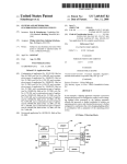
International Journal of Electrical, Electronics and Data Communication, ISSN (p): 2320-2084, Volume-1, Issue-1, March-2013 DEATH REDUCTION IN ACCIDENTS SYSTEMS USING EMBEDDED TOOL KIT IN Lab VIEW 1 C. SIVAPRAKASH, 2P. MUTHUKUMARAN Instrumentation and Control Engineering Electronics and Instrumentation Engineering Sairam engineering college, Chennai Email: [email protected], [email protected] Abstract—Each vehicle has a transponder - the RFID (active) tag which have its driver details, model, registration number etc., as the data to be transmitted. So each vehicle actual communicates with other vehicles. A proximity sensor is placed in front of the vehicle so the distance of nearness is found this is given as input to a LPC 2148 .It is connected to a pneumatic brake system. The LPC 2148 checks for the condition if the vehicle is at a safe distance from the nearest automobile no action is done or otherwise when distance between the two vehicles is below 3 meters for highway roads, 1-2 meters in traffic a alert is made to both the drivers .if intermediate distance decreases further LPC 2148 sends a signal which results in applying pneumatic brakes. In order to keep in check the formation of co gas formation in air conditioning a co sensor is installed at important places .This will also help us in detecting fire but to obtain a complete protection from fire we need a fire sensor. If the level of co increases more than 400ppm or the heat levels go to dangerous level brakes are applied. Surveillance of each vehicle is also possible in RFID technology that to in a minimal cost. Power needed is very low, maintenance needed is very less, can work in harsh environments. Keywords— LPC 2148, ARM 7 processor RFID, proximity sensor, stepper motor, LAB view embedded module I. tag antenna is generally physically integrated with the target, and society. In the section A we give a briefly introduction of RFID tracking with LPC 2148 and our idea of using in ARS systems .In section B overview of ARS system. In section C operation of the system with block diagram .Section D describes the algorithm of the program used in the accident reduction system (ARS).In section E the different areas of applications of this ARS INTRODUCTION India suffers from the highest number of deaths - around 1,05,000 in absolute terms annuallydue to road accidents .Some mistakes occur when a driver becomes distracted, perhaps by a cell phone call, poor maintenance of vehicles, due to fire accidents etc., Use of this technique in public or in private transport systems enhances the safety and thereby reducing the loss of both human lives and the property of humans. LPC 2148 is used to control the integral parts of the systems.LPC 2148 has a 32 bit ARM7TDMI-S CPU. The ARM7TDMI-S is based on RISC principles.I2C connection (i.e.) Inter-Integrated Circuit Communications can be use which allows a master device to initiate communication with slave device.I2C protocol defines the master device as that is in charge of bus at the present time and this device controls the clock and generate START and STOP signals .Slave simply listen to the bus and act on controls and data that they are sent. They do not transfer data between themselves. Data is exchanged between devices and it is synchronous protocol. It uses VPB (VLSI peripheral bus), Fast general purpose I/O and General purpose I/O as FGPIO is 3.5 times faster than GPIO.Although the basic concepts of radiofrequency identification (RFID) were developed during World War II, only recently has RFID become a ubiquitous technology in today’s industry, mark An archetypal RFID system consists of an interrogator, more often known as a reader, a transponder or tag, and antennas to mediate between voltages on wires and waves in air. The reader antenna or antennas may be integrated with the reader or physically separate and connected with a cable; the II. INTRODUCTION TO RFID TRACKING WITH LPC 2148 AND OUR IDEA OF USING IN ARS SYSTEMS RFID tracking starts with identification of tags of other RFID transponders. Here we use active type RFID working in HF and UHF range. Each RFIDS can communicate with other RFIDS in that location. RFID has a tag which have a driver details, model, registration number etc., Every RFID have many such RFIDS in its region of communication. RFIDS have a variety of frequencies scanning over the range of frequencies makes us to find the number of vehicles in an area of scope and its corresponding details. We make in use information and use it for reducing accidents, surveillance and tracking of missing vehicles on ground itself over a particular region with good accuracy It overcomes the disadvantages of GPS systems such as weight and cost .LPC 2148 is interfaced with RFID as LPC 2148 has many peripherals built within it so no external devices are to be interfaced and so does the power supply given to it. Death Reduction in Accidents Systems Using Embedded Tool Kit In Lab View 24 International Journal of Electrical, Electronics and Data Communication, ISSN (p): 2320-2084, B.OVERVIEW OF ARS SYSTEMS III. INTERFACING OF SENSORS the interrogator has to be further modulated with the specific code; otherwise, the interrogator will only transmit the radiofrequency carrier. In either case, the radiofrequency signal is then amplified to specific power levels and passed through the tuning a circuits before reaching the antenna. The antenna is also used to detect the backscatter signal generated by the transponder, which, after being filtered, is then amplified and demodulated if necessary. Antennas for interrogators operating in the HF ranges are designed for parameters such as maximum read distance for transponders, transponder read rate, as well as regulations such as the maximum field allowed in some specific conditions. The sensors used in ARS systems are Fire or smoke and proximity sensors. A smoke and fire detector is a device that detects smoke, typically as an indicator of fire. Commercial, industrial, and mass residential devices issue a signal to a fire alarm system, while household detectors, known as smoke alarms, generally issue a local audible and/or visual alarm from the detector itself. Smoke detectors are typically housed in a disk-shaped plastic enclosure about 150 millimetres (6 in) in diameter and 25 millimetres (1 in) thick, but the shape can vary by manufacturer or product line. Most smoke detectors work either by optical detection (photoelectric) or by physical process (ionization), optical type is used here because the source can be used as a source for illumination of the space in vehicle and for detection purpose. A solenoid valve is connected to the opening of the fire extinguisher so that the control of the material to suppress the fire depends on the position of solenoid valve .The co levels is also monitored. If the levels go higher than 400ppm which is dangerous to humans necessary actions are done with the help of ARM 7 processor A proximity sensor is a sensor able to detect the presence of nearby objects without any physical contact. A proximity sensor often emits an electromagnetic or a beam of electromagnetic radiation (laser), and looks for changes in the field or return signal. The object being sensed is often referred to as the proximity sensor's target. As the vehicles in now a days have most of it made of metal parts. Laser proximity sensor is used here which is over a 180 degree area up(SICK LMS-200). The operating distance is about 6000mm or 6 meters which is enough for this application. Added advantage is that above sensors can be interfaced with ARM processor with respective ADC0 and ADC1 which are burst mode A/D convertors. IV. Volume-1, Issue-1, March-2013 Forward and Reverse Link Budgets for Directional Antenna. Here the antennas for HF interrogators are based on a small dipole that generates an electric field. These antennas are normally called stick antennas. RFID is interfaced with ARM processor through USARTs both for transmission and receiving. The most important feature in USART is that standard modem interface signals included with flow control (auto-CTS/RTS) is supported in hardware and built in fractional baud rate generator with autobauding capabilities RFID RFID’s use transponder The two main components of a transponder are its internal circuits and its antenna. When the transponder is operating in the UHF region, the wavelength of the electromagnetic radiation is now comparable to the dimensions of the antenna. Because the antenna is no longer electrically small, a dipole can now be used. The half-wave dipole receives its name because its length equals half of the wavelength of the current signal traveling through the antenna. Interrogators have two basic functions: to generate and transmit the radiofrequency signal used to energize the transponders and to receive and decode the backscattered signal generated by the transponders. If the transponder is able to accept commands from the interrogator, the radiofrequency signal generated by V. STEPPER MOTOR Stepping motors can be viewed as electric motors without commutators. Stepper motors consist of a permanent magnet rotating shaft, called the rotor, and electromagnets on the stationary portion that surrounds the motor, called the stator. All of the commutation must be handled externally by the motor controller, and typically, the motors and controllers are designed so that the motor may be held in any fixed position as well as being rotated one way or the other. To move the rotor the electric Death Reduction in Accidents Systems Using Embedded Tool Kit In Lab View 25 International Journal of Electrical, Electronics and Data Communication, ISSN (p): 2320-2084, magnets on the motor are activated in the right order. Every change in this process moves the motor one step. The order in which those electromagnets are activated determines the rotation direction. The stepper's resolution is based on the steps (typically 1.8 deg or 3.6 deg per step). In the stepper system, the driver advances one step, and the stepper motor follows. For example a 1.8 deg. stepper will turn a full circle in 200 steps. No matter how you gear it, a stepper motor still moves in discrete steps. Each step covers a specific range of "swing". In a nutshell, a stepper (with or without gear-train) is a set of "preset" positions you can move to. Any position that's not part of the "presets" is unattainable by that motor or motor-and-gear-train combination, and can only be reached as an approximation. Stepping motors can be used in simple open-loop control systems; these are generally adequate for systems that operate at low accelerations with static loads, but closed loop control may be essential for high accelerations, particularly if they involve variable loads. If a stepper in an openloop control system is overtorqued, all knowledge of rotor position is lost and the system must be reinitialized.PWM in LPC 2148 can used for pulses generation. Stepping motors come in a wide range of angular resolution. The coarsest motors typically turn 90 degrees per step, while high resolution permanent magnet motors are commonly able to handle 1.8 or even 0.72 degrees per step. With an appropriate controller, most permanent magnet and hybrid motors can be run in half-steps, and some controllers can handle smaller fractional steps or micro steps. It is possible to achieve micro steps in the order of 10 increments between the native increments. With micro stepping their limitations: The divisions generally turn out to be less than totally linear. For example, with the two coils each half on, you are going to get a position that is just about half way between the two steps, but when you get more near to the ends of the positions, more non-linear the response becomes. There are lots of factors which affect the error, and most are related to the construction of the motor itself. Some of the top end (expensive) chopper controllers support 256 micro steps and even have error correction systems that are said to make 256 * 200 = 51,200 positions a reality. The stepper motor is used for opening the emergency windows VI. Volume-1, Issue-1, March-2013 to STEPPER MOTOR which gets the input from PWM ports. VII. EEPROM EEPROM (electrically erasable programmable read-only memory) is user-modifiable read-only memory (ROM) that can be erased and reprogrammed (written to) repeatedly through the application of higher than normal electrical voltage. Unlike EPROM chips, EEPROMs do not need to be removed from the computer to be modified. However, an EEPROM chip has to be erased and reprogrammed in its entirety, not selectively. It also has a limited life - that is, the number of times it can be reprogrammed is limited to tens or hundreds of thousands of times. In an EEPROM that is frequently reprogrammed while the computer is in use, the life of the EEPROM can be an important design consideration. Information like “help”, “danger” are stored here and are retrieved, transmitted through RFID. The serial data pin of serial EEPPROM IC24LC01B is connected to the sda1(po.14)of I2C bus of LPC 2148.Reading any number of bytes of data from selected EEPROM addresses require that a starting address first by sent to the EEPROM with message string . VIII. PROGRAMMING USING LABVIEW EMBEDDED MODULE NI Lab VIEW Embedded Module can be used to program any ARM processors. The module is the first product in an ongoing collaboration between the companies that combines the ease of use of Lab VIEW. The LabVIEW Embedded Module for ARM Microcontrollers features LabVIEW drivers that make it possible for domain experts to graphically program all components of the ARM microcontroller including the analog and digital I/O. The module also features desktop simulation capabilities so that users can run the programs they develop for an ARM microcontroller on a desktop PC without any additional hardware. With the performance of ARM microcontrollers. The number interactive computer delivered simulation, control, and scientific visualization software are available in the market, and many application-specific tools have already been reported in the literature, which use diverse software, such as Hypertext, Authorware, Director, Labtech, Visual C++, Visual Basic, Matlab/Simulink, and LabVIEW. It is found that the following criteria may be contemplated for selecting application software to build a virtual instrumentation that may be used in education. Modularity, allows to test individual modules easily and to develop applications quickly. CONTROL ACTION TAKING SYSTEMS Solenoid vales which surround the opening of fire extinguisher, pneumatic brakes locks that open the windows. The above connections are in I2C communication (Inter-Integrated communications)I2C is a synchronous protocol that allows a master device to initiate communication with slave device .The master device is LPC 2148 and the other devices are slave device. The windows of the bus are connected Death Reduction in Accidents Systems Using Embedded Tool Kit In Lab View 26 International Journal of Electrical, Electronics and Data Communication, ISSN (p): 2320-2084, Volume-1, Issue-1, March-2013 driver in that vicinity receives a message “HELP” with driver’s information such as name, vehicle’s registration number .Thus vehicles which receive the message have a chance of saving the live. Inside the vehicle, EEPROM alarm and pneumatic brakes are inI2C protocol, so the SDA and SCL signals are given. LPC 2148 I2C interfaces are byte oriented and have four operating modes master transmitter mode, master receiver mode, slave transmitter mode, slave receiver mode the former two modes are only used . The devices in I2C communication are Alarm, pneumatic brakes, EEPROM and solenoid valves. block diagram of ARS system The lab view software is used as for the following reasons. Adding warning/message sounds or voices, Providing instructions, pre-practical tutorials and/or interactive short-tests, Generating a test report or a data file in a common text format, Printing a specific chart or a part of the user front panel, Linking to other currently available systems and software, Including passwords to limit the access, Animating the system or sub-system operation for easy understanding, Providing GUI that mimics the real instruments. Normally LPC 2148 needs three softwares to program it .Thus using lab view embedded module the time of programming is lessened, with the less knowledge about the programming languages in LPC 2148 module, just knowing the knowledge of lab view. Front Panel Window simulation C.OPERATION OF ARS SYSTEMS The USART present in LPC 2148 is used for bit framing which allows the data to transmit through RFID. There two USARTs i.eUSART0&USART1 one can act as receiver and other for transmitting simultaneously. The PWM in LPC 2148 which gives the input to operate the motor is used to open Emergency windows so that the causalities may have a fair chance of survival and to allow Rescue teams to enter the vehicle. Solenoid valve in the opening of fire extinguisher this enables to have a control over fire D.ALGORITHM OF ARS SYSTEMS If (mode==traffic) { If (distance<1 meter) { Brake=1//brakes are applied// } Else if (distance<2 meters) { Alarm=1//Alarm rings & “DANGER” word is transmitted in RFID// } Else if (fire &smoke sensor==1) { Solenoid valve=1 //activate fire extinguisher // Brake=1//brakes are applied&“DANGER” word is transmitted in RFID // } } Else if (mode==highway) { If (distance<3 meter) { Brake=1//brakes are applied// } Else if (distance<1.5 meters) { Alarm=1//Alarm rings & “DANGER” word is transmitted in RFID// } Else if(fire &smoke sensor==1) { There are two types of control operations performed, one is to avoid accidents and other are the steps to be taken for mishaps inside the vehicles. On the outer side of this system are the proximity sensors fixed on the front, back and sides of the vehicle. In the inside of the vehicle is the safety sensors such as fire and smoke sensor are placed in prime positions of the vehicles. There are two scenarios when brakes have to be applied, one when two vehicles are in position of collision or when fire accidents occur or when levels of co gas are above 400ppm. ARM 7 processors has inputs for proximity sensors and fire / smoke sensors. The outputs are given to solenoid value, pneumatic brake systems window opening systems .when vehicles come about 3 meters in highways and 1-2 meters in traffics RFID sends a alarm signal with “danger” displaying in vehicle’s GUI say with LED display to both of the drivers with the information of each other’s, any distance nearer results in applying brakes in the car which receives less proximity signal. In case of internal calamity such as fire the vehicle is stopped and any vehicle in that vicinity will receive a message of help .This message transmitted to another vehicle and so on for five vehicles till the primary medical centre which has a tag reader on every 1 km receives the additional feature is that each Death Reduction in Accidents Systems Using Embedded Tool Kit In Lab View 27 International Journal of Electrical, Electronics and Data Communication, ISSN (p): 2320-2084, Solenoid valve=1 //activate fire extinguisher // Brake=1//brakes are applied&“DANGER” word is transmitted with RFID // } Volume-1, Issue-1, March-2013 GPIO lines with up to nine edge or level sensitive external interrupt pins make these microcontrollers suitable for industrial control and medical systems. No doubt using this module increases safety in vehicles. RFID technology does not require line-ofsight reading. Unlike a bar code, an RFID tag can be read through other materials (though some materials may cause problems). RFID tags can hold more data than bar codes. The operative word here is “can”. RFID tags are more effective in harsh environments where bar code labels have problems. RFID tags can be sealed within a plastic enclosure eliminating many of the problems that plague bar codes in harsh environments where they are exposed to chemicals, heat, abrasion, dirt, etc. A large number of RFID tags can be read almost instantaneously. This brings us back to the palletized load scenario where the load contains a large quantity of products, each with its own RFID tag. Though it may seem as though the tags are all read at once, they are actually read sequentially (one at a time), however, this happens so fast that it is virtually imperceptible.Thus for not only industrial uses RFID can be used in Tracking, surveillance and for many more uses. } E.APPLICATIONS OF ARS SYSTEMS This system is mainly used in all typed of four wheeled vehicles like trucks, cars etc .This reduces the speed in area near schools, hospitals and worship places to ensure safety of people . Tracking of vehicle is possible here in a local confinement thus everyone knows about everyone. There is a chance of helping other in times of mishaps or disaster this increases the social responsibility in people’s minds. REFERENCES [1] [2] [3] [4] [5] [6] [7] [8] [9] F.CONCLUSIONS [10] The progress in science & technology is a non-stop process. New things and new technology are being invented. As the technology grows day by day, we can imagine about the future in which thing we may occupy every place. Now a day’s several applications are done by help of the embedded system in many platforms. It acts as a major role in industry. The growth of the embedded system is very useful to Engineers. The upcoming projects are designed by the embedded. Embedded systems have more advantage than other system that’s why we are used embedded systems applications Due to their tiny size and low power consumption, LPC 2148 are ideal for applications where miniaturization is a key requirement, such as access control and point-of-sale. Serial communications interfaces ranging from a USB 2.0 Full-speed device, multiple UARTs, SPI, SSP to I2C-bus and on-chip SRAM of 8 kB up to 40 kb Various 32-bit timers, single or dual 10-bit ADC(s), 10-bit DAC, PWM channels and 45 fast [11] [12] [13] [14] Jerry Banks, RFID applied By Daniel Mark Dobki ,The RF in RFID: passive UHF RFID in practice Paris Kitsos, Yan Zhang, RFID security: techniques, protocols and system-on-chip design Dennis E. Brown RFID implementation Dirk Henrici,RFID security and privacy: concepts, protocols, and architectures George Miles, Imogen Clout, Clare Firth, Foundations for the LPC 2007-2008 Gereon Meyer, Jürgen Valldorf,Advanced Microsystems for Automotive Applications 2010 Natividad Martínez Madrid, Intelligent Technical Systems Vinu V. Das, Nessy Thankachan, Computational Intelligence and Information Technology. R. A. Sherry and S. M. Lord "LabVIEW as an effective enhancement to an optoelectronic laboratory experiment", Proc. Frontier Educ. Conf., pp.897 -900 1997 M. Santori "An Instrument that Isn\'t Really (Laboratory Virtual Instrument Engineering Workbench)", IEEE Spectrum, vol. 27, no. 8, pp.36 -39 1990 H. J. W. Spoelder "Virtual Instrumentation and Virtual Environments", IEEE Instrumentation & Measurement Magazine, vol. 2, no. 3, pp.14 -19 1999 L. Cristaldi , A. Ferrero and V. Piuri "Programmable instruments, virtual instruments, and distributed measurement systems: what is really useful, innovative and technically sound?", IEEE Instrumentation & Measurement Magazine, vol. 2, no. 3, pp.20 -27 1999 LabVIEW User Manual, 1996 Death Reduction in Accidents Systems Using Embedded Tool Kit In Lab View 28