1
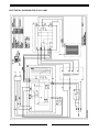
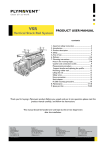
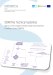
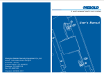
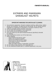
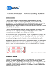
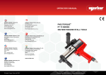
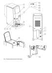
CAM Clean air module
EN
User manual
www.plymovent.com
PREFACE
TECHNICAL SPECIFICATIONS
Using this manual
The specifications given in this publication do not
include normal manufacturing tolerances. Therefore,
this unit may not exactly match the listed
specifications. This product is tested and calibrated
under closely controlled conditions, and some minor
differences in performance can be expected if those
conditions are changed.
This manual is intended to be used as a work of
reference for users to be able to safely use the clean air
module CAM.
Pictograms and symbols
The following pictograms and symbols are used on the
product and in this manual.
WARNING
Procedures, if not carried out with the
necessary caution may damage the product
or cause personal injury.
ATTENTION
Procedures, if not carried out with the
necessary caution, could damage the
product or the environment.
Technical specifications
Dimensions H x W x D
620 x 360 x 210 mm
Power consumption
25 W
Max. capacity
1500 m3/h
Collector surface
2,35 m2
Weight
13 kg
Power supply
230 V, 50 Hz
Filter efficiency
>80%
Main filter
electrostatic
Housing
epoxy-coated steel
Pressure drop
< 150 Pa
INTRODUCTION
Ambient conditions
Identification of the product
Min. operating temperature
5°C
Max. operating temperature
45°C
Max. relative humidity
75%
The identification plate contains the following data:
•
•
•
•
serial number
product name
power consumption
supply voltage and frequency
FEATURES
•
•
•
•
Solid state power supply is self-regulating and
maintains peak efficiency during a wide range of
cell dirt loading conditions.
Electronic cell(s) can be washed in most
dishwashers.
Galvanized/Epoxy coated cabinet (exterior +
interior) protects against rust.
Prefilter screens(s) protects cell(s) from large dirt
particles.
GENERAL DESCRIPTION
The high efficiency clean air module CAM air cleaner is
mounted in the return air duct of a forced air heating,
cooling, or ventilation system. It captures a significant
amount of airborne particles 0.5 microns and larger
from the air circulated through it. All models have an
internal air flow switch to operate the CAM when the
system blower is on.
Note: The specifications given in this manual
must not be altered.
SAFETY INSTRUCTIONS AND
WARNINGS
General
The manufacturer does not accept any liability for
damage to the product or personal injury caused by
non-observance of the safety instructions in this
manual.
Specific working conditions may require additional
safety instructions. Immediately contact your supplier
if you detect a potential danger when using the
product.
The user of the product is always fully
responsible for observing the local safety
instructions and regulations. Observe all
applicable safety instructions and regulations.
User manual
•
•
•
0507430060/010111/A
Everyone working with the product, must be
familiar with the contents of this manual and must
strictly observe the instructions therein. The
management should instruct the personnel in
accordance with the manual and observe all
instructions and directions given.
Never change the order of steps to perform.
Always keep the manual with the product.
EN - 2
Safety features
•
•
•
All safety features must be correctly mounted and
can only be removed for maintenance and repair
jobs by skilled and authorised service engineers.
The product must not be used if the safety features
are not or only partly present, or defective.
The safety features should be regularly checked for
their proper functioning, and if required, be
immediately repaired.
Modifications
•
Modification of (parts of) the product is not
allowed.
POSITIONING ELECTROSTATIC FILTER
Installation
•
•
•
•
•
•
Inspect the product and check it for damage. Verify
the functioning of the safety features.
Check the working environment. Do not allow
unauthorised persons to enter the working
environment.
The product is not explosion-proof rated. It can
cause sparks and should therefore not be used in
areas with an explosion risk.
Never operate the product without filters.
If the air cleaners is installed close to an elbow or
angle fitting, install turning vanes inside the angle
to distribute airflow more evenly across the face of
the air cleaner.
Transitions are needed when the duct is a different
size than the air cleaner cabinet. Gradual transitions
reduce air turbulence and increase efficiency.
Note: Change duct size gradually to minimize
turbulence.
OZONE AND THE ELECTRONIC AIR
CLEANER
The electronic air cleaner generates a small amount of
ozone in normal operation. During the first week or two
of operation the amount may be higher because of
sharp edges on some of the new high voltage metal
parts. Normal use dulls these edges in a short time.
OUTDOOR AIR INTAKE APPLICATIONS
Return air temperature must be at least 15°C.
Lower temperatures can cause ionizer wire
failure. If outdoor air is used, warm it upstream
from the air cleaner by:
•
Making sure the outdoor intake is far enough
upstream from the air cleaner so the return and
0507430060/010111/A
•
•
outdoor air is thoroughly mixed. Stratified air can
dump a stream of very cold air into one section of
the air cleaner.
Adding baffles upstream from the air cleaner to
force thorough air mixing.
Installing a preheater, which could be an electric
strip heater or hot water coil, to be controlled by a
thermostat. Hot water or steam coils should be
protected by a freeze-up control.
Service, maintenance and repairs
•
•
•
•
•
Always use tools, parts, materials, lubricants and
service techniques that have been approved by the
manufacturer. Never use worn tools and ensure
that tools are not left behind in or on the product.
Do not carry out any maintenance on the product
before it has been protected against unintended
starting.
Safety features removed for maintenance shall be
re-installed immediately and checked for proper
functioning.
Regularly clean the inside of the housing.
Clean or replace the filters in time.
GENERAL DESCRIPTION
The CAM clean air module consists of the following
main components (see fig. 1 on page 6):
• electrostatic filter (ElectroMax) (8)
• electromodule (5)
The extracted contaminated air passes the pre filter
(fig. 7a) that takes out all larger particles. The pre filter
also ensures a proper distribution of the airflow. After
that, the air passes the ElectroMax filter (8). The
contaminations in the air are electrically charged by the
high voltage (+8kV). These will then be deposited on
the collector plates of the ElectroMax filter. The final
filter (7b) is the last filtration step which also spreads
the airflow.
There are a main switch (6) and an indicator LED (3) on
the front panel. Please contact your dealer if the
indicator LED is not working.
OPERATION
Large particles (e.g. lint, hair, dust) are caught by the
prefilter. As the dirty air passes through the intense
high voltage electric field surrounding the ionizer wires,
all particles are given an electrical charge. The air then
moves through the collector part of the cell where
alternate parallel plates are charged positively and
negatively, creating a uniform electrostatic field. The
charged particles are attracted to and collect on the
plates having the opposite electrical charge. The air
leaving the air cleaner has fewer particles. Each time
the air circulates through the CAM, more particles are
removed.
EN - 3
CLEANING THE ELECTROSTATIC
CELL(S) AND PREFILTER(S)
To assure optimum performance from the air cleaner,
the cell(s) and prefilter(s) must be cleaned regularly;
every one to six months. Washing frequency will vary
depending on the use.
Note: Vacuum the prefilter or brush, or soak it in
a tub. Do not wash the prefilter in the dishwasher
or car wash.
Use the EFC detergent for cleaning (available on
request).
WASHING THE CELLS IN A CONTAINER
•
•
Do not splash the detergent solution in eyes. Wear
rubber gloves to avoid prolonged detergent contact
with skin.
Keep detergent and solution out of reach of
children.
Note:
•
•
Always wash the cell(s) first, then the prefilter, to
keep heavy prefilter lint from getting caught in the
cell(s).
Use a large enough container, such as a trash
container, to hold one or both cell(s).
Housing:
• Remove the front panel (4).
• Remove the prefilter (7a), the ElectroMax filter (6)
and the final filter (7b).
• Unscrew the electromodule (5) and remove it.
• Unscrew the reinforced rail that is mounted at the
right bottom side.
• Turn the reinforced rail 180° horizontally and
mount it the same way at the left bottom side.
Electromodule:
• Remove the filter guide rails from the electromodule
(5).
• Remove the red contact plate (1) by sliding.
• Turn the red contact plate (1) 180° horizontally and
replace it.
• Mount the filter guide rails to the electromodule (5).
• Replace the electromodule (5) and mount it.
Housing:
• Insert the prefilter (7a), the ElectroMax filter (6) and
the final filter (7b).
• Replace the front panel (4).
TROUBLESHOOTING
If the machine does not function (correctly), consult
the checklist below to see if you may remedy the error
yourself. Should this not be possible consult a qualified
service engineer.
CHANGE OF AIRFLOW DIRECTION
The standard airflow of the clean air module is from left
to right. If desired, the airflow direction can be changed
from right to left. Proceed as follows (see fig. 1 on
page 6):
ATTENTION
Disconnect the CAM from the mains.
Signal
Problem
Dust or other particles No power on the
from the final filter
ElectroMax filter.
and/or blinking
indicator LED.
WARNING
First check whether the error is of a
mechanical or electrical nature. The electric
system can only be serviced or repaired by
qualified and authorised service engineers.
ATTENTION
Always switch OFF the clean air module and
disconnect the mains before carrying out any
repairs. First read the repair instructions at
the beginning of this manual.
Possible cause
Solution
Short-circuit in the ElectroMax
filter (caused by particles).
Clean or replace ElectroMax
filter.
Short-circuit in the ElectroMax
filter (caused by bent lamellas).
Check and repair or replace.
High voltage transformer
defective.
Replace the high voltage
transformer.
High voltage PC board defective. Replace the PC board high
voltage.
0507430060/010111/A
EN - 4
ELECTRICAL DIAGRAM FOR 230V CAM
0507430060/010111/A
EN - 5
1
SPARE PARTS
The following spare parts are available for the CAM
clean air module (see fig. 1 on page 6):
No.
Article no.
Description
7
9880050060
Pre and final filter (set)
8
9850090080
ElectroMax filter
9
9880050080
PC board control
No.
Article no.
Description
10
9880050090
PC board high voltage
1
9880050010
Contact board
11
9880050070
Fuse (10 pieces)
2
9880050120
Housing
12
0306210030
Flatcable
3
9880050030
Indicator LED
13
9880050100
High voltage transformer
4
9880050040
Front panel
14
0306000030
5
9880050050
Electromodule
Ionisation wires ElectroMax
filter (10 pieces)
6
0328050070
Main switch
fig. 1
0507430060/010111/A
EN - 6
International Sales
Plymovent International BV
P.O. Box 1045
NL-1700 BA Heerhugowaard
T +31 (0)72 5640 604
F +31 (0)72 5644 469
E [email protected]
China
Plymovent (Shanghai) Trading Co. Ltd
Room 6-201, No. 221 Caobao Rd
Shanghai 200233
T +86 21 6126 3929
F +86 21 6126 3930
E [email protected]
The Netherlands
Lucom BV
P.O. Box 5661
4801 EB Breda
T +31 (0)76 5789 550
F +31 (0)76 5789 599
E [email protected]
South Africa
Clean Air Group SA (Pty) Ltd
P.O. Box 3125
Durbanville, Cape Town 7551
T +27 (0)21 385 0492
F +27 (0)21 386 8069
E [email protected]
Belgium
Plymovent BVBA
Boomsesteenweg 496
2610 Wilrijk Antwerpen
T +32 (0)3 740 00 00
F +32 (0)3 744 26 42
E [email protected]
France
Plymovent SAS
B.P. 30
86170 Neuville
T +33 (0)5 49 51 55 88
F +33 (0)5 49 51 59 33
E [email protected]
United Kingdom
Plymovent Ltd
Marley Way, Southam Road
Banbury OX16 2RA
T +44 1295 259311
F +44 1295 271750
E [email protected]
Sweden
Plymovent AB
Kopparbergsgatan 2
214 44 Malmö
T +46 (0)40 30 31 30
F +46 (0)40 30 31 40
E [email protected]
Canada
Plymovent Inc.
24-1200 Aerowood Drive
Mississauga ON L4W 2S7
T +1 905 564 4748
F +1 905 564 4609
E [email protected]
Germany
Plymovent GmbH
Heideweg 24
536 04 Bad Honnef
T +49 2224/9730-0
F +49 2224/89646
E [email protected]
USA
Plymovent Corp.
115 Melrich Road
Cranbury NJ 08512
T +1 609 395 3500
F +1 609 655 0569
E [email protected]
0507430060/010111/A
www.plymovent.com