1
IOcab 8444opto Basic Example
Version 1.1
2010-04-30
Application Note AN-INI-1-002
Author(s)
Restrictions
Abstract
Konrad, Marco
Public Document
This application note describes in detail the setup of a single IOcab 8444opto and the
access to digital/analog lines with the XL Driver Library.
Table of Contents
1.0
2.0
2.1
2.1.1
2.1.2
2.1.3
2.2
2.2.1
2.2.2
2.2.3
2.2.4
2.2.5
2.2.6
3.0
4.0
Overview ..........................................................................................................................................................2
Setup................................................................................................................................................................2
Hardware.......................................................................................................................................................2
Principle of Digital Lines .............................................................................................................................2
Principle of Analog Lines ............................................................................................................................4
Example Setup............................................................................................................................................4
Software ........................................................................................................................................................4
Test Application ..........................................................................................................................................4
Configuration of Digital Lines......................................................................................................................5
Configuration of Analog Lines.....................................................................................................................6
Finish the Configuration..............................................................................................................................6
Receive Queue ...........................................................................................................................................7
Switching Outputs .......................................................................................................................................7
Measuring Examples .......................................................................................................................................8
Contacts ...........................................................................................................................................................9
1
Copyright © 2010 - Vector Informatik GmbH
Contact Information: www.vector.com or ++49-711-80 670-0
IOcab 8444opto Basic Example
1.0 Overview
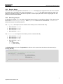
This application note describes a small setup for a single IOcab 8444opto to test the digital/analog input and ouput
lines. A test application configures the lines of the IOcab, measures them cyclically and displays the results on the
screen. The test application uses the XL Driver Library to access the IOcab 8444opto. The XL Driver Library can
be found on the Vector Driver Disk (included in CANcardXL delivery) or on our website www.vector.com.
Figure 1: Test application displaying values of digital and analog lines.
2.0 Setup
The example is split into two parts: A hardware setup and the configuration and measurement software.
The following chapters will describe each part in detail.
2.1 Hardware
This chapter describes the use case of the IOcab 8444opto, followed by the test setup.
2.1.1
Principle of Digital Lines
Since the digital outputs of the IOcab 8444opto are connected internally to electronic switches (photo MOS relays),
the digital outputs always need two digital lines: One line for the external supply and one general output line.
When the electronic switch is closed (by software), the applied voltage (or any other signal) is passed through to
the second line. This feature allows setting up any required output voltage in an application.
The IOcab 8444opto offers four switches between:
•
•
•
•
DIO0 and DIO1
DIO2 and DIO3
DIO4 and DIO5
DIO6 and DIO7
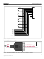
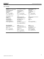
A digital output line always affects two digital lines, which cannot be configured as input. Figure 2 shows, which
lines are affected. Please refer to the IOcab 8444opto user manual for further details.
2
Application Note AN-INI-1-002
IOcab 8444opto Basic Example
1
2
DOUT0
DOUT0
1
2
DOUT1
DOUT1
1
2
DOUT2
1
9
2
10
3
11
4
12
5
13
6
14
7
15
8
1
9
2
10
3
11
4
12
5
13
6
14
7
15
8
DSUB15
DOUT2
1
2
DOUT3
DOUT3
DIN0
DIN1
DIN2
DIN3
DIN4
DIN5
DIN6
DIN7
DIN_GND
Figure 2: Schematic of digital lines.
The following figure shows an example.
V ext
external supply
software
controlled
switch
DIO0
1 DIO0 Digital Output
DIO1
9 DIO1 Digital Output
Figure 3: Externally supplied digital output. Output at DIO1 can be controlled by software.
3
Application Note AN-INI-1-002
IOcab 8444opto Basic Example
2.1.2
Principle of Analog Lines
The analog lines of the IOcab8444 can be freely configured as inputs or outputs. The maximum output level is
4096 mV. Figure 4 shows a small test setup without an external supply.
14 AIO0 Analog Output
7 AIO1 Analog Input
software
controlled
switch
15 AIO2 Analog Input
8 AIO3 Analog Input
Figure 4: Analog output and inputs. Inputs AIO2…AIO3 controlled by push buttons.
2.1.3
Example Setup
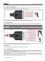
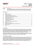
The following figure shows the complete setup of the IOcab8444 example. You will note that the output DIO0 is
supplied by the IOcab itself through AIO0. The switch between DIO0 and DIO1 controls the inputs DIO2 and DIO3.
Note:
Connecting output DIO1 to input DIO4…DIO7 has no effect in this example, since the supplied
voltage (4.096 V) is below the switch threshold (Schmitt trigger) of DIO4…DIO7. These switches
need at least 4.7 V to be turned on.
14 AIO0 Analog Output
Vext
analog
test setup
7 AIO1 Analog Input
15 AIO2 Analog Input
software
controlled
switch
DIO0
8 AIO3 Analog Input
DIO1
1 DIO0 Digital Output
9 DIO1 Digital Output
2 DIO2 Digital Input
10 DIO3 Digital Input
digital
test setup
Figure 5: Setup with digital and analog lines. Digital output supplied by AIO0.
2.2 Software
This chapter describes the principles of the IOcab 8444opto configuration.
2.2.1
Test Application
This example uses the xlDAIOexample which is delivered by the XL Driver Library (sources of xlDAIOexample are
available for C/C++ and C#). The application configures the IOCab 8444opto as previously described and starts
measuring the input pins. The results are displayed on the screen.
xlDAIOexample follows the general function call sequence as described in XL Driver Library - Description.pdf.
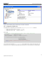
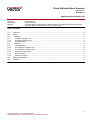
After the driver has been opened, the IOcab hardware settings are read (e.g. which CANcardXL channel is being
used). The settings are listed in the Vector Hardware Config tool.
4
Application Note AN-INI-1-002
IOcab 8444opto Basic Example
Figure 6: Vector Hardware Config. IOcab 8444opto connected to CANcardXL.
2.2.2
Configuration of Digital Lines
The digital lines are configured by the XL API function xlDAIOSetDigitalParameters as follows:
•
•
Digital output: DIO0 and DIO1 (bit mask = 00000011)
Digital inputs: DIO2…DIO7
(bit mask = 11111100)
Source code:
// DIO0/DIO1 = Output (0b00000011), DIO2...DIO7 = Input (0b11111100)
switchMask
= SWITCH_DIO0_DIO01;
digitalOutputMask = OUTPUT_DIO0_DIO01;
digitalInputMask = DIO_ALL & (~digitalOutputMask);
if (xlDAIOSetDigitalParameters(g_xlPortHandle,
g_xlChannelMask,
digitalInputMask,
digitalOutputMask)) {
printf("\nERROR: xlDAIOSetDigitalParameters failed\n");
return 0;
}
You will notice that the parameter digitalInputMask sets all digital IO lines, except for the output lines. This
ensures that no line is configured as input AND output at the same time. This would lead to an undefined state.
5
Application Note AN-INI-1-002
IOcab 8444opto Basic Example
2.2.3
Configuration of Analog Lines
The analog lines are configured by the XL API function xlDAIOSetAnalogParameters as follows:
•
•
Analog output: AIO0
(bit mask = 0001)
Analog inputs: AIO1…DIO3 (bit mask = 1110)
Source code:
// AIO0 = Output (0b0001), AIO1...AI03 = Input (0b1110)
analogOutputMask = AIO0;
analogInputMask = AIO_ALL & (~analogOutputMask);
if (xlDAIOSetAnalogParameters(g_xlPortHandle,
g_xlChannelMask,
analogInputMask,
analogOutputMask, 0x00)) {
printf("\nERROR: xlDAIOSetAnalogParameters failed\n");
return 0;
}
You will notice that the parameter analogInputMask sets all analog IO lines, except for the output lines. This
ensures that no line is configured as input AND output at the same time. This would lead to an undefined state.
2.2.4
Finish the Configuration
After the digital and analog lines have been configured, the channel on the CANcardXL (with plugged IOcab) is
activated. Afterwards, the analog output level on AIO0 is set to 4096 mV by use of the XL API function xlDAIOSetAnalogOutput. The value is stored in the variable outputMilliVolt.
Source code:
// Activate Channel
if (xlActivateChannel(g_xlPortHandle, g_xlChannelMask, XL_BUS_TYPE_DAIO, 0)) {
printf("\nERROR: xlActivateChannel failed!\n");
return 0;
}
printf(" >> Channel Activated.\n");
// Set AIO0 (defined output) to maximum voltage
if (xlDAIOSetAnalogOutput(g_xlPortHandle, g_xlChannelMask, outputMilliVolt, 0, 0,
0)) {
printf("\nERROR: xlDAIOSetAnalogOutput failed\n");
return 0;
}
Finally, a measurement frequency is set up which generates xlEvents cyclically. This event contains measured
data, which is received through the hardware queue. The frequency used in this example is 500 ms.
// Measure cyclically analog and digital ports
if (xlDAIOSetMeasurementFrequency(g_xlPortHandle,
g_xlChannelMask,
frequency)) {
printf("\nERROR: xlDAIOSetMeasurementFrequency failed\n");
return 0;
}
6
Application Note AN-INI-1-002
IOcab 8444opto Basic Example
2.2.5
Receive Queue
The Rx thread of the test application receives the xlEvents and displays the single values on the screen. All analog values can be accessed by an index in the tag data value_analog. The digital data contains the state of all
digital lines (including outputs). A bit mask is required in order to display the value of each single digital line. See
the source code for further details.
2.2.6
Switching Outputs
As described in chapter 2.1.1, the switch of the digital outputs has to be controlled by software. This is done by the
API function xlDAIOSetDigitalOutput. While outputMask selects one or more switches, valuePattern
defines the state of the selected switches.
The outputMask bit sequence for the switches is as follows (can be combined with OR):
•
•
•
•
DIO0 and DIO1: 0b0001
DIO2 and DIO3: 0b0010
DIO4 and DIO5: 0b0100
DIO6 and DIO7: 0b1000
The valuePattern bit sequence is as follows (can be combined with OR):
•
•
•
•
DIO0 and DIO1: 0b000x
DIO2 and DIO3: 0b00x0
DIO4 and DIO5: 0b0x00
DIO6 and DIO7: 0bx000
x can be:
x = 0 (switch open),
x = 1 (switch closed)
In xlDAIOexample the function ToggleSwitch is defined, which opens/closes all switches simultaneously by
pressing [ENTER].
void ToogleSwitch()
{
//closes/opens all relays at the same time
switchState = ~switchState;
if (xlDAIOSetDigitalOutput(g_xlPortHandle,
g_xlChannelMask,
switchMask,
switchState)) {
printf("\nERROR: xlDAIOSetDigitalOutput failed\n");
}
}
7
Application Note AN-INI-1-002
IOcab 8444opto Basic Example
3.0 Measuring Examples
After the example setup (see chapter 2.1.3) is done, the test application can be executed. Every 500 ms the test
application measures the lines of the IOcab 8444opto and displays the values.
When DIO0 is connected to AIO0, you will get the following output on the screen:
Example 1 (no external supply)
AIO0
4032mV
Measured value of set output voltage (4096mV).
AIO1
0mV
No input applied.
AIO2
0mV
No input applied.
AIO3
0mV
No input applied.
Relays selected
DIO/D01
The first switch is selected.
Relays state
OFF
DIO1 not connected to (supplied) DIO0. No output.
Digital Port
DIO7
DIO6
DIO5
DIO4
DIO3
DIO2
DIO1
DIO0
value
0
0
0
0
0
0
0
1
(1)
The following output will be displayed, when AIO2 has been connected with a wire to AIO0, the switch at DIO/DIO1
has been selected and turned on by software:
Example 2 (no external supply)
AIO0
4032mV
Measured value of set output voltage (4096mV).
AIO1
0mV
No input applied.
AIO2
4032mV
AIO2 connected to AIO0.
AIO3
0mV
No input applied.
Relays selected
DIO/D01
The first switch is selected.
Relays state
ON
DIO1 connected to (supplied) DIO0.
Digital Port
DIO7
DIO6
DIO5
DIO4
DIO3
DIO2
DIO1
DIO0
value
0
0
0
0
0
0
1
1
(3)
If an external supply is used, the digital input lines DIO4…DIO7 can also be used:
Example 3 (external supply)
AIO0
0mV
No input applied.
AIO1
0mV
No input applied.
AIO2
0mV
No input applied.
AIO3
0mV
No input applied.
Relays selected
DI6/D07
The last switch is selected.
Relays state
ON
DIO7 is connected to (ext. supplied) DIO6.
Digital Port
DIO7
DIO6
DIO5
DIO4
DIO3
DIO2
DIO1
DIO0
value
1
1
0
0
0
0
0
0
(C0)
8
Application Note AN-INI-1-002
IOcab 8444opto Basic Example
4.0 Contacts
Germany
and all countries not named below:
Vector Informatik GmbH
Ingersheimer Str. 24
70499 Stuttgart
GERMANY
Phone: +49 711-80670-0
Fax:
+49 711-80670-111
E-mail: [email protected]
France, Belgium, Luxemburg:
United Kingdom, Ireland:
Vector GB Ltd.
Rhodium
Central Boulevard
Blythe Valley Park
Solihull, Birmingham
West Midlands B90 8AS
UNITED KINGDOM
Phone: +44 121 50681-50
E-mail: [email protected]
China:
Vector Informatik GmbH
Shanghai Representative Office
Suite 605, Tower C,
Everbright Convention Center
No. 70 Caobao Road
Xuhui District
Shanghai 200235
P.R. CHINA
Phone: +86 21 - 6432 5353 ext. 0
Fax: +86 21 - 6432 5308
E-mail: [email protected]
India:
Vector Informatik India Private Ltd.
4/1/1/1 Sutar Icon
Sus Road
Pashan
Pune 411021
INDIA
USA, Canada, Mexico:
Vector CANtech, Inc.
39500 Orchard Hill Pl., Ste 550
Novi, MI 48375
USA
Phone: +1 248 449 9290
Fax:
+1 248 449 9704
E-mail: [email protected]
Japan:
Vector Japan Co. Ltd.
Seafort Square Center Bld. 18F
2-3-12, Higashi-shinagawa, Shinagawa-ku
Tokyo 140-0002
JAPAN
Phone: +81 3 5769 7800
Fax:
+81 3 5769 6975
E-mail: [email protected]
Korea:
Vector Korea IT Inc.
#1406, Mario Tower,
222-12 Guro-dong, Guro-gu
Seoul, 152-848
REPUBLIC OF KOREA
Phone: +82 2 807 0600
Fax:
+82 2 807 0601
E-mail: [email protected]
Vector France SAS
168 Boulevard Camélinat
92240 Malakoff
FRANCE
Phone: +33 1 42 31 40 00
Fax:
+33 1 42 31 40 09
E-mail: [email protected]
Sweden, Denmark, Norway,
Finland, Iceland:
VecScan AB
Theres Svenssons Gata 9
41755 Göteborg
SWEDEN
Phone: +46 31 764 76 00
Fax:
+46 31 764 76 19
E-mail: [email protected]
Phone: +91 9673 336575
E-mail: [email protected]
9
Application Note AN-INI-1-002