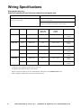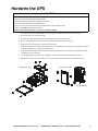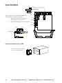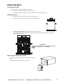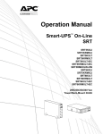
1
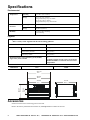
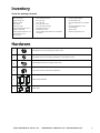
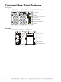
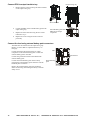
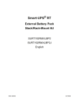
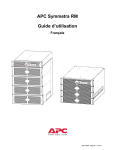
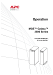
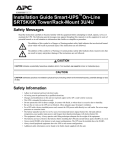
Installation and Operation
Smart-UPS™
Uninterruptible Power Supply
Stack/Rack-Mount 12U
SURT 15000/20000 VA
208/240 Vac
XLT
suo0648a
SURT 14000/18000 VA
200 Vac
XLJ
Product Description
The APC™ by Schneider Electric Smart-UPS™ is a high performance uninterruptible power supply (UPS). The UPS
provides protection for electronic equipment from utility power blackouts, brownouts, sags, and surges, small utility
power fluctuations and large disturbances. The UPS also provides battery backup power for connected equipment until
utility power returns to safe levels or the batteries are fully discharged.
This user manual is available on the enclosed CD and on the APC by Schneider Electric Web site, www.apc.com.
Important Safety Messages
Read the instructions carefully to become familiar with the equipment before trying to install, operate, service or
maintain it. The following special messages may appear throughout this manual or on the equipment to warn of
potential hazards or to call attention to information that clarifies or simplifies a procedure.
The addition of this symbol to a Caution product safety label indicates that a hazard exists that can result in
injury and product damage if the instructions are not followed.
The following safety messages may appear throughout this manual to warn of potential hazards.
CAUTION
CAUTION indicates a potentially hazardous situation which, if not avoided, can result in equipment damage and minor or moderate injury.
CAUTION
CAUTION indicates a potentially hazardous situation which, if not avoided, can result in equipment damage.
Safety and General Information
Inspect the package contents upon receipt. Notify the carrier and dealer if there is any
damage.
Read the Safety Guide supplied with this unit before installing the UPS.
• Adhere to all national and local electrical codes.
• This UPS is intended for indoor use only.
• Do not operate this UPS in direct sunlight, in contact with fluids, or where there is excessive dust or humidity.
• Be sure the air vents on the UPS are not blocked. Allow adequate space for proper ventilation.
• The battery typically lasts for two to five years. Environmental factors impact battery life. Elevated ambient
temperatures, poor quality utility power, and frequent short duration discharges will shorten battery life.
• Connect the UPS power cable directly to a wall outlet. Do not use surge protectors or extension cords.
• The equipment is heavy. Always practice safe lifting techniques adequate for the weight of the equipment.
• The batteries are heavy. Remove the batteries before installing the UPS and XLBP in rack-mount or stack
configurations.
• Always install external battery packs (XLBPs) at the bottom in rack-mount or stack configurations. The UPS
must be installed above the XLBPs.
• Always install peripheral equipment above the UPS in rack-mount or stack configurations.
• The UPS will recognize as many as 10 external battery packs connected to the UPS. However there is no limit to
the number of XLBPs that can be used with the UPS.
• The model and serial numbers are located on a small, rear panel label. For some models, an additional label is
located on the chassis under the front bezel.
• Always recycle used batteries.
• Recycle the package materials or save them for reuse.
SURT 14000/18000 VA 200 Vac XLJ,
15000/20000 VA 208/240 Vac XLT Stack/Rack-Mount 12U
1
Specifications
Environmental
Temperature
Maximum
Elevation
Operating
0° to 40° C (32° to 104° F)
Storage
-15° to 30° C (5° to 86° F)
charge UPS battery every six months
30° to 70° C (86° to 158° F)
charge UPS battery every three months
Operating
3,000 m (10,000 ft)
Storage
15,000 m (50,000 ft)
Humidity
0 to 95% relative humidity,
non-condensing
Physical
Weight
Refer to Safety Guide supplied with this unit for lifting guidelines.
UPS
66 kg (145 lbs)
Battery Pack
with eight battery modules
181 kg (400 lbs)
without battery modules
44 kg (96 lbs)
each battery module
17 kg (38 lbs)
Maximum number of external battery packs (XLBPs)
supported by Smart-UPS RT
Dimensions
UPS
10
Combined weights of UPS, battery pack and all
XLBPs installed in a rack must not exceed rack
weight limits.
XLBP
482 mm
19 in
465 mm
18.3 in
773 mm
30.4 in
suo0642a
102 mm
4 in
263 mm
10.4 in
432 mm
17 in
Accessories
Install accessories before connecting power to the UPS.
Refer to the APC by Schneider Electric Web site, www.apc.com for available accessories.
2
SURT 14000/18000 VA 200 Vac XLJ,
15000/20000 VA 208/240 Vac XLT Stack/Rack-Mount 12U
Inventory
Check the package contents
•
•
•
•
•
•
•
UPS
Input wiring tray
Output wiring tray
Display module
Front bezel
UPS serial cable
Network Management Card
(NMC) serial cable
• Ethernet jumper cable for rear
panel network access
25 cm (10 in)
–
–
–
–
–
–
–
–
Rail Kit
Four ornamental screws
Two cage nuts
Two rail cleats
Four pan head screws
Two rack-mount brackets
Eight flat head screws
Temperature sensor
refer to NMC documentation for installation
instructions
• Literature kit containing:
– Product documentation
– Documentation CD
– Network Management Card utility
CD
– Network Management Card
documentation
– Safety Guide
– Warranty registration card
Hardware
4
Pan head screws for securing rail cleats to unit
8
Flat head screws for securing rack-mount or tie brackets to unit
4
Ornamental screws for securing unit to rack
2
Cage nuts used in rack-mount installation
2
Rack-mount brackets
2
Rail cleats
SURT 14000/18000 VA 200 Vac XLJ,
15000/20000 VA 208/240 Vac XLT Stack/Rack-Mount 12U
3
Front and Rear Panel Features
Front panel
Display module
Display interface
PowerView cable connector
RJ45 connector
Serial Com
SmartSlot
Console/Serial Configuration Port
USB connector
Universal I/O ports
Ethernet Port 10/100 Base-T
Cold Start
su0146a
Rear panel
Input wiring tray
Network port
XLBP connectors
Output wiring tray
Ground screw
EPO Terminal
Cold Start/EPO reset
su0147a
4
SURT 14000/18000 VA 200 Vac XLJ,
15000/20000 VA 208/240 Vac XLT Stack/Rack-Mount 12U
Installation
CAUTION
DAMAGE TO EQUIPMENT OR PERSONNEL
• The equipment is heavy. Always practice safe lifting techniques adequate for the weight of the equipment.
• Remove the batteries from the battery pack and XLBPs before installation in rack-mount or stack configurations.
• When installing a UPS and XLBPs in a rack-mount or stack configuration, always install external battery packs at the
bottom of the rack with the UPS above the XLBPs.
• When installing peripheral equipment in a rack-mount or stack configuration, always install the UPS at the bottom of
the rack with the peripheral equipment above the UPS.
Failure to follow these instructions can result in equipment damage and minor or moderate injury
Stack Configuration
Total stack configuration height is recommended NOT to exceed 18U.
This is the equivalent of two XLBPs and one UPS.
8x
Four screws must be used to secure each tie bracket to the units,
(see diagram).
For detailed instructions on installing batteries and the battery
compartment doors, “Install units in rack” on this page or the manual.
UPS
Install tie brackets
ack
ery p
l batt
a
rn
exte
Four ornamental screws, supplied with the battery pack must be used to
secure each tie bracket to the units.
8x
su0165a
Refer to the “Install units in rack” on page 6 of the manual for cable
routing and bezel installation details.
Four tie brackets supplied
with each battery pack.
Rack-Mount Configuration
Install rack-mount brackets
y pac
atter
nal b
r
e
t
x
e
UPS
k
su0167a
Four flat head screws must be used to
secure each rack-mount bracket to the
unit.
4x
4x
Install rail cleats
ack
ery p
l batt
a
rn
exte
UPS
su0166a
Two pan head screws must be used to
secure each rail cleat to the unit.
2x
2x
Install rails in rack
For details on rail installation refer to the instructions included with the rail kit.
SURT 14000/18000 VA 200 Vac XLJ,
15000/20000 VA 208/240 Vac XLT Stack/Rack-Mount 12U
5
suo0667a
Install units in rack
Secure the UPS and the XLBP in the rack
using the cage nuts and ornamental screws
included in the package.
Four ornamental screws and two cage nuts
must be used to secure each unit.
The bottom hole of each rack-mount bracket
must be secured using an ornamental screw
in the threaded hole.
7 holes
suo0666a
A cage nut must be used in the top hole of
each rack-mount bracket when securing the
unit in the rack.
4x
7 holes
4x
Install battery modules
CAUTION
RISK OF EQUIPMENT DAMAGE
• Install all eight battery modules.
su0173a
Failure to follow these instructions can result in equipment damage
6
SURT 14000/18000 VA 200 Vac XLJ,
15000/20000 VA 208/240 Vac XLT Stack/Rack-Mount 12U
Communication Ports
Serial Com port and
display interface connector
Use only the supplied cable to connect to the serial port.
A standard serial interface cable is incompatible with the UPS.
Communication ports on the Network
Management Card
Refer to “Front and Rear Panel
Features” on page 4 for port
identification.
Refer to the NMC user manual for local configuration instructions.
Install PowerView Module
Before attaching the PowerView module to the UPS:
1. Loosen the two bracket screws on the back of the PowerView module.
a. Slide the bracket to the position that will accommodate the screw holes on the UPS.
b. Tighten the screws on the bracket.
2. Secure the PowerView module to the UPS using the two thumb screws attached to the module.
LOA
D ON
ON-B
ATT
ESC
su0161a
?
su0160a
BYP
ASS
FAU
LT
Connect the PowerView cable to the PowerView connector on the UPS.
su0159a
SURT 14000/18000 VA 200 Vac XLJ,
15000/20000 VA 208/240 Vac XLT Stack/Rack-Mount 12U
7
Route Network Cable
Network cable wiring front panel access
The NMC is installed in the SmartSlot located on the front of the UPS.
Connect a network cable (not supplied), to the network port on the NMC.
Cables connected to the UPS for front panel access must be routed through one of the notches in bezel.
su0177a
Network port on NMC
installed in SmartSlot
Network cable
Network cable wiring rear panel access
Network connection an be accessed from the RJ45 connector located on the rear panel of the UPS.
1.
Locate the RJ45 connector on the front panel of the UPS. Connect the jumper cable (supplied), to the NMC
RJ45 connector labeled NETWORK.
2.
Connect a network cable (not supplied), from a network device to the RJ45 connector on the rear panel of
the UPS.
Network port
Network cable
RJ45 connector
su0176a
Jumper cable
25.4 cm (10 in)
Network cable connected to rear
panel RJ45 connector
Network port
8
SURT 14000/18000 VA 200 Vac XLJ,
15000/20000 VA 208/240 Vac XLT Stack/Rack-Mount 12U
Emergency Power Off
The system power can be disabled in an emergency by closing a switch connected to the emergency power off
(EPO) system.
Wiring must be performed by a qualified electrician. Adhere to all local and national electrical codes.
The switch should be connected in a normally open switch contact. External voltage is not required; the switch is
driven by 24 V internal supply. In closed condition, 4 mA of current are drawn.
The EPO switch is internally powered by the UPS for use with non-powered switch circuit breakers.
The EPO circuit is considered a Class 2 circuit, (UL, CSA standards) and an SELV circuit (IEC standard).
EPO connector
located on rear panel
• Strip insulation from one end of each wire to be used for
connecting EPO.
• Insert screwdriver into the slot above terminal to be
wired. Insert stripped wire into terminal. Remove
screwdriver to secure wire in terminal. Repeat for each
terminal.
su0158a
EPO terminal
Both Class 2 and SELV circuits must be isolated from all primary circuitry. Do not connect any circuit to the EPO
terminal block unless it can be confirmed that the circuit is Class 2 or SELV. If circuit standard cannot be
confirmed, use a contact closure switch.
Use one of the following cable types to connect the UPS to the EPO switch.
• CL2: Class 2 cable for general use.
• CL2P: Plenum cable for use in ducts, plenums, and other spaces used for environmental air.
• CL2R: Riser cable for use in a vertical run in a floor-to-floor shaft.
• CLEX: Limited use cable for use in dwellings and for use in raceways.
• For installation in Canada: Use only CSA certified, type ELC, (extra-low voltage control cable).
• For installation in other countries: Use standard low-voltage cable in accordance with national and local
regulations.
SURT 14000/18000 VA 200 Vac XLJ,
15000/20000 VA 208/240 Vac XLT Stack/Rack-Mount 12U
9
Wiring Specifications
Wire gauges may vary.
Adhere to national and local electrical codes when wiring this unit.
Input Connections
Output Connections
Utility Input
Wire to L1, N/L2, ground
Hardwire
Wire to L1, N/L2, ground
PDU
XL battery pack PDU to UPS: Wire L1, N/L2, ground
System
SURT14K
SURT15K
SURT18K
SURT20K
Wiring
Voltage
Current
Full Load
(maximum)
External Input Circuit
Breaker
(typical)
Wire Size (typical)*
Input
200 Vac
80 A
100 A / 2-pole
25 mm2
(2 AWG)
Output
200 Vac
70 A
not required
25 mm2
(2 AWG)
Input
208/240 Vac
80 A
100 A / 2-pole
25 mm2
(2 AWG)
Output
208/240 Vac
72 A
not required
25 mm2
(2 AWG)
Input
200 Vac
100 A
125 A / 2-pole
35 mm2
(1 AWG)
Output
200 Vac
90 A
not required
35 mm2
(1 AWG)
Input
208/240 Vac
100 A
125 A / 2-pole
35 mm2
(1 AWG)
Output
208/240 Vac
96 A
not required
35 mm2
(1 AWG)
* Terminal screw tightening torque: 40 lb-in (4.5 N-m)
Acceptable input frequency range is 40 to 70 Hz.
Output voltage and frequency are user selectable only when UPS is in Load Disconnect mode.
Refer to display interface menu screens for available options.
10
SURT 14000/18000 VA 200 Vac XLJ,
15000/20000 VA 208/240 Vac XLT Stack/Rack-Mount 12U
Hardwire the UPS
CAUTION
RISK OF EQUIPMENT DAMAGE
•
•
•
•
•
Adhere to all national and local electrical codes.
Wiring should be performed by a qualified electrician.
Always connect the UPS to a grounded outlet.
Always connect ground wires between the UPS and the external battery packs.
Refer to the XLBP user manual for details.
Failure to follow these instructions can result in equipment damage
1. For input wiring only, install a utility circuit breaker in accordance with local electrical codes.
2. Switch the utility circuit breaker OFF.
3. Remove the screws that secure the covers and take the covers off of the trays.
4. Remove the appropriate circular knockouts from the input and output wiring trays.
5. Remove the five screws that secure the strain relief bar.
6. Remove the appropriate jumpers for input power source compatibility and output wiring options. Refer to
“Wiring Specifications” on page 10 in this manual.
7. Insert the cables through the knockout holes to the terminal blocks. Connect the ground terminal before
connecting any other terminal.
8. Use an appropriate strain relief (not supplied), on the hardwired input and output power cables.
9. Replace the wiring tray covers. Failure to do so can result in personal injury or equipment damage.
10.
Input Wiring Tray
suo0671a
suo0672a
Output Wiring Tray
5x
Strain Relief Bar
SURT 14000/18000 VA 200 Vac XLJ,
15000/20000 VA 208/240 Vac XLT Stack/Rack-Mount 12U
11
Input Hardwire
L1
Neutral/L2
Ground
N/L2
Be sure the ground wire conductor and insulator are
securely fastened. To connect ground wire:
L1
Lug A
1.
Strip cable of insulation, exposing wire.
Secure exposed wire with lug “A”.
2.
Secure insulated portion of cable with lug “B”.
Lug B
Lug A
Lug B
Lug B
su0155a
Lug A
Stripped wire
su0154a
Insulated wire
Secure input wiring tray to UPS using
three screws attached to the tray.
12
SURT 14000/18000 VA 200 Vac XLJ,
su0170a
Install input hardwire tray in UPS
15000/20000 VA 208/240 Vac XLT Stack/Rack-Mount 12U
Output Hardwire
Connect load to UPS
There are two ways to connect equipment to the UPS.
• Hardwire the equipment through the output wiring tray.
• Connect the equipment using the six output receptacles on the external battery pack.
Hardwire the load
1. Remove appropriate circular knockout from output wiring tray.
su0350a
2. Install appropriate strain relief (not supplied), for hardwire cables.
3. Connect ground terminal first. Then connect the remaining wires.
Route wires through the knockout hole to the terminal blocks. See diagram below. Refer to “Wiring
Specifications” on page 10.
CAUTION
su0180b
Be sure the OSJ is secured to the output wiring
tray using the five screws supplied.
Install output hardwire tray in UPS
Tighten the screws to secure the tray to the UPS.
SURT 14000/18000 VA 200 Vac XLJ,
15000/20000 VA 208/240 Vac XLT Stack/Rack-Mount 12U
su0348a
Insert the wiring tray into the appropriate slot on the UPS rear
panel.
13
Connect PDU to output hardwire tray
Remove the five screws securing the strain relief bar
on the output wiring tray.
su0169a
1.
Output wiring tray
5x
Strain relief bar
Connect the PDU on the external battery pack to the
output wiring tray.
3.
Replace the strain relief bar using the five screws
removed in step 1.
4.
Replace the covers using the screws removed
preciously.
External battery pack with
PDU and six output
receptacles
su0156b
2.
Connect the load using external battery pack connectors
The PDU must be connected to the output wiring tray.
Refer to “Connect PDU to output hardwire tray” on
this page.
Connect the load to the UPS using the six output
receptacles on the external battery pack. Connect the
external battery pack to the UPS.
UPS
Ground wire
Connect the ground wire between the UPS and the
external battery pack.
Refer to the external battery pack user manual for
details on removing and securing the battery connector
safety covers.
14
SURT 14000/18000 VA 200 Vac XLJ,
External battery
pack
su0345a
Connect the external battery pack to the UPS by
plugging the external battery pack connectors into the
UPS rear panel connectors.
Six output connectors
15000/20000 VA 208/240 Vac XLT Stack/Rack-Mount 12U
Start Up
Connect Battery Modules
CAUTION
RISK OF EQUIPMENT DAMAGE
• Connect all eight battery modules.
• Replace the battery compartment doors.
• Tighten the screws to secure the battery compartment doors.
su0174a
su0339a
Failure to follow these instructions can result in equipment damage
Install Bezels
There is a single latch on either side of the UPS bezel.
Su0175b
There are two latches on either side of the battery pack
and XLBP bezels.
Connect Load to UPS
Connect equipment to the UPS. Refer to “Output Hardwire” on page 13.
Each connected load must be switched OFF.
The battery charges to 90% capacity during the first three hours of normal operation. Do not expect full battery run
capability during this initial charge period.
Refer to the APC by Schneider Electric Web site, www.apc.com for battery runtimes.
Where appropriate use an APC extension battery cable. For ordering details contact a dealer or APC through the
Web site www.apc.com.
Connect Power to UPS and Load
1. Connect input power to the UPS.
2. Check the PowerView display interface for messages.
3. Turn on the connected equipment using the PowerView display interface menu option, Turn Load On
accessed through the Control menu screen. Refer to “Menu Tree” on page 17 and “Menu screens map” on
page 20.
SURT 14000/18000 VA 200 Vac XLJ,
15000/20000 VA 208/240 Vac XLT Stack/Rack-Mount 12U
15
Operation
The UPS has three operation mode options.
Normal operation
During normal operation, the UPS double converts utility power to conditioned power for the connected load.
Battery operation
During battery operation, the UPS provides power to the connected load from batteries for a finite period of time.
The UPS transfers to battery operation if the supply of utility power fails or is outside predefined limits.
Bypass operation
Bypass mode is reached either as a user selection or automatically.
• Bypass mode can be selected through the Control menu screen on the PowerView display.
• The UPS will automatically switch into bypass mode if:
– Both normal and battery operation modes are unavailable
– An output overload condition occurs
– The UPS has an internal fault
During bypass operation the utility power is connected to the load, bypassing the internal converters. If bypass
mode becomes unavailable the UPS will automatically switch to mains power. In the event that mains power is
unavailable the system will switch to battery power.
Battery LED
The battery LED is located on the front bezel of the XLBP. During normal operation the LED is not illuminated.
On start up the XLBP LED may illuminate and blink within the first minute. The LED should then extinguishes.
Refer to the XLBP User Manual for details on XLBP operation.
The four LEDs to the left of the LCD display
indicate the operational status of the UPS.
Chrg 000%
Load 000%
000Vin 000Vout 0Hz
1:1Runtime:00hr0m
The five navigation keys to the right of the LCD
display are used to select and open menu items, to
access information, change system parameters, and
to access context sensitive help.
a
LOAD ON
When LED illuminates green, the UPS supplies power to the load
b
ON BATT
When LED illuminates yellow, power to load flows from the batteries to the power module
c
BYPASS
When LED illuminates yellow, power to the load is supplied through bypass
d
FAULT
When LED illuminates red, a fault condition exists
e
LCD interface
Displays menu screens for alarms, status data, instructional help, and configuration items
f
UP /DOWN
Used to scroll through and select menu items
g
HELP key
h
ENTER
i
ESC
16
su0162b
PowerView Display Interface
arrow keys
key
key
Opens context sensitive help
Opens menu items and saves changes to system parameters
Returns to previous screen displayed
SURT 14000/18000 VA 200 Vac XLJ,
15000/20000 VA 208/240 Vac XLT Stack/Rack-Mount 12U
Navigating Menu Screens
Use the ESC key to navigate between menu screens.
Use the UP/DOWN arrow keys to scroll through the list of sub menus and commands on any screen.
arrow indicates that there are sub menus containing user selectable commands.
Use the ENTER key to navigate to a sub menu and to select user configurable commands.
To access the overview status screen on the LCD press
the ESC key.
su0193a
Chrg XXX%
Load XXX%
XXXVin XXXVout XHz
1:1Runtime:XXhrXm
To access the main menu screen from the overview
status screen, press the ENTER key.
Logging
Display
Diags
Help
su0194a
Control
Status
Setup
Batteries
Main Menu Screen
From the main menu screen it is possible to command, configure, and monitor the system using the sub menu screens:
Control, Status, Setup, Logging, Display, Diags and Help (refer to sub menu screens section in this manual).
Use the UP/DOWN arrow keys to select the menu to be
accessed.
Logging
Control
Display
Diags
Help
su0197a
Status
Setup
Batteries
Press the ENTER key to open a sub menu screen.
Menu Tree
The menu tree provides an overview of the
top level menu screens.
Navigating sub menu screens
Use the UP/DOWN arrow keys to scroll
through the list of functions and commands
on a sub menu screen.
Overview Status
Screen
Main Menu
Screen
A
after the last entry on a sub menu,
indicates a continuation of the function/
command list.
Chrg 000%
Load 000%
000Vin 000Vout 0Hz
1:1Runtime:00hr0m
Control
Status
Setup
Batteries
Use the UP/DOWN arrow keys to view the
remaining entries in the list.
Control
Status
Logging
Display
Diags
Help
Setup
Batteries
Logging
SURT 14000/18000 VA 200 Vac XLJ,
Display
Diags
15000/20000 VA 208/240 Vac XLT Stack/Rack-Mount 12U
Help
su0206a
Use the ENTER key to select a command and
move to sub menus associated with that
function/command.
17
Configuration
UPS configuration options can be adjusted through the display interface or NMC
Configurables
Factory
Default
User Selectable Choices
Description
Setup/Settings/Shutdown
Low Batt Dur
2 min
2, 5, 7, 10, 15, 18, 20 min
The low battery warning beeps become continuous when two
minutes of runtime remains.
Change the warning interval to a higher setting if the operating
system requires a longer interval for shutdown.
Shutdown Dly
20 sec
20, 180, 300, 600 sec
Set the interval between the time when the UPS receives a
shutdown command and the actual shutdown.
Turn On Dly
0 sec
0, 60, 180, 300 sec
Specify the time the UPS will wait after the return of utility
power before turn-on (to avoid branch circuit overloads).
Return Bat Cap
0%
0%, 15%, 25%, 35%, 50%,
60%, 75%, 90%
Specify the percentage to which batteries will be charged
following a low-battery shutdown before powering connected
equipment.
Setup/Settings/Default
Default
Set all UPS settings to factory defaults
Setup/Settings/System
System/Voltage
Output 200 V 200 V
Output 208 V 208 V, 240 V
Allows user to select UPS output voltage. This feature is
available ONLY when the load is OFF.
Use voltage setting applicable to region.
System/Frequency Auto
50 Hz, 60 Hz
System/
Frequency/Range
50±3 Hz,
60±3 Hz
50±3 Hz, 50±0.1 Hz
60±3 Hz, 60±0.1 Hz
System/Slew Rate
1 Hz/sec
1, .5, .25 Hz/sec
Slew rate limits the rate of change of output frequency.
Whenever possible, output frequency tracks input frequency.
System/Cyclic
Chrg
OFF
OFF, ON
The cyclic charge feature shuts off battery charge power
periodically while the UPS is running on utility power, and the
batteries are fully charged.
The cycles are 10 hours on and 48 hours off.
This extends battery life.
System/
Auto Start
ON
ON, OFF
After a low battery shutdown, the UPS will automatically start
if utility power is available.
Sets allowable UPS output frequency. Whenever possible,
output frequency tracks input frequency.
This feature is available ONLY when the load is OFF.
Setup/Settings/Alarms
Alarm Thresholds/Load
14 kVA
14 kVA
2, 4, 6, 8, 10, 12, 14 kVA,
Never
15 kVA
15 kVA
5, 10, 15 kVA, Never
18 kVA
18 kVA
2, 4, 6, 8, 10, 12, 14, 16,
18 kVA, Never
20 kVA
20 kVA
5, 10, 15, 20 kVA, Never
If the connected load exceeds the load alarm threshold an
alarm is activated.
Alarm Thresholds/Runtime
All models
18
0
0, 5, 10, 15, 30, 45 min;
1-8 hrs
SURT 14000/18000 VA 200 Vac XLJ,
When remaining battery runtime is at or below the selected
runtime threshold, an alarm is activated.
15000/20000 VA 208/240 Vac XLT Stack/Rack-Mount 12U
Configurables
Factory
Default
User Selectable Choices
Description
Setup/Settings/Clock
Date
The date and time functions are used to time-stamp events in
the event log. To avoid inaccuracies, change the time setting to
reflect day light saving time where applicable.
Time
Setup/Settings/Other
Self Test
14 days
7, 14 days, At Pwr On, OFF Set interval at which UPS will execute a self-test.
User ID
Ext Bat Cap
Uniquely identify UPS, (i.e. server name or location) for
network management purposes.
0 Ah
0-200 Ah
Press the ENTER key. Use the UP/DOWN arrow keys to select
desired value. Press the ENTER key to move to next digit.
Press the ENTER key after selecting final value, to lock in
battery capacity setting.
Display
Display Setup
Select language desired for viewing menu screens.
Language
0
0-7
Adjusts contrast between LCD text and back lighting.
Beep at
PwrFail +30
PwrFail +30, PwrFail,
Low Bat, Never
An alarm can be set to warn of an imminent power failure, a
power failure that will occur in 30 seconds, or when a low
battery condition occurs.
Volume
Low
Off, Low, Medium, High
Sets beeper volume.
Key Click
Off
Off, On
Sets key click volume to On or Off.
Contrast
Beeper Setup
SURT 14000/18000 VA 200 Vac XLJ,
15000/20000 VA 208/240 Vac XLT Stack/Rack-Mount 12U
19
Menu screens map
Refer to the Configuration tables on the previous pages for specific system configuration settings.
Logging
Display
Diags
Help
Control
Status
Setup
Batteries
Logging
Display
Diags
Help
Control
Status
Setup
Batteries
UPS into Bypass
Do Self Test
Simulate Power Fail
Start Runtime Cal
Vin
Vbyp
Vout
1
2
3
Iin
Turn Load Off
Ibyp
Iout
su0199a
1
2
3
kW
kVA
1
2
3
Settings:
Shutdown
Default
System
Shutdown
Frequencies
Mains
Bypass
Output
Logging
Display
Diags
Help
Load
Bat Voltage
Bat Charge
Runtime
Alarms
Clock
Other
Bat AmpHr
UPS Temp
Low Batt Dur
Shutdown Dly
Turn On Dly
Return Bat Cap
Alarm Thresholds
Load
Runtime
Set all UPS settings
to Factory Defaults
NO, ABORT
YES, Set to Defaults
Default
Output Frequency Options: Auto Sensing; 50 Hz; 60 Hz
Voltage
Frequency
Frq. Range
1 Phase Mains On
System
su0200a
Control
Status
Setup
Batteries
50 Hz frequency range: 50±3 Hz; 50±0.1 Hz
60 Hz frequency range: 60±3 Hz; 60±0.1 Hz
Slew Rate
Cyclic Chrg
Auto Start
Clock
Other
Alarm Thresholds
Load
Runtime
Clock: The date and time functions are used to time stamp events in the
event log. To avoid inaccuracies, change the time setting to reflect day light
saving time where applicable.
Date
Time
Other Settings
Self Test
UPS ID
Ext Bat Cap
su0201a
Alarms
Ext Bat Cap: Press
desired value. Press
. Use the UP/DOWN arrow keys to select the
to move to the next digit. Press
after
selecting the final value, to lock in the battery capacity setting.
20
SURT 14000/18000 VA 200 Vac XLJ,
15000/20000 VA 208/240 Vac XLT Stack/Rack-Mount 12U
Troubleshooting Display Messages
Use the table below to solve minor installation and operation problems. Refer to the APC by Schneider Electric
Web site, www.apc.com for assistance with complex UPS problems.The PowerView reports various messages on
the display, including alarm status and changes in system configuration. This section lists all the PowerView
display messages, the reason for the message, and the appropriate corrective action.
Messages may occur simultaneously. If this happens, be sure to review all of the messages for a better
understanding of the system condition.
Condition
Start Up
PowerView Display
Message
Reason for Message
Corrective Action
#Batteries changed since
last ON.
At least one battery module has been
added or removed from the UPS since the
last time the Pwr ON command was
issued.
No corrective action necessary. Proceed
with the start up.
Automatic Self Test
Started.
The UPS has started preprogrammed
battery test.
Batt capacity less than
Return Batt Cap.
The battery capacity of the UPS is less
than the user specified minimum battery
capacity required to turn on the load.
Option 1) Abort the start up and
allow batteries to recharge.
Option 2) Continue start up, with less
than minimum battery capacity.
General Status
Module Failure
System Start Up
Configuration Failed.
System configuration error: Start up
diagnostic fault.
Check for other alarms.
Mains: Site Wiring Fault
Input and Output Jumpers are not
configured correctly
Check input wiring tray jumpers and
output shorting jumper for compatibility.
Refer to the Input/Output Jumper
Configurations table in this manual.
If the problem persists contact APC by
Schneider Electric Customer Support.
Refer to Contact Information in this
manual.
Bypass Not Available Wrong Ph Seq
Check bypass jumpers in input wiring
tray and output shorting jumper for
compatibility. Check bypass phases for
positive sequence. Refer to the Input/
Output Jumper Configurations table in
this manual.
Bypass: Site Wiring Fault
Check bypass jumpers in input wiring
tray and output shorting jumper for
compatibility. Refer to the Input/Output
Jumper Configurations table in this
manual.
# of batteries increased.
At least one battery pair has been added
to the system.
# of batteries decreased.
At least one battery pair has been
removed from the system.
# External Battery Packs
increased.
At least one external battery pack has
been connected to the UPS.
# External Battery Packs
decreased.
At least one external battery pack has
been disconnected from the UPS.
Bad Battery Pair.
A battery pair has failed and requires
replacement.
SURT 14000/18000 VA 200 Vac XLJ,
No corrective action is necessary.
Refer to battery pair installation in the
external battery pack user manual.
15000/20000 VA 208/240 Vac XLT Stack/Rack-Mount 12U
21
Condition
Threshold
Alarm
PowerView Display
Message
Load Power Is Above
Alarm Limit.
Reason for Message
The load has exceeded the user specified
load alarm threshold.
Corrective Action
Option 1) Use the display interface to
raise the alarm threshold.
Option 2) Reduce the load
Load Is No Longer Above
Alarm Threshold.
The load exceeded the alarm threshold.
The situation has been corrected. Either
because the load decreased or the
threshold was increased.
Min Runtime Restored.
The system runtime dropped below the
configured minimum and has been
restored:
No corrective action is necessary.
1) Additional battery modules were
installed.
2) The existing battery modules were
recharged.
3) The load was reduced.
4) The user specified threshold was
decreased.
22
SURT 14000/18000 VA 200 Vac XLJ,
15000/20000 VA 208/240 Vac XLT Stack/Rack-Mount 12U
Condition
General Fault
PowerView Display
Message
Reason for Message
Corrective Action
Need Bat Replacement.
One or more battery pairs are in need of
replacement.
Refer to battery installation procedure.
No Batteries Are
Connected.
No battery power is available.
Check that batteries are installed and
connected properly.
Discharged Battery.
The UPS is on battery operation and the
battery charge is low.
Shut down the system and the load or
restore the incoming voltage.
Low- Battery.
The UPS is on battery operation and the
battery charge is low.
Weak Batt(s) Detected.
One or more weak battery pairs detected
(only applicable for internal battery
modules).
Replace the weak battery pairs.
Batt Temperature Exceeded
Upper Limit.
The temperature of one or more battery
packs has exceeded system
specifications.
Contact APC by Schneider Electric
Customer Support. Refer to Contact
Information in this manual.
Battery Over-Voltage
Warning.
The battery voltage is too high and the
charger has been deactivated.
Runtime Is Below Alarm
Threshold.
The predicted runtime is lower than the
user specified minimum runtime alarm
threshold. Either the battery capacity has
decreased, or the load has increased.
Reduced Runtime.
Option 1) Allow the batteries to
recharge.
Option 2) If possible, increase the
number of battery modules.
Option 3) Reduce the load.
Option 4) Decrease the alarm threshold.
Shutdown Due To Low
Battery.
The UPS shutdown while on battery
operation.
No corrective action is necessary.
Bypass Not Available Input
Freq/Volt out Of Range.
The frequency or voltage is out of
acceptable range for bypass. This
message occurs when the UPS is online.
Correct the input voltage to acceptable
frequency or voltage.
Mains Not Available. Input
Frq/Volt Out of Range.
The frequency or voltage is out of
acceptable range for normal operation.
Emergency PSU Fault.
Redundant Emergency Power Supply
Unit (PSU) is not working. Internal
diagnostic fault. The UPS will continue to
operate normally.
SURT 14000/18000 VA 200 Vac XLJ,
Note: Should this situation reoccur,
consider increasing battery capacity.
Contact APC by Schneider Electric
Customer Support. Refer to Contact
Information in this manual.
15000/20000 VA 208/240 Vac XLT Stack/Rack-Mount 12U
23
Condition
General Fault
PowerView Display
Message
Reason for Message
Corrective Action
Fan Fault
A fan has failed.
Static Bypass Switch Fault.
The static bypass switch has failed.
Contact APC by Schneider Electric
Customer Support. Refer to Contact
Information in this manual.
System Failure Detected by
Surveillance.
The system has detected an internal error.
Check for other alarms.
System Not Synchronized
to Bypass.
System cannot synchronize to bypass
mode.Bypass mode may be unavailable.
If the problem persists contact APC by
Schneider Electric Customer Support.
Refer to Contact Information in this
manual.
Option 1) Decrease input frequency
sensitivity.
Contact APC by Schneider Electric
Customer Support. Refer to Contact
Information in this manual.
Option 2) Correct bypass input voltage
to provide acceptable frequency or
voltage.
24
UPS In Bypass Due To
Fault.
The UPS has transferred to bypass mode
due to a fault.
Contact APC by Schneider Electric
Customer Support. Refer to Contact
Information in this manual.
UPS In Bypass Due To
Overload.
The load has exceeded the power
capacity.
Decrease the load.
UPS Is Overloaded.
The load has exceeded the system power
capacity.
Option 1) Decrease the load.
SURT 14000/18000 VA 200 Vac XLJ,
Option 2) Check the load distribution on
the three phases through the PowerView
display. If the load is unevenly
distributed, adjust the load distribution.
15000/20000 VA 208/240 Vac XLT Stack/Rack-Mount 12U
Maintenance
Replace battery modules
This UPS has easy to replace, hot swappable battery modules. Replacement is a safe procedure, isolated from
electrical hazards. You may leave the UPS and connected equipment on during the replacement procedure.
Once the batteries are disconnected the connected equipment is not protected from power outages.
Refer to the appropriate replacement battery user manual for battery module installation instructions. See your
dealer or contact APC by Schneider Electric at www.apc.com for information on replacement battery modules.
Be sure to deliver the used battery(s) to a recycling facility or ship it to APC by Schneider Electric
in the replacement battery packing material.
Service
If the unit requires service, do not return it to the dealer. Follow these steps:
1. Review the Troubleshooting section of the manual to eliminate common problems.
2. If the problem persists, contact APC by Schneider Electric Customer Support through the APC by
Schneider Electric Web site, www.apc.com.
a. Note the model number and serial number and the date of purchase. The model and serial
numbers are located on the rear panel of the unit and are available through the LCD display
on select models.
b. Call APC by Schneider Electric Customer Support and a technician will attempt to solve
the problem over the phone. If this is not possible, the technician will issue a Returned
Material Authorization Number (RMA#).
c. If the unit is under warranty, the repairs are free.
d. Service procedures and returns may vary internationally. Refer to the APC by Schneider
Electric Web site for country specific instructions.
3. Pack the unit in the original packaging whenever possible to avoid damage in transit. Never use foam
beads for packaging. Damage sustained in transit is not covered under warranty.
a. Always DISCONNECT THE UPS BATTERIES before shipping. The United States
Department of Transportation (DOT), and the International Air Transport
Association (IATA) regulations require that UPS batteries be disconnected before
shipping. The internal batteries may remain in the UPS.
b. External Battery Pack products are deenergized when disconnected from the associated
UPS product. It is not necessary to disconnect the internal batteries for shipping. Not all
units utilize an external battery pack.
4. Write the RMA# provided by Customer Support on the outside of the package.
5. Return the unit by insured, prepaid carrier to the address provided by Customer Support.
Transport the unit
1. Shut down and disconnect all connected equipment.
2. Disconnect the unit from utility power.
3. Disconnect all internal and external batteries (if applicable).
4. Follow the shipping instructions outlined in the Service section of this manual.
SURT 14000/18000 VA 200 Vac XLJ,
15000/20000 VA 208/240 Vac XLT Stack/Rack-Mount 12U
25
Two Year Limited Factory Warranty
Schneider Electric IT Corporation (SEIT), warrants its products to be free from defects in materials and
workmanship for a period of three (3) years excluding the batteries, which are warranted for two (2) years from the
date of purchase. The SEIT obligation under this warranty is limited to repairing or replacing, at its own sole
option, any such defective products. Repair or replacement of a defective product or parts thereof does not extend
the original warranty period.
This warranty applies only to the original purchaser who must have properly registered the product within 10 days
of purchase. Products may be registered online at warranty.apc.com.
SEIT shall not be liable under the warranty if its testing and examination disclose that the alleged defect in the
product does not exist or was caused by end user’s or any third person’s misuse, negligence, improper installation,
testing, operation or use of the product contrary to SEIT’s recommendations or specifications. Further, SEIT shall
not be liable for defects resulting from: 1) unauthorized attempts to repair or modify the product, 2) incorrect or
inadequate electrical voltage or connection, 3) inappropriate on site operation conditions, 4) Acts of God, 5)
exposure to the elements, or 6) theft. In no event shall SEIT have any liability under this warranty for any product
where the serial number has been altered, defaced, or removed.
EXCEPT AS SET FORTH ABOVE, THERE ARE NO WARRANTIES, EXPRESS OR IMPLIED, BY
OPERATION OF LAW OR OTHERWISE, APPLICABLE TO PRODUCTS SOLD, SERVICED OR
FURNISHED UNDER THIS AGREEMENT OR IN CONNECTION HEREWITH.
SEIT DISCLAIMS ALL IMPLIED WARRANTIES OF MERCHANTABILITY, SATISFACTION AND
FITNESS FOR A PARTICULAR PURPOSE.
SEIT EXPRESS WARRANTIES WILL NOT BE ENLARGED, DIMINISHED, OR AFFECTED BY AND
NO OBLIGATION OR LIABILITY WILL ARISE OUT OF, SEIT’S RENDERING OF TECHNICAL OR
OTHER ADVICE OR SERVICE IN CONNECTION WITH THE PRODUCTS.
THE FOREGOING WARRANTIES AND REMEDIES ARE EXCLUSIVE AND IN LIEU OF ALL
OTHER WARRANTIES AND REMEDIES. THE WARRANTIES SET FORTH ABOVE CONSTITUTE
SEIT’S SOLE LIABILITY AND PURCHASER’S EXCLUSIVE REMEDY FOR ANY BREACH OF SUCH
WARRANTIES. SEIT WARRANTIES EXTEND ONLY TO ORIGINAL PURCHASER AND ARE NOT
EXTENDED TO ANY THIRD PARTIES.
IN NO EVENT SHALL SEIT, ITS OFFICERS, DIRECTORS, AFFILIATES OR EMPLOYEES BE
LIABLE FOR ANY FORM OF INDIRECT, SPECIAL, CONSEQUENTIAL OR PUNITIVE DAMAGES,
ARISING OUT OF THE USE, SERVICE OR INSTALLATION OF THE PRODUCTS, WHETHER SUCH
DAMAGES ARISE IN CONTRACT OR TORT, IRRESPECTIVE OF FAULT, NEGLIGENCE OR
STRICT LIABILITY OR WHETHER SEIT HAS BEEN ADVISED IN ADVANCE OF THE POSSIBILITY
OF SUCH DAMAGES. SPECIFICALLY, SEIT IS NOT LIABLE FOR ANY COSTS, SUCH AS LOST
PROFITS OR REVENUE, WHETHER DIRECT OR INDIRECT, LOSS OF EQUIPMENT, LOSS OF USE
OF EQUIPMENT, LOSS OF SOFTWARE, LOSS OF DATA, COSTS OF SUBSTITUANTS, CLAIMS BY
THIRD PARTIES, OR OTHERWISE.
NOTHING IN THIS LIMITED WARRANTY SHALL SEEK TO EXCLUDE OR LIMIT SEIT’S
LIABILITY FOR DEATH OR PERSONAL INJURY RESULTING FROM ITS NEGLIGENCE OR ITS
FRAUDULENT MISREPRESENTATION OF TO THE EXTENT THAT IT CANNOT BE EXCLUDED
OR LIMITED BY APPLICABLE LAW.
To obtain service under warranty you must obtain a Returned Material Authorization (RMA) number from
customer support. Customers with warranty claims issues may access the SEIT worldwide customer support
network through the SEIT Web site: www.apc.com. Select your country from the country selection drop down
menu. Open the Support tab at the top of the web page to obtain information for customer support in your region.
Products must be returned with transportation charges prepaid and must be accompanied by a brief description of
the problem encountered and proof of date and place of purchase.
26
SURT 14000/18000 VA 200 Vac XLJ,
15000/20000 VA 208/240 Vac XLT Stack/Rack-Mount 12U
APC by Schneider Electric
Worldwide Customer Support
Customer support for this or any other APC by Schneider Electric product is available at no charge in any of
the following ways:
• Visit the APC by Schneider Electric Web site to access documents in the APC by Schneider Electric
Knowledge Base and to submit customer support requests.
– www.apc.com (Corporate Headquarters)
Connect to localized APC by Schneider Electric Web sites for specific countries, each of which
provides customer support information.
– www.apc.com/support/
Global support searching APC by Schneider Electric Knowledge Base and using e-support.
• Contact the APC by Schneider Electric Customer Support Center by telephone or e-mail.
– Local, country specific centers: go to www.apc.com/support/contact for contact information.
– For information on how to obtain local customer support, contact the APC by Schneider Electric
representative or other distributors from whom you purchased your APC by Schneider Electric
product.
Select models are ENERGY STAR® qualified.
For more information go to www.apc.com/site/recycle/index.cfm/energy-efficiency/energy-star/
© 2013 APC by Schneider Electric. APC, the APC logo, Smart-UPS and PowerChute are owned by Schneider
Electric Industries S.A.S., or their affiliated companies. All other trademarks are property of their respective
owners.
EN 990-3467B
07/2013