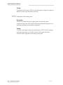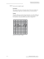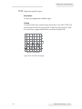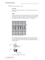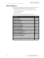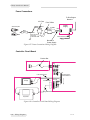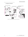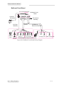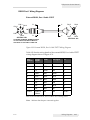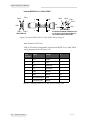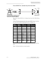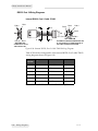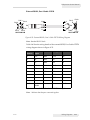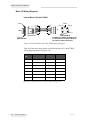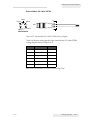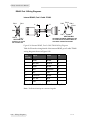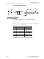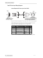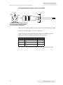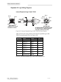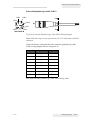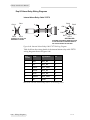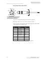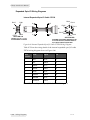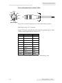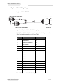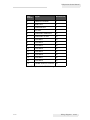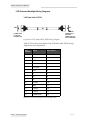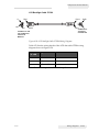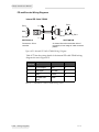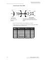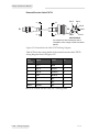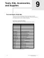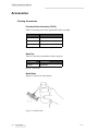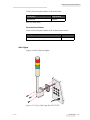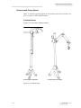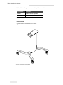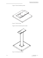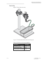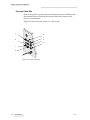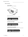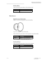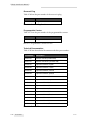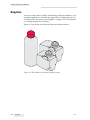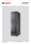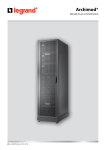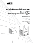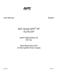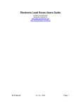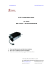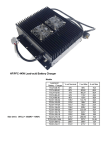
1
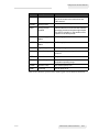
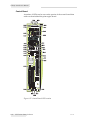
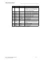
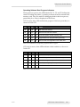
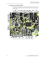
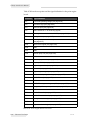
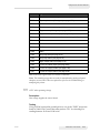
Videojet 1310 Service Manual
Table 8-50 lists the functions of the LEDs in the panel.
LED
Description
What does it mean when LED is lit?
RLOW
Reservoir Low
The ink level in the FMS reservoir is low.
ROVER
Reservoir Overfill
The ink level in the FMS reservoir has
exceeded its capacity. This results in a
printer fault.
ILOW
Ink Low
The fluid in the ink supply tank is low.
MLOW
Make-Up Low
The fluid in the make-up supply tank is low.
IBOT
Ink Bottle Present
An ink bottle has been inserted in the printer.
MFUL
Make-Up Full
The fluid in the make-up supply tank is full.
SW1
(not currently used)
Reserved for future expansion.
IFUL
Ink Full
The fluid in the ink supply tank is full
VAL2
and
VAL8
(not currently used)
Reserved for future expansion.
NWSH
Nozzle Wash Valve
The nozzle wash valve allows the flow of
make-up fluid across the face of the nozzle.
WPMP
Wash Pump Control
Valve
The wash pump control valve diverts ink into
the wash pump.
NVAL
Nozzle Valve
The nozzle valve allows ink to flow into the
nozzle.
NBYP
X-Flow Return
Valve
The X-flow return valve allows ink in the
nozzle to bypass the nozzle orifice and
return to the FMS reservoir.
IVAL
Ink Circulation Valve
The ink circulation valve allows the flow of
ink from the FMS reservoir into the ink
pump.
IADD
Ink Add Valve
The ink add valve allows the flow of ink from
the ink supply tank into the ink pump.
MADD
Make-Up Add Valve
The make-up add valve allows the flow of
make-up fluid from the make-up supply tank
into the FMS reservoir.
IBYP
Ink Bypass Valve
The ink bypass valve allows ink to bypass
the nozzle entirely and return to the FMS
reservoir.
CWSH
Catcher Wash Valve
The catcher wash valve allows the flow of
make-up fluid to the ink return block.
Table 8-50: Functions of LEDs on the Print Engine Circuit Board
8-56
LED Printer Status Indicators
Rev AD
Videojet 1310 Service Manual
LED
Description
What does it mean when LED is lit?
WRTN
Wash Return Valve
The wash return valve allows fluid at the
face of the nozzle to be returned into the
FMS reservoir.
APWR
Analog Power
-
AEN
Analog Circuits
Enabled
Indicates that the control board has released
the analog circuits on the print engine board.
This LED is normally on, but remains off for
a portion of the boot process.
+220
+220V Supply
Status
+220V supply is on.
+337
+337V Supply
Status
+337V supply is on.
HV
High Voltage Status
The high voltage is on.
PHA
Phase Stability
A phasing fault or a no signal fault has
occurred.
HTR
Heater Power
The printhead heater is on.
TEMP
Heater Temperature
The printhead temperature is within the
acceptable operating range.
VPMP
Vacuum Pump
The vacuum pump is on.
IPMP
Ink Pump
The ink pump is on.
Table 8-50: Functions of LEDs on the Print Engine Circuit Board (Continued)
Rev AD
LED Printer Status Indicators
8-57
Videojet 1310 Service Manual
Control Board
A number of LEDs can be seen on the portion of the control board that
sticks out from behind the print engine board.
Figure 8-17: Control Board LED Location
8-58
LED Printer Status Indicators
Rev AD
Videojet 1310 Service Manual
Table 8-51 lists the colors and functions of these LEDs.
LED
Color
Mnemonic
Meaning
D23
Green
PD1
Input from product detector 1. For some
product detectors, this light is normally
off, lighting to indicate a successful
product detect. For other product
detectors, this light is normally off,
extinguishing to indicate a detected
product.
D24
Red
ENC A
Indicates a pulse from shaft encoder A.
D25
Red
ENC B
Not currently used.
D27
Yellow
OUT 6
The output relay associated with the
Basic I/O port is active
D28
Red
SIREN
Not currently used.
D29
Red
RED
Not currently used.
D30
Yellow
YEL
Not currently used.
D31
Green
GRN
Not currently used.
D33
Yellow
INT ENC
Not currently used.
D34
Red
BKLSH
Not currently used.
D35
Green
DIR
Not currently used.
D36
-toD39
Yellow
T0, T1, T2
and T3
Indicate status of loading operating
software from the flash memory card.
See “Operating Software Boot Progress
Indicators” on page 8-61 for more
information.
D40
Green
JET1
Indicates communication with the print
engine board.
D41
Green
JET2
Not currently used.
D42
Red
RESET
The control board is in the process of
resetting itself.
D43
Green
BOOT
The control board is booting up.
D49
Green
5V
The 5V supply is on.
D50
Green
1.8V
The 1.8V supply is on.
D51
Green
3.3V
The 3.3V supply is on.
D52
Green
2.5V
The 2.5V supply is on.
Table 8-51: Control Board LED Functions
Rev AD
LED Printer Status Indicators
8-59
Videojet 1310 Service Manual
LED
Color
Mnemonic
Meaning
D56
Green
PWR GD
All four of the control board component
supplies (5V, 1.8V, 3.3V and 2.5V) are
on. All four of them are operating within
10% of the specified voltage.
D57
Green
CF2
Flash memory card 2 is being accessed.
D58
Green
CF1
Flash memory card 1 is being accessed.
D60
Green
CF2 on
Flash memory card 2 is on.
D61
Green
CF1 on
Flash memory card 1 is on.
D62
Green
USB LINK
Not currently used.
D63
Green
PD2
Not currently used.
D65
Yellow
IN 9
Indicates activity on the Basic I/O port’s
input line.
D69
Yellow
PRINT 1
Print Image in process.
D71
Yellow
PRINT 2
Not currently used.
Table 8-51: Control Board LED Functions (Continued)
8-60
LED Printer Status Indicators
Rev AD
Videojet 1310 Service Manual
Operating Software Boot Progress Indicators
During the boot process, the LEDs labeled T0, T1, T2, and T3 indicate the
status of loading the printer’s operating software from the inserted flash
memory card. They are useful for debugging faults in the boot process,
particularly if no video is displayed on the screen.
If T3 is not lit, these LEDs indicate the progress of the boot procedure, as
shown in Table 8-52.
T3
T2
T1
T0
Status
Off
Off
Off
On
Main has been entered.
Off
Off
On
Off
Normal mode has been chosen.
Off
On
Off
On
Found file system on flash memory card.
Off
On
On
Off
Programmed main programmable gate array.
Off
On
On
On
About to start main application from flash card.
Table 8-52: Indications of Operating Software Boot Progress
If T3 is lit, however, these LEDs indicate a fault condition, as shown in
Table 8-53.
T3
T2
T1
T0
Fault Indicated
On
Off
Off
Off
No flash memory card inserted.
On
Off
Off
On
No valid file system found on flash memory card.
On
Off
On
Off
No valid main gate array code found.
On
Off
On
On
No valid print engine gate array code found.
On
On
Off
Off
No valid nucleus code found.
Table 8-53: Fault Indications
Rev AD
LED Printer Status Indicators
8-61
Videojet 1310 Service Manual
Electronic Test Points
Introduction
Occasionally, it is necessary to analyze control circuit board or the print
engine circuit board to find the cause of printer faults and other
conditions. The test points on these circuit boards are used to help localize
or isolate a problem.
Electrical circuit checks may be necessary when the wiring breaks or
printhead failure is suspected. Use a digital voltmeter (DVM) or an
oscilloscope (when appropriate) to check voltage signal levels at the
printhead and the appropriate circuit board when checking the continuity
and resistance of a suspected wire or the functionality of a suspected
circuit or component.
8-62
Electronic Test Points
Rev AD
Videojet 1310 Service Manual
Print Engine Circuit Board (PEAP)
See Table 8-54 on page 8-64 to find the signal definition for each test point,
and see Figure 8-18 for the location of the test points on the print engine
circuit board.
Figure 8-18: Test Point Locations on Print Engine Circuit Board
Rev AD
Electronic Test Points
8-63
Videojet 1310 Service Manual
Table 8-54 lists the test points and the signal definition for the print engine
board.
Test Point
Signal Definition
TP1
+12V AUX operating voltage (see page 8-65).
TP2
+5V PEAP logic (see page 8-66).
TP3
+24V DC input (see page 8-66).
TP5
GND. Reference TP for observing signals.
TP6
Print engine board switched +24V DC (see page 8-66).
TP7
Analog enable (see page 8-67).
TP9
Print engine board ambient temperature
(see page 8-67).
TP10
Heater driver signal (see page 8-68).
TP18
GND
TP21
GND
TP25
Vacuum pump out (see page 8-68).
TP26
GND
TP27
Vacuum pump enable (see page 8-68).
TP30
Ink pump PWM (see page 8-69).
TP32
High voltage monitor (see page 8-69).
TP36
HV enable (see page 8-69).
TP38
High voltage arc signal (see page 8-70).
TP39
HV Manual trim program voltage (see page 8-70).
TP43
+337V DC out (see page 8-71).
TP45
GND
TP50
+337V DC voltage to charge amplifier (see page 8-71).
TP51
Charge amplifier output to printhead (see page 8-72).
TP53
GND
TP58
+220V DC enable (see page 8-72).
TP59
+220V DC converter output (see page 8-73).
TP64
Analog nozzle drive signal (see page 8-73).
TP65
GND
TP72
Digital nozzle clock signal (see page 8-73).
Table 8-54: Print Engine Board Test Points
8-64
Electronic Test Points
Rev AD
Videojet 1310 Service Manual
Test Point
Signal Definition
TP75
Peak detector DC tracking level for fly-by sensor (see page 8-74).
TP77
Bi-polar phase amplifier signal (see page 8-75).
TP78
GND
TP79
Phase comparator (see page 8-76).
TP80
Flight time amplifier signal (see page 8-77).
TP82
Flight time comparator output (see page 8-78).
TP84
Variable phase comparator reference (see page 8-79).
TP86
GND
TP87
GND
TP88
GND
TP89
GND
TP90
Ink pump RPM (see page 8-79).
TP92
Ink pump enable (see page 8-79).
TP94
High voltage status (see page 8-79).
TP95
+337V DC status output (see page 8-80).
TP96
+337V DC supply enable (see page 8-80).
TP97
+220V DC supply status (see page 8-80).
Table 8-54: Print Engine Board Test Points (Continued)
Note: The remaining test points are used for manufacturing testing only and,
therefore, are not listed. These test points are of no use in troubleshooting or
analyzing the printer.
TP1
+12 V AUX operating voltage
Description
This voltage supplies the control board.
Testing
Using a DVM, connect the ground probe to one of the “GND” test points
listed in Table 8-54. Connect the other probe to TP1. You should get a
reading between 11.00 and 13.00 volts.
Rev AD
Electronic Test Points
8-65
Videojet 1310 Service Manual
TP2
+5V logic
Description
This voltage is the logic supply for the print engine board.
Testing
Using a DVM, connect the ground probe to one of the “GND” test points
listed in Table 8-54 on page 8-64. Connect the other probe to TP2. You
should get a reading between 4.75 and 5.25 volts.
TP3
+24V DC input
Description
Indicates the voltage input to the print engine PCB from the +24V DC power
supply.
Testing
Using a DVM, connect the ground probe to one of the “GND” test points
listed in Table 8-54 on page 8-64. Connect the other probe to TP3. You
should get a reading of 24V DC ± 1.20 volts.
Note: However, you could get a reading as low as 21V DC or as high as 27V DC,
and the printer functions normally.
TP6
Print Engine Board +24V DC
Description
This is the switched +24V DC supply on the print engine board.
Testing
Using a DVM, connect the ground probe to one of the “GND” test points
listed in Table 8-54 on page 8-64. Connect the other probe to TP6. You
should get a reading of 24V DC ± 1.50 volts.
8-66
Electronic Test Points
Rev AD
Videojet 1310 Service Manual
TP7
Analog enable
Description
This signal is the microprocessor control line that enables power on the
print engine board. The control board can switch analog power ON or
OFF through this line.
Testing
Using a DVM, connect the ground probe to one of the “GND” test points
listed in Table 8-54 on page 8-64. Connect the other probe to TP7. A
reading of 0.7 volts or lower indicates an analog “ON” condition (Use the
20V scale). A reading of 2.5V or greater indicates an analog “OFF”
condition.
TP9
Print engine board ambient temperature
Description
Indicates the ambient temperature as measured by the print engine board.
When temperature over 70 °C is detected, the printer begins shutting
down to avoid damage to its systems.
Testing
Using a DVM, connect the ground probe to one of the “GND” test points
listed in Table 8-54 on page 8-64. Connect the other probe to TP9. The
temperature in degrees Celsius can be derived by inserting the voltage
reading at TP9 into the following formula:
Temperature = (<TP9 voltage reading> - 0.425) / 0.00625
For example, a reading of 0.625 volts, would produce the following
temperature calculation:
Temperature = (0.625 - 0.425) / 0.00625 = 32 °C
Rev AD
Electronic Test Points
8-67
Videojet 1310 Service Manual
TP10
Heater Driver Signal
Description
Pulse width modulated signal to heater element.
Testing
Using an oscilloscope, connect the ground probe to one of the “GND” test
points listed in Table 8-54 on page 8-64. Connect the other probe TP10. A
waveform is observed rising from 0 volts to +24V DC at a particular duty
cycle dependent on the heater temperature.
TP25
Vacuum pump out
Description
A DC level measured from +22 to +23V DC.
Testing
Using a DVM, connect the ground probe to one of the “GND” test points
listed in Table 8-54 on page 8-64. Connect the other probe to TP25.
TP27
Vacuum pump enable
Description
This signal is the microprocessor control line that enables the vacuum
pump. The control board can switch the vacuum pump ON or OFF
through this line.
Testing
Using a DVM, connect the ground probe to one of the “GND” test points
listed in Table 8-54 on page 8-64. Connect the other probe to TP27. A
reading of 0.7 volts or lower indicates a vacuum pump “OFF” condition
(Use the 20V scale). A reading of 2.5V or greater indicates a vacuum pump
“ON” condition.
8-68
Electronic Test Points
Rev AD
Videojet 1310 Service Manual
TP30
Ink pump PWM
Description
Duty cycle modulated timing signal to pump driver.
Testing
To verify that the ink pump is being driven, connect an oscilloscope to
TP30. A digital signal of 5kHz and a varying duty cycle is observed.
TP32
High voltage monitor
Description
Indicates the output level of the high voltage power supply. This voltage
is a positive reading.
This value is 1/1000 of the actual voltage at the printhead. (For example
+4.5 volts at TP32 equates to +4500 volts at the printhead.
Testing
Using a DVM, connect the ground probe one of the “GND” test points
listed in Table 8-54 on page 8-64. Connect the other probe to TP32. You
should get a reading of approximately 3 to 6 volts (Use the 20V scale).
TP36
HV enable
Description
This signal is the microprocessor control line that enables high voltage
supply. The control board can switch the high voltage supply ON or OFF
through this line.
Testing
Using a DVM, connect the ground probe one of the “GND” test points
listed in Table 8-54 on page 8-64. Connect the other probe to TP36. A
reading of 0.7 volts or lower indicates a high voltage “OFF” condition. A
reading of 2.5 volts or greater indicates a high voltage “ON” condition.
Rev AD
Electronic Test Points
8-69
Videojet 1310 Service Manual
TP38
High voltage arc signal
Description
This comparator indicates high voltage arcing. Arcing normally occurs in
the printhead when the printhead deflection plate gathers ink.
Testing
Connect an oscilloscope to TP38. If arcing is occurring, you will observe a
digital signal swinging to ground. The repetition rate varies depending on
the conditions.
TP39
HV manual trim program voltage
Description
This test point indicates the current setting of the nearby trimpot. When
jumper J14 is placed in the non-bar position, this trimpot can be used to set
the high voltage output manually.
Like the high voltage monitor test point, this value shows 1/1000 of the
actual voltage that would be used at the printhead. (For example +4.5
volts at TP39 equates to +4500 volts at the printhead.
Testing
Using a DVM, connect the ground probe to one of the “GND” test points
listed in Table 8-54 on page 8-64. Connect the other probe to TP39. For
proper printing and character height, the voltage can be set anywhere
between 3 to 6 volts.
8-70
Electronic Test Points
Rev AD
Videojet 1310 Service Manual
TP43
+337V DC out
Description
The output from the +337V converter is measured here.
Testing
Caution
PERSONAL INJURY. Use caution when measuring this voltage and
connecting or disconnecting the test leads.
Using a DVM, connect the ground probe to one of the “GND” test points
listed in Table 8-54 on page 8-64. Connect the other probe to TP43. You
should get a reading of +337 volts ± 1 volt.
TP50
+337V DC voltage to charge amplifier
Description
This voltage powers the charge amplifier.
Testing
Caution
ELECTRICAL SAFETY. Use caution when measuring this voltage
and connecting or disconnecting the test leads.
Using a DVM, connect the ground probe one of the “GND” test points
listed in Table 8-54 on page 8-64. Connect the other probe to TP50. You
should get a reading of +337 volts ± 1 volt.
Rev AD
Electronic Test Points
8-71
Videojet 1310 Service Manual
TP51
Charge amplifier output to printhead
Description
This voltage goes out to the charge electrode through the umbilical.
Volts
Testing
Connect an oscilloscope to TP51 to verify that the print engine board is in
the printing mode. As shown in Figure 8-19, levels from 0 to 314 volts is
observed when printing. However, the shape of the waveform varies (you
should see the actual dot pattern of the message being printed).
20 µsec / Div Horizontal
Figure 8-19: Test Point 51 Signal
TP58
+220V DC enable
Description
This signal is the microprocessor control line that enables the 220 volt
converter. When jumper J20 is in the “bar” position, the control board can
switch the converter ON or OFF through this line.
Testing
Using a DVM, connect the ground probe to one of the “GND” test points
listed in Table 8-54 on page 8-64. Connect the other probe to TP58. A
reading of 0.7 volts or lower indicates a +220V “OFF” condition. A reading
of 2.5 volts or greater indicates a +220V “ON” condition.
8-72
Electronic Test Points
Rev AD
Videojet 1310 Service Manual
TP59
+220V DC converter output
Description
Measurement TP for the output from the +220V converter.
Testing
Using a DVM, connect the ground probe to one of the “GND” test points
listed in Table 8-54 on page 8-64. Connect the other probe to TP59. You
should get a reading of +220V ± 3 volts.
TP64
Analog nozzle drive signal
Description
This signal is the driving signal to the nozzle. The amplitude is 170V PPK
maximum, depending on the nozzle requirements.
Testing
To verify if the print engine board is driving the nozzle, connect an
oscilloscope to TP64. AC couple the signal and set the sweep speed to
approximately 10µsec/DIV. A sine wave at 66kHz should be observed.
The amplitude varies depending on the nozzle requirements.
Figure 8-20: TP64 Signal
TP72
Digital nozzle clock signal
Description
Logic reference for the nozzle drive amplifier.
Rev AD
Electronic Test Points
8-73
Videojet 1310 Service Manual
Testing
Connect an oscilloscope to TP72 to verify this signal. A logic level signal at
66kHz 50% duty cycle should be observed.
TP75
Peak detector DC tracking level
Description
This DC level tracks the fly-by signal pulses. Used for the phase
comparator trip point. The software uses this peak detected signal to set a
percentage trip point for the phase comparator.
Testing
To observe this signal, connect an oscilloscope to TP75. Use DC coupling
and set the attenuator for 1V/DIV vertical. A DC signal should be
observed with a slight decay and charge at the peak.
8-74
Electronic Test Points
Rev AD
Videojet 1310 Service Manual
TP77
Bi-polar phase amplifier signal
Description
Phase signal with positive and negative peaks. This is the standard (nonrectified) phase signal that is selected when J26 is in the bar position.
Testing
Using an oscilloscope, connect the ground probe to one of the “GND” test
points listed in Table 8-54 on page 8-64. Connect the other probe to TP77.
You should see a waveform similar to that shown in Figure 8-21.
Figure 8-21: Test Point 77 Signal
Rev AD
Electronic Test Points
8-75
Videojet 1310 Service Manual
TP79
Phase comparator
Description
Comparator output which indicates a good phase when referenced to its
input signal.
Testing
Using an oscilloscope, connect the ground probe to one of the “GND” test
points listed in Table 8-54 on page 8-64. Connect the other probe to TP79.
You should see a square wave similar to that shown in Figure 8-22. The
low going portion of this waveform indicates the “good” phases.
+5 V
0V
Figure 8-22: Test Point 79 Signal
As the amplitude of a charged group of drops reaches the trip levels set by
the software, the state of the comparator switches resulting in a low going
signal which represents the good phase. This can be seen using a dual
trace oscilloscope (see Figure 8-23).
TP84
TP79
Good Phases
Figure 8-23: Comparing TP84 and TP79
8-76
Electronic Test Points
Rev AD
Videojet 1310 Service Manual
TP80
Flight time amplifier signal
Description
Positive going flight time amplifier signal.
Volts
Testing
Using an oscilloscope, connect the ground probe to one of the “GND” test
points listed in Table 8-54 on page 8-64. Connect the other probe to TP80.
You should see a signal similar to the one shown in Figure 8-24.
200 µsec / Div Horizontal
Figure 8-24: Test Point 80 Signal
Rev AD
Electronic Test Points
8-77
Videojet 1310 Service Manual
TP82
Flight time comparator output
Description
Comparator output which indicates a good phase when referenced to its
input signal.
Testing
Using an oscilloscope, connect the ground probe to one of the “GND” test
points listed in Table 8-54 on page 8-64. Connect the other probe to TP82.
You should see a square wave similar to that shown in Figure 8-25. The
low going portion of this waveform indicates the “good” phases.
+5 V
0V
Figure 8-25: Test Point 82 Signal
As the amplitude at TP80 reaches the trip levels set by the software, the
state of the comparator switches resulting in a low going signal which
represents the good phase. This can be seen using a dual trace oscilloscope
(see Figure 8-26).
TP80
TP79
Good Phases
Figure 8-26: Comparing TP80 and TP92
8-78
Electronic Test Points
Rev AD
Videojet 1310 Service Manual
TP84
Variable phase comparator reference
Description
This signal is calculated by the software to determine the best phase
comparator trip point.
TP90
Ink pump RPM
Description
Logic level signal which indicates the relative RPM of the ink pump.
TP92
Ink pump enable
Description
This signal is the microprocessor control line that enables the ink pump.
The control board can switch the ink pump ON or OFF through this line.
Testing
Using a DVM, connect the ground probe to one of the “GND” test points
listed in Table 8-54 on page 8-64. Connect the other probe to TP94. A
reading of 0.7 volts or lower indicates an ink pump “OFF” condition (use
the 20V scale). A reading of 2.5V or greater indicates an ink pump “ON”
condition.
TP94
High voltage status
Description
This comparator indicates whether the high voltage supply is ON or OFF.
Testing
Using a DVM, connect the ground probe to one of the “GND” test points
listed in Table 8-54 on page 8-64. Connect the other probe to TP94. A
reading of 0.7 volts or lower indicates that the high voltage is “ON” (use
the 20V scale). A reading of 2.5V or greater indicates that the high voltage
is “OFF.”
Rev AD
Electronic Test Points
8-79
Videojet 1310 Service Manual
TP95
+337V DC status output
Description
This output indicates whether the +337 volt supply is ON or OFF.
Testing
Using a DVM, connect the ground probe to one of the “GND” test points
listed in Table 8-54 on page 8-64. Connect the other probe to TP95. A
reading of 0.7 volts or lower indicates a +337V “ON” condition (use the
20V scale). A reading of 2.5V or greater indicates a +337V “OFF”
condition.
TP96
+337 supply enable
Description
This signal is the microprocessor control line that enables the 337 volt
converter. The control board can switch the converter ON or OFF through
this line.
Testing
Using a DVM, connect the ground probe to one of the “GND” test points
listed in Table 8-54 on page 8-64. Connect the other probe to TP96. A
reading of 0.7 volts or lower indicates a +337V “OFF” condition (use the 20
V scale). A reading of 2.5V or greater indicates a +337V “ON” condition.
TP97
+220V DC supply status
Description
This signal indicates whether the +220 volt supply is ON or OFF.
Testing
Using a DVM, connect the ground probe to one of the “GND” test points
listed in Table 8-54 on page 8-64. Connect the other probe to TP97. A
reading of 0.7 volts or lower indicates a +220V “ON” condition (use the
20V scale). A reading of 2.5V or greater indicates a +220V “OFF”
condition.
8-80
Electronic Test Points
Rev AD
Videojet 1310 Service Manual
Wiring Diagrams
Use the wiring diagrams in this section to trace a particular wire from its
starting point to its final destination. This information is used for:
• Identifying the signal inputs and outputs throughout the printer
• Replacing individual wires
• General inspections
Table 8-55 lists the wiring diagrams described in this chapter.
Description
Page #
Power Connections
8-82
Controller Circuit Board
8-82
Print Engine Circuit Board
8-83
Bulkhead Circuit Board
8-84
RS232 Port 1 Wiring Diagrams
8-85
RS232 Port 2 Wiring Diagrams
8-88
RS485 Port 2 Wiring Diagrams
8-92
Basic I/O Wiring Diagrams
8-90
Exp I/O Logic Wiring Diagrams
8-94
Exp I/O Power Input Wiring Diagrams
8-94
Exp Opto I/O Wiring Diagrams
8-100
Exp I/O Alarm Relay Wiring Diagrams
8-98
Keyboard Cable Wiring Diagram
8-102
LCD Data and Backlight Wiring Diagrams
8-104
PD and Encoder Wiring Diagrams
8-106
Table 8-55: Wiring Diagrams
Rev AD
Wiring Diagrams
8-81
Videojet 1310 Service Manual
Power Connections
To Print Engine
Board J1
AC Filter
220V European
BRN
BRN
Grn/Yel
BLU
120 VAC
Grn/Yel
From AC Plug
Connector
to Chassis GND
BLU
Filler To Brkr
Power
Supply
P-4 P-2 BRN
BRN Circuit
Breaker
BLU
BLU
P-3 P-1
BLU
BRN
Frame Ground
Grn/Yel
Breaker to
Power Supply
Figure 8-27: Power Connections Wiring Diagram
Controller Circuit Board
Product Det.
J33
1
J31
J35
J6
J26
Display
LCD Backlight
J4
To Print Engine
Circuit Board J4
LCD Data Harness
J25 J28
J23
2 1
Keypad Harness
Keyboard
Figure 8-28: Controller Circuit Board Wiring Diagram
8-82
Wiring Diagrams
Rev AD
Videojet 1310 Service Manual
Print Engine Circuit Board
+24 V from Power Supply
Fly by
Phase
Amp
Umbilical Assembly
Charge
Tunnel
(White)
P24
1
1
J24
P17
J2
Nozzle
Drive P22 (Tan)
J22
J17
J1
J23
Strobe
J8
Heater
Print Engine Board Assembly
J7
1
J4 (at the
back) to
Control
Board J4
Printhead Valve
J6 Ink Sys
To Bulkhead
Board J5
J24
Flight
Time
P7
Umbilical Shield grounded
at Cabinet Exit
Braid
Grounded to
Chassis
Braid
Ink and Temp
Heater Sensor
1
Charge
Tunnel
P23
1
P8
J9
Temp
Sen
Nozzle Drive
High Voltage
LED
Fly-by
P9
J12
High Voltage
J3
1
1
P27
P3
Fan
P12
Printhead
Flight
Time
Nozzle Washer Valve (NWSH)
Fan Assembly
Nozzle Bypass Valve (NBYP)
Nozzle Ink Valve (NVAL)
Figure 8-29: Print Engine Circuit Board Wiring Diagram
Rev AD
Wiring Diagrams
8-83
Videojet 1310 Service Manual
Bulkhead Circuit Board
J5 to Print Engine Board J6
1
J1
1
1
J2
Pressure
Transducer
J7
J6 J8
Bulkhead Circuit
Board
1
J4
J3
DC Harness
Assembly
Ink Systems
Harness
Ink Pump
Assembly
Ink/Make-up
Reservoirs Harness
IBOT
MADD
Main Ink
Supply
WRTN
IBYP
FMS Front
Reservoir
Switches
WPMP IVAL IADD
CWSH
Ink Pump Manifold
Vacuum
ILOW
Ink Supply Tank
MLOW
Make-up Supply Tank
Fluid Management System (FMS) Pump
Figure 8-30: Bulkhead Circuit Board Wiring Diagram
8-84
Wiring Diagrams
Rev AD
Videojet 1310 Service Manual
RS232 Port 1 Wiring Diagrams
External RS232, Port 1 Cable 378757
PIN 3
PIN 2
B
PIN 4
PIN 5
A
P2
PIN 1
PIN 9
P1
PIN 5
PIN 6
SECTION - BB
B
A
PIN 1
PIN 6
SECTION - AA
AS VIEWED FROM WIRE TERMINATION SIDE
OF THE CONNECTOR; MIRROR IMAGE OF
THE FRONT OF THE CABLE CONNECTOR
Figure 8-31: External RS232, Port 1 Cable 378757 Wiring Diagram
Table 8-56 lists the wiring details of the external RS232, Port 1 cable 378757
wiring diagram shown in Figure 8-31.
Wire
End P2
Printer
Signal
Color
PC Signal
P1
1
RTS
BRN
CTS
8
2
RX
RED
TX
3
3
TX
GRN
RX
2
4
GND
BLK
GND
5
5
CTS
WHT
RTS
7
6
DTR / +5V
BLU
DSR
6*
NA
BLU
CD
1*
NA
NA
DTR
4
NA
BLU
RI
9*
SHIELD/
DRAIN
NA
NA
SHELL
SHELL
Table 8-56: External RS232, Port 1 Cable 378757 Wiring Chart
Note: * Indicates that they are connected together.
Rev AD
Wiring Diagrams
8-85
Videojet 1310 Service Manual
Internal RS232 Port 1 Cable 378691
PIN 5
PIN 1
A
PIN 4
B
PIN 3 PIN 6
PIN 2
J2
PIN 5
P14
PIN 8
PIN 4
SECTION A-A
SECTION B-B
B
A
PIN 1
AS VIEWED FROM WIRE TERMINATION SID
OF THE RECEPTACLE; MIRROR IMAGE OF
THE CABLE CONNECTOR PATTERN.
Figure 8-32: Internal RS232 Port 1 Cable 378691 Wiring Diagram
Note: Standard RS232 levels
Table 8-57 lists the wiring details of the internal RS232, Port 1 cable 378691
wiring diagram shown in Figure 8-32.
Wire
End P14
Signal
Printer
J2
1
CTS
GRAY
5
2
RX
YEL
2
3
RTS
PURPLE
1
4
TX
ORANGE
3
5
GND
BLACK
4
6
GND
NONE
NC
7
SCN PWR (DTR)
RED
6
8
FRM GND (NC)
NONE
Table 8-57: Internal RS232 Port 1 Cable 378691 Wiring Chart
8-86
Wiring Diagrams
Rev AD
Videojet 1310 Service Manual
External RS232 Port 1, Hardware Key, Short Cable 378803
PIN 3
PIN 2
PIN 1
B
PIN 4
PIN 6
A
P2
P1
PIN 5
PIN 6
PIN 1
SECTION B-B
B
A
PIN 5
PIN 9
SECTION A-A
AS VIEWED FROM WIRE TERMINATION SIDE
OF THE CONNECTOR; MIRROR IMAGE OF
THE FRONT OF THE CABLE CONNECTOR.
Figure 8-33: External RS232 Port 1, Hardware Key, Short Cable 378803 Wiring
Diagram
Table 8-58 lists the wiring details of the external RS232, Port 1, hardware
key, short cable 378803 wiring diagram shown in Figure 8-33.
Wire
End P2
Printer
Signal
Color
PC Signal
P1
1
RTS
BLU
CD
1 **
2
RX
GRN
RX
2
3
TX
RED
TX
3
4
GND
BLK
GND
5
5
CTS
WHT
RTS
7
6
DTR / + 5V
BRN
RI
9 **
NA
NA
DSR
6
NA
NA
CTS
8
NA
BRN
DTR
4 **
SHIELD /
DRAIN
BARE
FRM/
GND
SHELL
SHELL
Table 8-58: External RS232 Port 1, Hardware Key, Short Cable 378803 Wiring
Chart
Note: ** Indicates that they are connected together
Rev AD
Wiring Diagrams
8-87
Videojet 1310 Service Manual
RS232 Port 2 Wiring Diagrams
Internal RS232, Port 2 Cable 378693
PIN 6
PIN 1
A
PIN 2
B
PIN 3
PIN 4
PIN 5
P29
J6
PIN 6
PIN 1
A
PIN 10 PIN 5
SECTION A-A
SECTION B-B
B
AS VIEWED FROM WIRE TERMINATION SIDE
OF THE RECEPTACLE; MIRROR IMAGE OF
THE CABLE CONNECTOR PATTERN.
CONNECTS TO J29 ON
THE CONTROLLER
Figure 8-34: Internal RS232, Port 2 Cable 378693 Wiring Diagram
Table 8-59 lists the wiring details of the internal RS232, Port 2 cable 378693
wiring diagram shown in Figure 8-34.
Wire
End P29
Signal
Color
J6
1
TX
ORANGE
3
2
RX
YEL
2
3
CTS
BROWN
5
7
232 GND
BLACK
4
8
RTS
BLUE
1
10
FRM GND (NC)
NONE
Table 8-59: Internal RS232, Port 2 Cable 378693 Wiring Chart
8-88
Wiring Diagrams
Rev AD
Videojet 1310 Service Manual
External RS232, Port 2 Cable 378758
PIN 3
PIN 4
PIN 5
B
PIN 2
P3
PIN 5
PIN 9
A
P2
PIN 1
PIN 6
B
A
PIN 1
PIN 6
SECTION A-A
SECTION B-B
Figure 8-35: External RS232, Port 2 Cable 378758 Wiring Diagram
Note: Standard RS232 levels
Table 8-60 lists the wiring details of the external RS232, Port 2 cable 378758
wiring diagram shown in Figure 8-35.
Wire
End P3
Printer
Signal
Color
PC Signal
P2
1
RTS
BRN
CTS
8*
2
RX
RED
TX
3
3
TX
GRN
RX
2
4
GND
BLK
GND
5
5
CTS
WHT
RTS
7
6
NA
BRN
CD
1*
NA
BRN
DSR
6*
NA
NA
DTR
4
NA
NA
RI
9
SHIELD/
DRAIN
NA
NA
SHELL
SHELL
Table 8-60: External RS232, Port 2 Cable 378758 Wiring Chart
Note: * Indicates that they are connected together.
Rev AD
Wiring Diagrams
8-89
Videojet 1310 Service Manual
Basic I/O Wiring Diagrams
Internal Basic I/O Cable 378690
PIN 1
PIN 3
A
B
PIN 4
PIN 2
J3
P26
A
PIN 1
PIN 5
SECTION B-B
B
PIN 7
SECTION A-A
AS VIEWED FROM WIRE TERMINATION SID
OF THE RECEPTACLE; MIRROR IMAGE OF
THE CABLE CONNECTOR PATTERN.
Figure 8-36: Internal Basic I/O Cable 378690 Wiring Diagram
Table 8-61 lists the wiring details of the internal basic I/O cable 378690
wiring diagram shown in Figure 8-36.
Wire End
P26
Signal
Color
J3
1
Relay Common
BROWN
1
2
Relay NC
RED
2
3
Relay NO
GREEN
3
4
User IN8-
WHITE
5
5
User +12V Ref
NONE
6
GND
BLACK
7
FRM GND (NC)
NONE
4
Table 8-61: Internal Basic I/O Cable 378690 Wiring Chart
8-90
Wiring Diagrams
Rev AD
Videojet 1310 Service Manual
External Basic I/O Cable 378760
PIN 3
PIN 2
A
PIN 4
P3
PIN 5
PIN 1
SECTION B-B
A
Figure 8-37: External Basic I/O Cable 378760 Wiring Diagram
Table 8-62 lists the wiring details of the external basic I/O cable 378760
wiring diagram shown in Figure 8-37.
P3
Signal
Color
1
Relay Common
BRN
2
Relay NC
RED
3
Relay NO
GRN
4
GND
BLK
5
User IN8-
WHT
SHELL
Shield/Drain
N/A
Table 8-62: External Basic I/O Cable 378760 Wiring Chart
Rev AD
Wiring Diagrams
8-91
Videojet 1310 Service Manual
RS485 Port 2 Wiring Diagrams
Internal RS485, Port 2 Cable 378690
PIN 6
PIN 1
A
PIN 5
B
PIN 2
PIN 4
PIN 1
J6
P29
A
PIN 3
SECTION B-B
B
PIN 10
PIN 5
SECTION A-A
AS VIEWED FROM WIRE TERMINATION SID
OF THE RECEPTACLE; MIRROR IMAGE OF
THE CABLE CONNECTOR PATTERN.
CONNECTS TO J29 ON
THE CONTROLLER
Figure 8-38: Internal RS485, Port 2 Cable 378690 Wiring Diagram
Table 8-63 lists the wiring details of the internal RS485, port 2 cable 378690
wiring diagram shown in Figure 8-38.
Wire
End P29
Signal
Color
J6
NONE
NONE
1
485 GND
BLACK
2
NONE
NONE
3
4
485+
ORANGE
4
9
485-
YEL
5
10
FRM GND
NONE
5*
SEL 485-
BLU
7*
GND
BLU
6
Table 8-63: Internal RS485, Port 2 Cable 378690 Wiring Chart
Note: * Indicates that they are connected together
8-92
Wiring Diagrams
Rev AD
Videojet 1310 Service Manual
External RS485, Port 2 Cable 378759
PIN 4 PIN 2 PIN 5
DRAIN WIRE
B
STRIPPED
AND TINNED
PIN 3
P6
PIN 1
SECTION B-B
B
AS VIEWED FROM WIRE TERMINATION SIDE
OF THE RECEPTACLE; MIRROR IMAGE OF
THE CABLE CONNECTOR PATTERN.
Figure 8-39: External RS485, Port 2 Cable 378759 Wiring Diagram
Note: Standard RS485 levels
Table 8-64 lists the wiring details of the external RS485, port 2 cable 378759
wiring diagram shown in Figure 8-39.
P6
Signal
1
2
Color
NONE
485 GND (UNUSED)
3
NONE
NONE
4
485+
WHT/BLU STRIPE
5
485-
BLU/WHT STRIPE
SHIELD/DRAIN
BARE
Table 8-64: External RS485, Port 2 Cable 378759 Wiring Chart
Rev AD
Wiring Diagrams
8-93
Videojet 1310 Service Manual
Exp I/O Power Input Wiring Diagrams
Internal Expanded I/O Power Input Cable 378847
PIN 1
A
PIN 2
B
PIN 1
PIN 3
J3
P1
A
PIN 4
SECTION A-A
B
SECTION B-B
AS VIEWED FROM WIRE TERMINATION SID
OF THE RECEPTACLE; MIRROR IMAGE OF
THE CABLE CONNECTOR PATTERN.
CONNECTS TO J1 ON THE
EXPANDED I/O BOARD
Figure 8-40: Internal Expanded I/O Power Input Cable 378847 Wiring Diagram
Table 8-65 lists the wiring details of the internal expanded I/O power
input cable 378847 wiring diagram shown in Figure 8-40.
Wire End
P1
Signal
1
Color
J3
NONE
1
2
EXTERNAL SUPPLY +
RED
2
3
EXTERNAL SUPPLY -
BLACK
3
4
NONE
Table 8-65: Internal Expanded I/O Power Input Cable 378847 Wiring Chart
8-94
Wiring Diagrams
Rev AD
Videojet 1310 Service Manual
External Expanded I/O Power Input Cable 378848
PIN 2
PIN 3
B
PIN 1
P3
B
SECTION B-B
AS VIEWED FROM WIRE TERMINATION SIDE
OF THE RECEPTACLE; MIRROR IMAGE OF
THE CABLE CONNECTOR PATTERN.
Figure 8-41: External Expanded I/O Power Input Cable 378848 Wiring Diagram
Note: Input supply voltage, +5 to+12 V, maximum
Table 8-66 lists the wiring details of the external expanded I/O power
input cable 378848 wiring diagram shown in Figure 8-41.
P3
Signal
Color
1
DO NOT WIRE
WHT
2
EXTERNAL SUPPLY +
RED
3
EXTERNAL SUPPLY -
BLACK
Table 8-66: External Expanded I/O Power Input Cable 378848 Wiring Chart
Rev AD
Wiring Diagrams
8-95
Videojet 1310 Service Manual
Expanded I/O Logic Wiring Diagrams
Internal Expanded Logic Cable 378812
PIN 6
PIN 4
PIN 3
PIN 4
B
A
PIN 5
P7
J6
PIN 2
PIN 1
PIN 6
PIN 3
PIN 1
SECTION A-A
A
B
CONNECTS TO J7 ON THE
EXPANDED I/O BOARD
PIN 7
SECTION B-B
AS VIEWED FROM WIRE TERMINATION SIDE
OF THE RECEPTACLE; MIRROR IMAGE OF
THE CABLE CONNECTOR PATTERN.
Figure 8-42: Internal Expanded Logic Cable 378812 Wiring Diagram
Table 8-67 lists the wiring details of the internal expanded logic cable
378812 wiring diagram shown in Figure 8-42.
Wire End
P7
Signal
Color
J6
1
LOGIC_0-
BRN
1
4
LOGIC_7-
WHT
2
2
LOGIC_1-
RED
3
5
LOGIC_3-
GRN
4
3
LOGIC_2-
BLU
5
6
GND
BLK
6
FRM GND (NC)
NONE
Table 8-67: Internal Expanded Logic Cable 378812 Wiring Chart
8-96
Wiring Diagrams
Rev AD
Videojet 1310 Service Manual
External Expanded Logic Cable 378813
PIN 3
PIN 4
B
PIN 2
PIN 5
P7
PIN 7
PIN 1
PIN 6
SECTION B-B
B
Figure 8-43: External Expanded Logic Cable 378813 Wiring Diagram
Note: Solid state output circuit, open collector, 24 V, DC Maximum at 100 MA
maximum
Table 8-68 lists the wiring details of the external expanded logic cable
378813 wiring diagram shown in Figure 8-43.
P3
Signal
Color
1
LOGIC_0-
BRN
2
LOGIC_7-
WHT
3
LOGIC_1-
RED
4
LOGIC_3-
BLU
5
LOGIC_2-
GRN
6
GND
BLK
7
NO CONNECT
NONE
SHELL
SHIELD/DRAIN
BARE
Table 8-68: External Expanded Logic Cable 378813 Wiring Chart
Rev AD
Wiring Diagrams
8-97
Videojet 1310 Service Manual
Exp I/O Alarm Relay Wiring Diagrams
Internal Alarm Relay Cable 378770
PIN 4
PIN 1
PIN 4
B
A
PIN 5
PIN 3
J4
P6
PIN 2
PIN 6
PIN 1
B
A
PIN 3
CONNECTS TO J6 ON THE
EXPANDED I/O BOARD
PIN 6
PIN 7
SECTION B-B
AS VIEWED FROM WIRE TERMINATION SIDE
OF THE RECEPTACLE; MIRROR IMAGE OF
THE CABLE CONNECTOR PATTERN.
Figure 8-44: Internal Alarm Relay Cable 378770 Wiring Diagram
Table 8-69 lists the wiring details of the internal alarm relay cable 378770
wiring diagram shown in Figure 8-44.
Wire
End P6
Color
Signal Name
J4
1
RED
REL1_NC
1
4
YEL
REL1_NO
2
2
WHITE
REL1_COM
3
5
BLACK
REL2_NC
4
3
BLUE
REL2_NO
5
6
GREEN
REL2_COM
6
NA
NONE
7
Table 8-69: Internal Alarm Relay Cable 378770 Wiring Chart
8-98
Wiring Diagrams
Rev AD
Videojet 1310 Service Manual
External Alarm Relay Cable 378810
PIN 4
PIN 3
B
PIN 2
PIN 5
P3
PIN 7
PIN 6
PIN 1
SECTION A-A
B
AS VIEWED FROM WIRE TERMINATION SIDE
OF THE RECEPTACLE; MIRROR IMAGE OF
THE CABLE CONNECTOR PATTERN.
Figure 8-45: External Alarm Relay Cable 378810 Wiring Diagram
Note: Relay output circuit, 24 V, DC/AC at 100 MA maximum
Table 8-70 lists the wiring details of the external alarm relay cable 378810
wiring diagram shown in Figure 8-45.
P3
Signal
Color
1
REL 1_NC
WHT
2
REL 1_NO
RED
3
REL 1_COM
BLK
4
REL 2_NC
GRN
5
REL 2_NO
BLU
6
REL 2_COM
BRN
7
NO CONNECT
NONE
SHELL
SHIELD/DRAIN
BARE
Table 8-70: External Alarm Relay Cable 378810 Wiring Chart
Rev AD
Wiring Diagrams
8-99
Videojet 1310 Service Manual
Expanded Opto I/O Wiring Diagrams
Internal Expanded Opto I/O Cable 378769
PIN 5
PIN 2
PIN 1
B
A
PIN 4
PIN 5
P2
PIN 1
J2
PIN 3
PIN 7
B
A
PIN 4
PIN 8
SECTION A-A
CONNECTS TO J2 or J3 ON
THE EXPANDED I/O BOARD
PIN 6
PIN 8
SECTION B-B
AS VIEWED FROM WIRE TERMINATION SID
OF THE RECEPTACLE; MIRROR IMAGE OF
THE CABLE CONNECTOR PATTERN.
Figure 8-46: Internal Expanded Opto I/O Cable 378769 Wiring Diagram
Table 8-71 lists the wiring details of the internal expanded opto I/O cable
378769 wiring diagram shown in Figure 8-46.
Wire
End P2
Color
Signal
J2
1
RED
BIT 0-
1
5
YEL
GND 0
2
2
WHITE
BIT 1-
3
6
BLACK
GND 1
4
3
BLUE
BIT 2-
5
7
GREEN
GND 2
6
4
BROWN
BIT 3-
7
8
ORANGE
GND 3
8
Table 8-71: Internal Expanded Opto I/O Cable 378769 Wiring Chart
8-100
Wiring Diagrams
Rev AD
Videojet 1310 Service Manual
External Expanded Opto I/O Cable 378804
PIN 2
PIN 4
B
PIN 5
PIN 1
PIN 3
P3
PIN 7
PIN 6 PIN 8
B
SECTION B-B
Figure 8-47: External Expanded Opto I/O Cable 378804 Wiring Diagram
Note: Input voltage +12 V, maximum
Table 8-72 lists the wiring details of the external expanded opto I/O cable
378804 wiring diagram shown in Figure 8-47.
P3
Signal
Color
1
BIT 0-
RED
2
GND 0
YEL
3
BIT 1-
WHT
4
GND 1
BLK
5
BIT 2-
BLU
6
GND 2
GRN
7
BIT 3-
ORG
8
GND 3
BRN
SHELL
SHIELD/DRAIN
BARE
Table 8-72: External Expanded Opto I/O Cable 378804 Wiring Chart
Rev AD
Wiring Diagrams
8-101
Videojet 1310 Service Manual
Keyboard Cable Wiring Diagram
Keyboard Cable 378635
P1 CONNECTS TO KEYBOARD
RIGHT FLEX TAIL (FRONT VIEW)
PIN 29
PIN 30
P1
P25
P2
PIN 1
INDICATES PIN 1
P2 CONNECTS TO KEYBOARD
LEFT FLEX TAIL (FRONT VIEW)
PIN 2
CONNECTS TO
J25 ON THE
CONTROLLER
Figure 8-48: Keyboard Cable 378635 Wiring Diagram
Table 8-73 and Table 8-74 lists the wiring details of the keyboard cable
378635 wiring diagram shown in Figure 8-48.
Wire End
P1
Signal
Wire End P25
1
RED ANODE
1
2
RED CATHODE-GND
3
3
YEL ANODE
5
4
YEL CATHODE-GND
7
5
GREEN ANODE
9
6
GRN CATH + Contrast
11
7
ROW 1
13
8
ROW 2
15
9
ROW 3
17
10
ROW 4
19
11
ROW 5
21
12
ROW 6
23
13
ROW 7
25
14
ROW 8
27
15
FRAME GND from
Controller
29
Table 8-73: Keyboard Cable 378635 Wiring Chart
8-102
Wiring Diagrams
Rev AD
Videojet 1310 Service Manual
Wire
End P2
Signal
Wire End P25
1
GND from Controller
2
2
SHIFT KEY
4
3
CONTROL KEY
6
4
ALT KEY
8
5
CONTRAST DOWN KEY
12
6
CONTRAST UP KEY
10
7
COLUMN 1
14
8
COLUMN 2
16
9
COLUMN 3
18
10
COLUMN 4
20
11
COLUMN 5
22
12
COLUMN 6
24
13
COLUMN 7
26
14
COLUMN 8
28
15
FRAME GND from Controller
30
Table 8-74: Keyboard Cable 378635 Wiring Chart
Rev AD
Wiring Diagrams
8-103
Videojet 1310 Service Manual
LCD Data and Backlight Wiring Diagrams
LCD Data Cable 378745
P23
P1
PIN 1
CONNECTS TO
THE DATA
CONNECTOR ON
THE LCD MODULE
CONNECTS TO
J23 ON THE
CONTROLLER
Figure 8-49: LCD Data Cable 378745 Wiring Diagram
Table 8-75 lists the wiring details of the LCD data cable 378745 wiring
diagram shown in Figure 8-49.
Wire
End P23
Signal
Wire End P1
1
DATA 0
1
2
DATA 1
2
3
DATA 2
3
4
DATA 3
4
5
LCD_ON+
5
6
FLM
6
7
M
7
8
LP
8
9
CP
9
10
+5 VOLT
10
11
GND
11
12
V (LCD)
12
13
V (ADJ)
13
14
FRAME GND
14
Table 8-75: LCD Data Cable 378745 Wiring Chart
8-104
Wiring Diagrams
Rev AD
Videojet 1310 Service Manual
LCD Backlight Cable 378746
K
NC
PIN 1
A+
PIN 2
GND
PIN 1
PIN 3
+
CONNECTS TO
J28 ON THE
CONTROLLER
CONNECTS TO THE
LED CONNECTOR
ON THE LCD
MIODULE
Figure 8-50: LCD Backlight Cable 378746 Wiring Diagram
Table 8-76 lists the wiring details of the LCD data cable 378746 wiring
diagram shown in Figure 8-50.
Wire End
“P” LED
Signal
Wire End “P28’ CNTL BRD
1
LED CATHODE
2
2
NC
NA
3
LED ANODE
1
Table 8-76: LCD Backlight Cable 378746 Wiring Chart
Rev AD
Wiring Diagrams
8-105
Videojet 1310 Service Manual
PD and Encoder Wiring Diagrams
Internal PD Cable 378688
PIN 1
PIN 2
B
A
J1
P33
PIN 1
PIN 3
PIN 4
B
A
SECTION A-A
SECTION B-B
As viewed from wire termination side of
receptacle; mirror image of cable connector
pattern
Connects to J33 on
controller
Figure 8-51: Internal PD Cable 378688 Wiring Diagram
Table 8-77 lists the wiring details of the internal PD cable 378688 wiring
diagram shown in Figure 8-51.
Wire End
P33 & 35
Signal
Color
J1
1
+12 V Supply
RED
1
2
PD Signal
YELLOW
2
3
GND
BLACK
3
4
FRAME GND
(NC)
NONE
Table 8-77: Internal PD Cable 378688 Wiring Chart
8-106
Wiring Diagrams
Rev AD
Videojet 1310 Service Manual
Internal Encoder Cable 378689
PIN 1
B
A
PIN 3
PIN 2
J3
P31
B
A
PIN 5
PIN 4
PIN 1
SECTION B-B
As viewed from wire termination side of
receptacle; mirror image of cable connector
pattern
SECTION A-A
Connects to J31 on
controller
Figure 8-52: Internal Encoder Cable 378689 Wiring Diagram
Table 8-78 lists the wiring details of the internal encoder cable 378689
wiring diagram shown in Figure 8-52.
Wire
End P31
Signal
Color
J3
1
+ 12 V Supply
RED
1
2
ENC A Signal
YELLOW
2
3
ENC B Signal
BLUE
3
4
GND
BLACK
4
5
FRAME GND (NC)
NONE
Table 8-78: Internal Encoder Cable 378689 Wiring Chart
Rev AD
Wiring Diagrams
8-107
Videojet 1310 Service Manual
External Encoder Cable 378774
A
PIN F
B
PIN A
PIN G
P1
PIN B
P2
A
PIN E
PIN D
B
PIN C
SECTION B-B
As viewed from wire termination side of
receptacle; mirror image of cable connector
pattern
Figure 8-53: External Encoder Cable 378774 Wiring Diagram
Table 8-79 lists the wiring details of the external encoder cable 378774
wiring diagram shown in Figure 8-53.
Wire
End P1
Signal
Color
P2
1
+12 V
RED
D
2
ENC A
WHITE
A
3
ENC B
GREEN
B
4
GND
BLACK
F
A-
NA
C
B-
NA
E
SHIELD
NA
G
SHELL
Table 8-79: External Encoder Cable 378774 Wiring Chart
8-108
Wiring Diagrams
Rev AD
Tools, Kits, Accessories,
and Supplies
9
Tool and Spare Parts Kits
There are several tool and spare parts kits consisting of normal
maintenance items for the Videojet 1310 printer. The individual items in
each spare parts kit are also available separately.
The Service Tool Kit (P/N 378228)
Table 9-1 lists the service tool kit items and their part numbers.
Part Number
Description
5260001115
Pipe pliers
5260001112
Tube cutter
5260001119
Allen hex driver set
5260001108
Pozi drive screwdriver #1
5260001116
Pozi drive screwdriver #0
1000370224
Nozzle adjusting tool
5260001107
Reverse action tweezers
5000118001
Syringes, with slip tips
526-0001-123
Din socket wrench
500-0048-133
Electronics compartment key
21000170
Blow bulb
203023
Magnifier, illuminated 3.5x
355269
Magnifier, 10X
186514
Hex Key, 0.050”
219239
Hex Key, 0.036”
378971
Wrench, Charge Tunnel
Table 9-1: Service Tool Kit Parts List
Rev AD
Tool and Spare Parts Kits
9-1
Videojet 1310 Service Manual
The Start-up Kit (P/N 378232)
Table 9-2 lists the start-up kit items and their part numbers.
Part Number
Description
Qty
SP212321
Reduran hand cleaner
1
Gloves, latex
1
355269
Magnifier Loupe 10X
1
202047
Wash Bottle
1
-
Safety Glasses
1
-
Priming Bulb - 900 Series
1
Wash Pan, tin plated
1
-
217035
Table 9-2: Start-up Kit Parts List
The 5000 Hour Filter Kit (P/N 378756)
Table 9-3 lists the 5000 hour filter kit items.
Part Number
Description
Qty
-
Printhead Filter
1
-
Fan Filter
5
-
Main Ink Filter
1
-
Reservoir Filter
2
Table 9-3: 5000 Hour Filter Kit Parts List
The Basic Spare Parts Kit (P/N 378818)
Table 9-4 lists the basic spare parts kit items and their part numbers.
Part Number
Description
Qty
378756
5000 hour filter kit
1
SP378675
X-flow Nozzle Assembly, Packaged
1
217535
2-way valve, 90°
1
378121
3-way valve
1
SP378695
Ink Return Block
1
500-0048-133
Electronics Door Key
1
210502
Check Valve
2
218926
Battery, Lithium, 3V
1
Table 9-4: Basic Spare Parts Kit Parts List
9-2
Tool and Spare Parts Kits
Rev AD
Videojet 1310 Service Manual
Part Number
Description
Qty
356148
Tube, Coupling
1
370068
Screw, Special
1
Table 9-4: Basic Spare Parts Kit Parts List (Continued)
The Comprehensive Spare Parts Kit (P/N 378768)
Table 9-5 lists the comprehensive spare parts kit items and their part
numbers.
Part Number
Description
Qty
378818
Basic Spare Parts Kit
1
378823
Charge Tunnel Kit
1
SP378680
Fan Assembly
1
SP216514
Power Supply Kit
1
SP378705
Cap and Stem Assembly
1
378828
Flush Pump Kit
1
SP378727
Pressure Transducer Kit
1
378092
Float Assembly Reservoir
1
210611
Breaker Circuit, 2PDT, 1.3A (power switch)
1
390683
Check Valve, Nozzle Wash Assembly
1
SP378709
Pump, Ink
1
378715
Washer Pump Cap Assembly
1
378730
Vacuum Pump Assembly
1
378934
Heater, Packaged Assembly
1
378956
High Voltage Arm and Ground Plate Assembly
1
378958
Printhead Electrical Component Kit
1
Table 9-5: Comprehensive Spare Parts Kit Parts List
Rev AD
Tool and Spare Parts Kits
9-3
Videojet 1310 Service Manual
Accessories
Cleaning Accessories
Printhead Holder Assembly (378974)
Table 9-6 lists the parts of the printhead holder assembly.
Part Number
Description
-
Screw, Knob M6 x 12
-
Holder, printhead adapter
-
Clamp, printhead holder
Table 9-6: Printhead Holder Assembly Parts List
Wash Pan
Table 9-7 lists the part number of the wash pan.
Part Number
Description
217035
Wash Pan
Table 9-7: Wash Pan
Wash Bottle
Figure 9-1 shows the wash bottle.
Figure 9-1. Wash Bottle
9-4
Accessories
Rev AD
Videojet 1310 Service Manual
Table 9-8 lists the part number of the wash bottle.
Description
Part Number
Wash Bottle
202047
Table 9-8: Wash Bottle
Reduran Hand Cleaner
Table 9-9 lists the part number of the reduran hand cleaner.
Description
Part Number
Reduran Hand Cleaner
SP212321
Table 9-9: Reduran Hand Cleaner
Alert Lights
Figure 9-2 shows the alert lights.
Figure 9-2. Tri-color Alert Lights Kit (P/N 378771)
Rev AD
Accessories
9-5
Videojet 1310 Service Manual
Table 9-10 lists the two alert light kits part numbers available for use with
the Videojet 1310.
Part number
Description
378771
Tri-Color alert light
378772
Strobe alert light
Table 9-10: Alert Lights Parts List
9-6
Accessories
Rev AD
Videojet 1310 Service Manual
Printhead and Printer Stands
Note: To maintain regulatory approval, the printhead stand must be bolted to the
floor, conveyor, or other stable foundation.
Printhead Stands
Figure 9-3 shows the printhead stands.
Printhead Stand, Adjustable
Printhead Stand, Quick Setup
Figure 9-3. Printhead Stand
Rev AD
Accessories
9-7
Videojet 1310 Service Manual
Table 9-11 lists the part numbers of the printhead stands.
Part Number
Description
343840
Printhead Stand, Adjustable
800013
Printhead Stand, Quick Setup
Table 9-11: Printhead Stand Parts List
Printer Stands
Figure 9-4 shows the mobile floor stand.
Figure 9-4. Mobile Floor Stand
9-8
Accessories
Rev AD
Videojet 1310 Service Manual
Figure 9-5 shows the table top stand.
Figure 9-5: Table Top Stand
Figure 9-6 shows the stationary floor stand.
Figure 9-6: Stationary Floor Stand
Rev AD
Accessories
9-9
Videojet 1310 Service Manual
Table 9-12 lists the part numbers of the printer stands.
Part Number
Description
378158
Table Top Stand
378155
Stationary Floor Stand
378766
Mobile Floor Stand
Table 9-12: Printer Stands Parts List
9-10
Accessories
Rev AD
Videojet 1310 Service Manual
Service Tray
Figure 9-7 shows the service tray.
Figure 9-7: Printhead Wash Station with Steel Cleaning Pan
Table 9-13 lists the service tray part numbers.
Description
Part Number
Cleaning Pan, Steel
217035
Printhead Wash Station
378337
Printhead Holder Assembly
378974
Table 9-13: Service Tray Parts list
Rev AD
Accessories
9-11
Videojet 1310 Service Manual
Port and Cable Kits
Most of the printer’s optional input and output ports are available as kits
that include the port itself and the internal cable that connects to the
printer’s circuit boards.
Figure 9-8 shows the cable locations on the printer.
1
2
3
8
4
5
7
6
Figure 9-8. Cable Locations
9-12
Accessories
Rev AD
Videojet 1310 Service Manual
Table 9-14 lists the part numbers of the port and cable kits.
Key
Part Number
1
Part Name
Print trigger 2 port
2
378811
Alarm relay port and cable kit1
378814
Opto-isolated “expanded I/O logic” port and cable kit1
3
378802
Basic input/output port and cable kit
4
378806
RS-232 “COMM 1” port and cable kit2
5
378817
RS-232 “COMM 2” port and cable kit
378807
RS-485 port and cable kit
378805
Message Select “I/O A and I/O B” port and cable kit1
(includes both ports)
6,7
8
Shaft Encoder port. This port is included with the shaft
encoder kits listed on page 9-14.
378819
Expanded I/O PCB
(must be installed to use items 2, 6 and 7)
Table 9-14: Port and Cable Kits Parts List
1. Expanded I/O PCB (P/N 378818) must be installed before this cable kit can be
used
2. This port is also included with the handheld scanner (P/N 378775).
Rev AD
Accessories
9-13
Videojet 1310 Service Manual
Product Detectors and Detector Accessories
Table 9-15 lists a number of product detector kits and their part numbers,
that are available for use with the Videojet 1310.
Part number
Description
375085-08
Medium range proximity, beam make, detector
375085-09
Retro-reflective, beam break, detector
375085-10
Proximity fiber optic, beam make, adapter detector
375085-11
Small part proximity fiber optic, beam make, adapter detector,
bifurcated, 0.046" (1.17 mm) diameter tip
375085-12
Through beam fiber optic adapter detector, beam break,
0.125" (3.17 mm) diameter tip
375085-13
Proximity fiber optic Registration Mark Detector, beam make,
0.125" (3.17 mm) diameter tip
375085-14
Retro-reflective fiber optic Transparent Object Detector, beam
break, 0.125" (3.17 mm) diameter tip with reflector
40331830
Inductive proximity product sensor
Table 9-15: Product Detectors and Detector Accessories Parts List
Encoders and Encoder Accessories
Table 9-16 lists the shaft encoders and their part numbers that are
available for use with the Videojet 1310.
Part number
Description
378815
Universal Encoder Kit, 1800 PPR, 3/8" shaft
378821
Universal Encoder Kit, 3600 PPR, 3/8" shaft
378774
Cable, External Shaft Encoder
378689
Cable, Internal Shaft Encoder
378819
Kit, Expansion I/O Board
Table 9-16: Encoders and Encoder Accessories Parts List
9-14
Accessories
Rev AD
Videojet 1310 Service Manual
Networking Accessories
Table 9-17 lists the accessories and its part number for networking the
printer using Videojet’s Connector software.
Part number
Description
378817
RS-485 port kit (includes both internal and external cables)
Table 9-17: Networking Accessories Part List
Programming Accessories
Service Key, Unprogrammed (378816)
Table 9-18 lists the parts of the unprogrammed service key.
Part number
Description
-
DB9 Key
-
CABLE ASS'Y INTERNAL PORT 1 RS232
-
CABLE EXTERNAL 232
Table 9-18: Unprogrammed Service Key Parts List
Compact Flash Cards
Table 9-19 lists the part numbers of the compact flash card.
Part number
Description
219159
Programmer, Compact Flash Card
218920
Blank, Compact Flash Card
Table 9-19: Compact Flash Cards Parts List
Rev AD
Accessories
9-15
Videojet 1310 Service Manual
Power Accessories
Power Conditioner
Figure 9-9 shows the power conditioner.
Figure 9-9. Power Conditioner
Table 9-20 lists the part number of the power conditioner.
Part Number
Description
356841-02
Power Conditioner, 120 VAC
Table 9-20: Power Conditioner Part List
Power supply, uninterruptible
Table 9-21 lists the part number of the uninterruptible power supply.
Part Number
Description
80000008
Power supply, uninterruptible
Table 9-21: Uninterruptible Power Supply
Expanded I/O Power Input Cable Kit
Table 9-22 lists the part number of the expanded I/O power input cable
kit.
Part Number
Description
378846
Kit, cable, expanded I/O power input
Table 9-22: Expanded I/O Power Input Cable Kit Part List
9-16
Accessories
Rev AD
Videojet 1310 Service Manual
Miniature Relay
Table 9-23 lists the part number of the miniature relay.
Part Number
Description
217782
Relay, miniature, SPDT, 24 V, 2 A
Table 9-23: Miniature Relay Part List
Miscellaneous
Magnifier, Loupe Subassembly
Figure 9-10 shows the magnifier, loupe subassembly.
Figure 9-10. Magnifier, Loupe Subassembly
Table 9-24 lists the part number of the magnifier, loupe subassembly.
Part Number
Description
355269
Magnifier, Loupe Subassembly
Table 9-24: Magnifier, Loupe Subassembly Part List
Positive Air Dryer
Table 9-25 lists the part number of the positive air dryer.
Part Number
Description
378937
Dryer, Positive air
Table 9-25: Positive Air Dryer Part List
Rev AD
Accessories
9-17
Videojet 1310 Service Manual
Reservoir Plug
Table 9-26 lists the part number of the reservoir plug.
Part Number
Description
378977
Plug, reservoir
Table 9-26: Reservoir Plug Part List
Programmable Counter
Table 9-27 lists the part number of the programmable counter.
Part Number
Description
356844
Programmable counter
Table 9-27: Programmable Counter Part List
Technical Documentation
Table 9-28 lists the technical documents and their part numbers.
Part Number
Description
361541-01
Service manual (includes IPB)
361541-21
Service manual UK (includes IPB)
361540-01
Operators Manual, English
361540-02
Operators Manual, French
361540-03
Operators Manual, German
361540-04
Operators Manual, Spanish
361540-05
Operators Manual, Brazil
361540-06
Operators Manual, Japanese
361540-08
Operators Manual, Italian
361540-09
Operators Manual, Dutch
361540-10
Operators Manual, Chinese
361540-21
Operators Manual, UK
361540-07
Operators Manual, Russian
361540-11
Operators Manual, Arabic
361540-12
Operators Manual, Korean
361540-13
Operators Manual, Thai
Table 9-28: Technical Documentation
9-18
Accessories
Rev AD
Videojet 1310 Service Manual
Part Number
Description
361540-16
Operators Manual, Finnish
361540-17
Operators Manual, Swedish
361540-18
Operators Manual, Danish
361540-23
Operators Manual, Polish
361540-24
Operators Manual, Turkish
361540-25
Operators Manual, Czech
361540-26
Operators Manual, Hungarian
361540-33
Operators Manual, Vietnamese
361540-34
Operators Manual, Bulgarian
361540-35
Operators Manual, Portuguese (Traditional)
361540-36
Operators Manual, Chinese (Traditional)
Table 9-28: Technical Documentation (Continued)
Rev AD
Accessories
9-19
Videojet 1310 Service Manual
Supplies
A variety of inks, make-up fluids, and cleaning solutions suitable for your
particular application is available through Videojet Technologies Inc. See
“Ordering Parts, Accessories, and Supplies” on page 9-21 for information
on ordering supplies from Videojet.
Figure 9-11 shows the ink, make-up fluid and cleaning solution.
Figure 9-11. Ink, Make-up Fluid and Cleaning Solution
9-20
Supplies
Rev AD