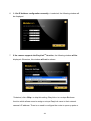
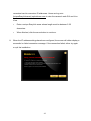
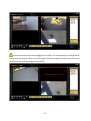
1
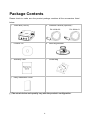
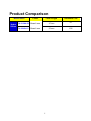
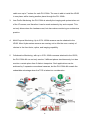
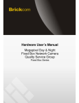
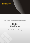
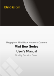
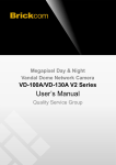
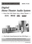
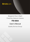
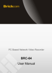
Hardware User’s Manual Hydra Series Megapixel Extendible Network Camera PH-100Ah Kit Series Product name: Network Camera (Hydra Series) Release Date: 2014/6 Manual Revision: V1.0 Web site: www.brickcom.com Email: [email protected] [email protected] © 2014 Brickcom Corporation. All Rights Reserved 0 Table of Contents Before You Use This Product ........................................................................................................... 2 FCC Warning ....................................................................................................................................... 3 Regulatory Information ...................................................................................................................... 4 Package Contents............................................................................................................................... 6 Product Comparison .......................................................................................................................... 7 Hydra Network Camera Overview.................................................................................................... 8 Device Appearance Description .................................................................................................... 10 LED Behavior..................................................................................................................................... 11 System Requirements...................................................................................................................... 13 Camera Installation .......................................................................................................................... 14 EasyConfig Installation ................................................................................................................... 17 Launch EasyConfig .......................................................................................................................... 21 Accessing the Network Camera..................................................................................................... 30 Viewing Video Streams with Internet Explorer ........................................................................... 31 Viewing Video Streams with BRC64 ............................................................................................. 31 1 Before You Use This Product In many countries, there are laws prohibiting or restricting the use of surveillance devices. This Network Camera is a high-performance, web-ready camera which can be part of a flexible surveillance system. It is the user’s responsibility to ensure that the operation of this camera is legal before installing this unit for its intended use. Upon opening the product’s package, verify that all the accessories listed on the “Package Contents” are included. Before installing the Network Camera, read the warnings in the “Quick Installation Guide” to avoid misuse. When installing the Network Camera, carefully read and follow the instructions in the “Installation” chapters to avoid damages due to faulty assembly or installation. 2 FCC Warning This device complies with Part 15 of FCC rules. Operation is subject to the following two conditions: (1) This device may not cause harmful interference. (2) This device must accept any interference received, including interference that may cause undesired operations. 3 Regulatory Information Federal Communication Commission Interference Statement This equipment has been tested and found to comply with the limits for a Class B digital device, pursuant to Part 15 of the FCC Rules. These limits are designed to provide reasonable protection against harmful interference in a residential installation. This equipment generates uses and can radiate radio frequency energy and, if not installed and used in accordance with the instructions, may cause harmful interference to radio communications. However, there is no guarantee that interference will not occur in a particular installation. If this equipment does cause harmful interference to radio or television reception, which can be determined by turning the equipment off and on, the user is encouraged to try to correct the interference by one of the following measures: Reorient or relocate the receiving antenna. Increase the separation between the equipment and receiver. Connect the equipment into an outlet on a circuit different from that to which the receiver is connected. Consult the dealer or an experienced radio/TV technician for help. FCC Caution: Any changes or modifications not expressly approved by the party responsible for compliance could void the user's authority to operate this equipment. This device complies with Part 15 of the FCC Rules. Operation is subject to the following two conditions: (1) This device may not cause harmful interference. (2)This device must accept any interference received, including interference that may cause undesired operation. 4 IMPORTANT NOTE: FCC Radiation Exposure Statement: This equipment complies with FCC radiation exposure limits set forth for an uncontrolled environment. This equipment should be installed and operated with minimum distance 20cm between the radiator & your body. This transmitter must not be co-located or operating in conjunction with any other antenna or transmitter. The availability of some specific channels and/or operational frequency bands are country dependent and are firmware programmed at the factory to match the intended destination. The firmware setting is not accessible by the end user. 5 Package Contents Please check to make sure the product package contains all the accessories listed below. a. Video Box (VB-03) b. Network Camera (Optional) * PH-100Ah-00 c. Product CD d. Mounting Bracket e. Warranty Card f. Screw Bag g. Easy Installation Guide PH-100Ah-01 (*) The actual device and quantity vary with the product’s configuration. 6 Product Comparison Model Name Hydra Series Lesns Focal Length Horizontal FOV PH-100Ah-00 Board Lens 3.7mm 57° Ph-100Ah-01 Board Lens 2.3mm 100° 7 Hydra Network Camera Overview Hydra series. As the name suggests, the product is capable of connecting up to 3 cameras with the transmission cables. The Hydra series is the world’s 1st simultaneous triple extensible view HDTV IP camera, offering the substantial advantage in the total cost of ownership (TCO), ease of use, and applicability. The debut of the Hydra series is another symbol for Brickcom’s commitment to driving innovation and bringing the best products to the market. The 1st product of the Hydra series is the PH-100Ah Kit. It consists of 1 unit of VB-03 video box and 1 unit of PH-100Ah super mini camera, and has the capability of connecting up to 3 PH-100Ah cameras. The PH-100Ah Kit reveals the following advantages and strengths: 1. Multiple Cameras on 1 Device: this is the key factor in reducing the cost of ownership (TCO). The idea is simple: the user can have 2 cameras for the cost of less than 2, and can have 3 cameras for the cost of less than 3. Furthermore, this triple-camera system runs merely on 1 IP address and 1 PoE cable. In addition to the reduced equipment cost, the user also benefits from the cost drops on the labor, time, and maintenance. 2. Extensible View: the PH-100Ah camera is a separate unit from the main body (VB-03), and is connected to the VB-03 via the extension cable. The extension 8 cable runs up to 7 meters for each PH-100Ah. The user is able to install the VB-03 in one place, while viewing another place through the PH-100Ah. 3. Low-Profile Monitoring: the PH-100Ah is actually the imaging sub-system taken out of the IP camera, and therefore it can be made extremely tiny and compact. This not only drives down the hardware cost, but also makes monitoring an unobtrusive practice. 4. Multi-Purpose Monitoring: Up to 3 PH-100Ah cameras can be attached to the VB-03. More Hydra series cameras are coming out to offer the user a variety of choices in the form factor, optics, and imaging capability. 5. Collaborative Monitoring: with up to 3 PH-100Ah cameras attached to the VB-03, the PH-100Ah Kit can not only monitor 3 different places simultaneously, but also monitor a certain place from 3 distinct viewpoints. Such applications can be achieved by 3 separate conventional cameras, but the PH-100Ah Kit reveals the unbeatable advantage when the TCO is taken into consideration. 9 Device Appearance Description < Front & Rear view > Audio out Audio in Status Internet Camera Connected indicator 1 Camera Connected indicator 2 Camera Connected indicator 3 3G dongle USB port Micro SD/SDHC/SDXC Card 2 pairs of DI/DO Camera Port 1 Camera Port 2 Camera Port 3 Power Jack (DC12V) Reset Button RJ45 connector (Ethernet/POE) PH-100Ah VB-03 10 LED Behavior Function LED Behavior Description Power Continuous Illumination Normal Operation Power Unlit Power off Status Continuous Illumination Connect to the switch by Ethernet or WiFi Status Unlit Status Blinking Data Transmission via Ethernet Internet Continuous Illumination Connect to Internet Internet Unlit Camera 1/2/3 Blinking Upgrading firmware Camera 1/2/3 Continuous Illumination Firmware is successfully upgraded 1. Power off 2. No connection 1. Power off 2. No Connection Hardware Reset Reset Button The Reset Button can be used to reboot the camera or restore it to the factory default settings. If the camera experiences a problem, rebooting the camera may fix the problem. If the problem remains, please restore the camera to the factory default settings and reinstall the software. To Reboot − Press and hold the Reset Button for one second using a paper clip or thin object. Wait for the camera to reboot. To Restore − Press and hold the Reset Button for ten seconds until the LED light turns off. When it is successfully restored, the LED will be blue during the normal 11 operation. NOTE - By restoring the camera, all settings will be restored to the factory default settings. Micro SD/SDHC/SDXC Card Capacity The network camera is compatible with Micro SD/SDHC/SDXC (Maximum 64GB) card. 12 System Requirements Operating System: Microsoft Windows, ONVIF Supported NVR system CPU: Pentium 3GHz or faster Network Interface: 10/100Mbps Network interface card must be installed Web Browser: Microsoft Internet Explorer, Firefox, Chrome Audio: The audio function will not work if a sound card is not installed in the PC. Audio may be interrupted depending on the network traffic. 13 Camera Installation Step 1. Power and Ethernet Connection a. Power on the camera with PoE switch: Use an Ethernet cable to connect VB-03 to the PoE switch. PoE Switch b. Power on the camera with PoE injector: i. Use an Ethernet cable to connect VB-03 to a PoE injector. ii. Use an Ethernet cable to connect the PoE injector to the non-PoE switch. iii. Connect the PoE injector to a power outlet. PoE Injector Router/ Computer/ NVR/ Switch 14 c. Power on the camera with DC12V 1A power adaptor. Router/ Computer/ NVR/ Switch Step 2. Terminal I/O Block Adaptor Pin Definition (from left to right) 1. Ground 2. 3. 4. 5. 6. Digital Input Digital Output Power +12V Ground Digital Input 7. Digital Output 8. Ground 15 Step 3. Camera Installation To extend the length of lens, we provide the 5-meter extension cable called “EXCB-5M” for you. Please click the following link to get more information about it if you need it. (http://www.brickcom.com/products/Accessory/index.php?series=Others#) Step 4. Check the Lens Module Connections and LED Indicators Please make sure you have plugged in all the needed lens modules to the VB-03, and make sure the corresponding LED indicators are lit. The Hydra series camera offers simultaneous dual views with 2 lens modules connected, and simultaneous triple views with 3 lens modules connected. 16 EasyConfig Installation 1. Insert the Installation CD into the CD-ROM driver. Run Auto-Run Tool directly from the CD-ROM to start the installation. When installing the Brickcom software kit at the first time, select a desired language for the interface. The available languages are listed in the scroll box. Click <Install EasyConfig> and follow the steps to install the EasyConfig wizard on the desired computer. 17 2. In the Install Shield Wizard dialog box, click <Next> to continue. 3. Read the End-User License Agreement and check the option <I accept the terms of the license agreement>. Then, click <Next> to continue. 18 4. Click <Change> to change the appointed folder where the installation and program files will be stored. Then, click <Next> to continue. 5. Select to create shortcuts and click <Next> to continue. 19 6. Click to launch the application, and click <Finish> to complete the installation and return to Shield Wizard dialog box. When launching the PC-NVR program, please refer to the PC-NVR’s user manual. 20 Launch EasyConfig Users can search cameras by EasyConfig and configure the settings below: IP address configuration Easylink configuration Live View & Individual Camera Modification BRC64 To launch EasyConfig, select “EasyConfig” from the start menu. If Complete Setup type was used in the software installation, an EasyConfig icon was installed on the desktop. Double click to launch EasyConfig. If Custom Setup type was used in the software installation but an EasyConfig icon was not installed on the desktop, the program will be installed under “C:\Program Files\Brickcom\EasyConfig” unless the program was saved to a preferred directory. NOTE - Check <Skip the hardware installation guide> to skip checking the hardware connection. To check the hardware installation settings, do not check the option box. 21 1. Click <Start> to continue. The program will automatically search for the camera in the intranet. 22 23 2. Select either <Simple Mode> or <Professional Mode> to obtain the camera’s IP settings. If <Simple Mode> is selected, EasyConfig will set up the connection automatically. If <Professional Mode> is selected, the user will need to configure the IP settings manually. 3. There may be many cameras in the local network. Differentiate the cameras using their UPnP name. Double click on the camera from the survey list to connect. 24 4. Enter the username and password of the camera. For the first-time use, the default username and password are “admin/admin.” 5. To configure the IP address settings, select either <Settings remain the same>, <Automatically obtain an IP Address (DHCP)> or <Set IP Address configuration manually>. The DHCP setting is recommended. 25 6. If <Set IP Address configuration manually> is selected, the following window will be displayed. 7. If the camera supports the EasyLinkTM function, the following window will be displayed. Otherwise, this window will not be shown. *If desired, click <Skip> to skip this setting. EasyLinkTM is a unique Brickcom function which allows users to assign a unique EasyLink name to their network camera’s IP address. There is no need to configure the router to open up ports or 26 remember hard-to-memorize IP addresses. Users can log onto [uniqueEasyLinkname].mybrickcom.com to view the camera’s web GUI and Live View. Enter a unique EasyLink name whose length must be between 5-32 characters. 8. When finished, click the arrow button to continue. When the IP address settings have been configured, the screen will either display a successful or failed connection message. If the connection failed, either try again or quit the installation. 27 If “DHCP IP address settings” was selected, the failure window will be displayed as below. If <Static IP address settings> was selected, the failure window will be displayed as above. If the connection was successful, the user will see the message: <Congratulations. The installation of the camera is complete.> 28 9. When this window is displayed, click <BRC64> to start the BRC64 program, <Live View> to view the live video from the connected IP camera, or <X> in the top right corner of the screen to close the installation window. If the user starts the BRC64 program, please refer to PC-NVR’s user manual. Once the installation is complete, the administrator should proceed to the next section "Accessing the Network Camera" for necessary changes and configurations. 29 Accessing the Network Camera Check Network Settings The camera can be connected either before or immediately after the software installation. The Administrator should complete the network settings on the configuration page, including entering the correct subnet mask, IP address of gateway, and DNS. Ask the network administrator or Internet service provider for the detail information. Add the Password to Prevent Unauthorized Access The administrator should immediately implement a new password as a matter of prudent security practice. For the first time, the username and password for the administrator are assigned as “admin/admin”. After the administrator changes the administrator password, the web browser will display an authentication window to confirm the new password. Once the password is set, there is no provision to recover the administrator’s password. If the administrator’s password is lost, please reset to the original factory default settings. The administrator can be set up a maximum of ten user accounts. Users will be able to access the network camera, but will not be allowed to access system configurations. 30 Viewing Video Streams with Internet Explorer Step 1. Check the Video Stream Settings On the camera's web UI, please go to Configuration → Camera/Video/Audio → Video, and you will find the stream 1, stream 2, and stream 3 settings. Please make sure the video stream corresponding to the connected lens module is enabled. (Stream 1 corresponds to the lens module connected to lens port 1, and so on.) Step 2. Select the Video Stream for Live View After finishing the video stream settings, please go to “Live View” and select the stream you want to view from Channels (Stream1 / Stream2 / Stream3). 31 Viewing Video Streams with BRC64 Step 1. Launch BRC64 Double click on the Windows desktop to launch BRC64, or click it on the program menu. ○i Please make sure the version of BRC64 is v1.2.4.144 or above. Step 2. Search for the Camera Click on the control panel to start searching for the cameras on the LAN. No matter how many lens modules you plug in the VB-03, three camera items will be displayed with the same name on the control panel. 32 Step 3. View 3 Streams Simultaneously For each video stream you want to view, please select the camera item on the control panel. Then, drag and drop it to the video matrix for live view. 33 If the lens module hasn’t been pluggged in the VB-03, the “Reconnecting” message will be shown, and you won’t be able to view the image of this lens module. Please check if the lens modules are successfully plugged in the VB-03. 34