1
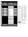
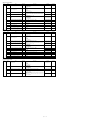
Output Setting
Menu
OUT
Symbol
OT
Name
Output type selection
Display level
EASY
Setting range
Initial value
Control output or Heating-side control output (Lower two digits)
00: OFF
01: OUT terminals (voltage pulse)
02: OUT terminals (current)
03: OUT terminals (relay/triac)
04: OUT2 terminals (voltage pulse)
05: OUT2 terminals (current)
06: OUT2 terminals (relay/triac)
Cooling-side control output (Upper two digits)
00: OFF
01: OUT terminals (voltage pulse)
02: OUT terminals (current)
03: OUT terminals (relay/triac)
04: OUT2 terminals (voltage pulse)
05: OUT2 terminals (current)
06: OUT2 terminals (relay/triac)
Standard type: 00.03
Heating/cooling type: 06.03
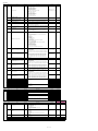
CTc
Control output cycle time
Heating-side control output cycle time (in
Heating/cooling control)
Cooling-side control output cycle time
V.AT
Automatic valve position adjustment
EASY
OFF: Stop automatic adjustment
ON: Start automatic adjustment
OFF
V.RS
Valve position setting reset
EASY
Setting V.RS to ON resets the valve adjustment settings and causes the
indication “V.RS” to blink.
OFF
CT
EASY
Fully-closed valve position setting
V.H
Fully-open valve position setting
EASY
TR.T
Valve traveling time
STD
V.MOD
Valve adjusting mode
STD
RTS
Retransmission output type of RET
30.0 s
0.5 to 1000.0 s
EASY
V.L
EASY
EASY
User setting
30.0 s
Pressing the SET/ENTER key with valve position set to the fullyclosed position
by Down arrow key causes the adjusted value to be stored. When V.L
adjustment is complete, V.L stops blinking.
Pressing the SET/ENTER key with valve position set to the fullyopened position
by Up arrow key causes the adjusted value to be stored. When V.H adjustment is complete, V.H stops blinking.
5 to 300 s
60 s
0: Valve position feedback type
1: Valve position feedback type
(moves to the estimating type if a feedback input error or break occurs.)
2: Valve position estimating type
0
OFF: Disable
PV1: PV
SP1: SP
OUT1: OUT (Valve opening: 0 to 100 % in Position proportional control)
LPS: 15 V DC loop power supply
PV2: Loop-2 PV
SP2: Loop-2 SP
OUT2: Loop-2 OUT
TSP1: Target SP
HOUT1: Heating-side OUT
COUT1: Cooling-side OUT
MV1: Position proportional output internal computed value)
TSP2: Loop-2 target SP
HOUT2: Loop-2 heating-side OUT
COUT2: Loop-2 cooling-side OUT
MV2: Loop-2 position proportional output (internal computed value)
PV: PV terminals analog input
RSP: RSP terminals analog input
AIN2: AIN2 terminals analog input
AIN4: AIN4 terminals analog input
PV1
Loop-2 setting values are unavailable in Single-loop control.
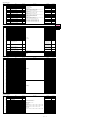
RTH
Maximum value of retransmission output scale
of RET
STD
RTL
Minimum value of retransmission output scale
of RET
STD
O1RS
Retransmission output type of OUT current
output
STD
O1RH
Maximum value of retransmission output scale
of OUT current output
STD
O1RL
Minimum value of retransmission output scale
of OUT current output
STD
O2RS
Retransmission output type of OUT2 current
output
STD
O2RH
Maximum value of retransmission output scale
of OUT2 current output
STD
O2RL
Minimum value of retransmission output scale
of OUT2 current output
STD
OU.H
100% segmental point of OUT current output
PRO
OU.L
0% segmental point of OUT current output
PRO
OU2.H
100% segmental point of OUT2 current output
PRO
OU2.L
0% segmental point of OUT2 current output
PRO
RET.H
100% segmental point of RET current output
PRO
RET.L
0% segmental point of RET current output
PRO
OU.A
OUT current output range
STD
OU2.A
OUT2 current output range
STD
RET.A
RET current output range
STD
When RTS = PV1, SP1, PV2, SP2, TSP1, TSP2, PV, RSP, AIN2, or AIN4,
RTL + 1 digit to 30000
-19999 to RTH - 1 digit
Decimal point position:
When RTS=PV1, SP1, or TSP1, decimal point position is same as that of PV
input.
When RTS=PV2, SP2, or TSP2, decimal point position is same as that of RSP
input.
When RTS=PV, decimal point position is same as that of PV input scale.
When RTS=RSP, decimal point position is same as that of RSP input scale.
When RTS=AIN2, decimal point position is same as that of AIN2 scale.
When RTS=AIN4, decimal point position is same as that of AIN4 scale.
Same as RTS
100 % of PV input range
0 % of PV input range
OFF
When O1RS = PV1, SP1, PV2, SP2, TSP1, TSP2, PV, RSP, AIN2, or AIN4,
O1RL + 1 digit to 30000
-19999 to O1RH - 1 digit
Decimal point position:
When O1RS=PV1, SP1, or TSP1, decimal point position is same as that of PV
input.
When O1RS =PV2, SP2, or TSP2, decimal point position is same as that of RSP
input.
When O1RS =PV, decimal point position is same as that of PV input scale.
When O1RS =RSP, decimal point position is same as that of RSP input scale.
When O1RS =AIN2, decimal point position is same as that of AIN2 scale.
When O1RS =AIN4, decimal point position is same as that of AIN4 scale.
Same as RTS
OFF
When O2RS = PV1, SP1, PV2, SP2, TSP1, TSP2, PV, RSP, AIN2, or AIN4,
O2RL + 1 digit to 30000
-19999 to O2RH - 1 digit
Decimal point position:
When O2RS=PV1, SP1, or TSP1, decimal point position is same as that of PV
input.
When O2RS =PV2, SP2, or TSP2, decimal point position is same as that of RSP
input.
When O2RS =PV, decimal point position is same as that of PV input scale.
When O2RS =RSP, decimal point position is same as that of RSP input scale.
When O2RS =AIN2, decimal point position is same as that of AIN2 scale.
When O2RS =AIN4, decimal point position is same as that of AIN4 scale.
100.0%
0.0%
100.0%
-100.0 to 200.0%
0.0%
100.0%
0.0%
4-20:
0-20:
20-4:
20-0:
4 to 20
0 to 20
20 to 4
20 to 0
4-20
mA
mA
mA
mA
4-20
4-20
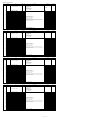
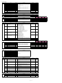
Heater Break Alarm Setting
Menu
HBA
Symbol
Name
Display level
HB1.S
Heater break alarm-1 function selection
EASY
HB2.S
Heater break alarm-2 function selection
EASY
HB1
Heater break alarm-1 current setpoint
EASY
HB2
Heater break alarm-2 current setpoint
EASY
CT1.T
CT1 coil winding number ratio
EASY
CT2.T
CT2 coil winding number ratio
EASY
HDN1
Heater break alarm-1 Ondelay timer
STD
HDN2
Heater break alarm-2 Ondelay timer
STD
HDF1
Heater break alarm-1 Offdelay timer
PRO
HDF2
Heater break alarm-2 Offdelay timer
PRO
HB1.D
Heater break alarm-1 contact type
PRO
HB2.D
Heater break alarm-2 contact type
PRO
Setting range
Initial value
1
OFF
OFF, 0.1 to 300.0 Arms
OFF
800
1 to 3300
800
0.00
0.00
0.00 to 99.59 (minute.second)
0.00
0.00
CLS: When the event occurs, the contact is closed.
OPN: When the event occurs, the contact is opened.
CLS
CLS
RS-485 Communication Setting
Menu
R485
Symbol
Name
User setting
1
0: Heater current measurement
1: Heater break alarm
Display level
Setting range
Initial value
PSL
Protocol selection
EASY
BPS
Baud rate
EASY
PRI
Parity
EASY
STP
Stop bit
EASY
PCL: PC link communication
PCLSM: PC link communication (with checksum)
LADR: Ladder communication
CO-M: Coordinated master station
MBASC: Modbus (ASCII)
MBRTU: Modbus (RTU)
CO-S2: Coordinated slave station (Loop-2 mode)
P-P: Peer-to-peer communication
600: 600 bps
1200: 1200 bps
2400: 2400 bps
4800: 4800 bps
9600: 9600 bps
19200: 19.2k bps
38400: 38.4k bps (except for communication of E4 terminal area)
NONE: None
EVEN: Even
ODD: Odd
1: 1 bit, 2: 2 bits
DLN
Data length
EASY
7: 7 bits, 8: 8 bits
8
ADR
Address
EASY
1 to 99
1
RP.T
Minimum response time
PRO
0 to 10 (x10ms)
0
MBRTU
19200
EVEN
1
Page 18 / 25
(E3 terminal
area)
(E4 terminal
area)
User setting
User setting