1
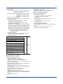
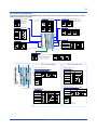
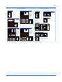
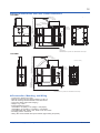
UT55A/MDL, UT52A/MDL
Controllers
General
Specifications
l
tiona
Func ment
nce
Enha
(Mount on DIN Rail)
GS 05P01C81-01EN
nOverview
The UT55A/MDL and UT52A/MDL controllers can be
mounted in a panel. A ladder sequence function is
included as standard. The short depth of the controller helps save instrument panel space. The UT55A/
UT52A also support open networks such as Ethernet
communication.
nFeatures
•Simple panel surface
Mounting the controller in a panel simplifies the panel
surface.
•Ladder sequence function is included as standard.
This function allows for creating a simple sequence
control. Dedicated LL50A Parameter Setting Software
(sold separatly) allows for performing programming
using a ladder language.
•Various built-in open network functions such as Ethernet are available.
Easy connection with various vendors’ PLCs is possible.
(UT52A support CC-Link and RS485 communication
only.)
•Equipped with a multitude of functions
Universal I/O, eight control modes (cascade control, etc), and retransmission output are included as
standard. PID control, heating/cooling control, feed
forward control, etc. are available.
•LL50A Parameter Setting Software (sold separately)
The parameters and ladder programs of UTAdvanced
controller can be built from a PC using this software.
It makes data management even easier.
nFunctional Specifications
(1) Control Mode
Control functions of the controller can be set as control
modes.
*1:
Function
Single-loop control
Cascade primary-loop control (*1)
Cascade secondary-loop control (*1)
Cascade control (*1)
Loop control for backup (*1)
Loop control with PV switching (*1)
Loop control with PV auto-selector (Max./Min./Ave./Diff.) (*1)
Control with PV-hold function
Remote auxiliary analog input is required.
2) Control period
Selectable from 50 ms (*2), 100 ms, and 200 ms
*2:
UT52A/MDL
Table of Number of Inputs and Outputs
Model and
suffix code
(See the
model code)
Number
of analog
input
points
Number
of analog
output
points (*3)
Number
of contact
input
points (*4)
Number of
contact
output
points (*5)
-×0×/MDL
-×2×/MDL
-×3×/MDL
-×4×/MDL
-×5×/MDL
-×7×/MDL
1
2
1
2
2
4
1
1
1
1
1
1
3
4
8
3
9 (8)
6 (5)
3
3
8
3
8
3
-×0×/MDL
-×1×/MDL
1
2
1
1
3
4 (3)
3
3
UT55A
UT52A
*3:
*4:
*5:
Excluding control output
The numbers in parentheses show the numbers of
points in each model with RSP direct input. (/DR
option.
Excluding control output relays
Control Computation Specifications
Control Specifications
Control mode
SGL (1)
CAS1 (2)
CAS2 (3)
CAS (4)
BUM (5)
PVSW (6)
PVSEL (7)
PVHD (8)
UT55A/MDL
Cascade control (Control mode 4) cannot be used.
“Super” function or “Super 2” function cannot be used.
(1) Combination of types of control and control modes
Types of control
PID control
ON/OFF control
Two-position, two-level
control (*6)
Heating and cooling
control (*6)
Sample PI control
Batch PID control
Feedforward control
√:
*6:
N/A
Control mode
3 4 5 6
√ √ √ √
N/A N/A N/A √
7
√
√
N/A
√
N/A
N/A
√
N/A
√
√
√
√
N/A
N/A
N/A
N/A
N/A
N/A
1
√
√
2
√
N/A
8
√
N/A
N/A
N/A
N/A
√
√
√
√
√
N/A
N/A
N/A
N/A
N/A
N/A
√
√
√
√
√
√
√
N/A
N/A
Available N/A: Not Available
Selectable for heating and cooling control
(2) Control Computation Function
(a) Target setting point and the number of PID parameter groups
Respectively, eight sets of target setpoints, alarm setpoints, and PID parameters can be set. For cascade
control, respectively, eight sets can be set for main
(primary side) and slave (secondary side).
Yokogawa Electric Corporation
2-9-32, Nakacho, Musashino-shi, Tokyo, 180-8750 Japan
Tel.: 81-422-52-7179 Fax.: 81-422-52-6619
GS 05P01C81-01EN
1st Edition Mar.31, 2015 (YK)
2
(b) Selecting the PID parameter group
The following PID parameter groups can be selected.
•Target setpoint number (SPNO) (The PID number
can be set arbitrarily.)
•Measured input zone PID
•Target setpoint zone PID
•Reached target setpoint zone PID
(c) Auto-tuning
•Tuning results can be selected from two options,
Normal or Stable.
•Tuning output limit can be set. (It cannot be used in
heating/cooling control.)
(d) “Super” function: Overshoot-suppressing function
(e) “Super 2” function: Hunting-suppressing function
(f) STOP preset output function
(g) Input ERROR preset output function
(h) MANUAL preset output function
Contact I/O Function
This function allows for allocating the input error
condition, operation condition, alarm condition or other
conditions to the contact input and contact output.
Contact input
(3) Operation Mode Switching
Operation mode
switching
AUTO/MANUAL and RUN/STOP switching
CASCADE/AUTO/MANUAL switching
REMOTE/LOCAL switching
Contact output
(4) Control Parameter Setting Range
Proportional band
Integral time
Derivative time
ON/OFF control
hysteresis (one or two
hysteresis points)
Preset output
value
High/low output
limiter
Tight shut
function
Rate-of-change
limiter of output
Output deadband
0.1 to 999.9%
1 to 6000 sec. or OFF (using manual reset)
1 to 6000 sec. or OFF
0.0 to 100.0% of measured input range width
-5.0 to 105.0% (however, 0 mA or less cannot
be output)
-5.0 to 105.0%
Low limit setpoint < high limit setpoint
When manual control is carried out with 4 to
20 mA output, control output can be reduced to
about 0 mA.
0.1 to 100.0%/sec., OFF
For heating and cooling control: -100.0 to 50.0%
(5) Ladder computation period
Ladder computation period is the same as control period.
Alarm Functions
•Types of Alarm
Measured value
alarm
Deviation alarm
Rate-of-change
alarm
Setpoint alarm
Output alarm
Other alarms
PV (measured value) high/low limit alarm
Deviation high/low limit alarm
Deviation high and low limits alarm
Deviation within high and low limits alarm
Analog input PV high/low limit alarm
Analog input RSP (ROMOTE) SP high/low limit alarm
Auxiliary analog input high/low limit alarm
PV rate-of-change alarm
SP (setpoint) high/low limit alarm
Target SP high/low limit alarm
Target SP deviation high/low limit alarm
Target SP deviation high and low limits alarm
Target SP deviation within high and low limits alarm
Control output high/low limit alarm
Cooling control output high/low limit alarm
Self-diagnosis alarm
FAIL
•Alarm Functions
Alarm output
action
Number of alarm
settings
Number of alarm
output points
AUTO/MANUAL switching
REMOTE/LOCAL switching
STOP/START switching
Switching to CASCADE
Switching to AUTO
Switching to MANUAL
Switching to REMOTE
Switching to LOCAL
AUTO-TUNING START/STOP switching
OUTPUT TRACKING switching
Two-input switching
PV Hold
SP number specification
PID number specification
Manual preset output number specification
Loop 1 alarms 1 through 8
Loop 2 alarms 1 through 8 (for cascade control)
Status output
Ladder Sequence Function
(1) Number of I/O Points
Number of digital input points
Number of digital output points
UT55A/MDL
Up to 9
Up to 18
UT52A/MDL
Up to 4
Up to 3
This is limited by the number of contact I/O signal
points. (See the model code.)
(2) Types of Command
Number of basic
command types
Number of
commands
13
Number of application command types
73
Remark
Load, AND, OR, Timer,
Counter, etc.
Comparison, reverse, addition/
subtraction/multiplication/
division, logic operation, high/
low limiter, etc.
(3) Sequence Device
Digital I/O
Internal device
Special device
*
Types of device
Input relay
Output relay
M relay (bit data)
DAT register (data)
P register (parameter)
K register (constant)
Special relay (bit data)
Number of points
9 (max)
8 (max)
256
28
10
30
12
Process data and process relay can be used besides
the above-mentioned.
(4) Program capacity
Max. Program capacity: 500 steps *
*:
Available number of steps differs according to the
parameters, using command and control period.
(5) Ladder computation period
Ladder computation period is the same as control
period.
Alarm stand-by action
Alarm latch (forced reset) function
Alarm hysteresis
Alarm ON/OFF delay timer
8 (per loop)
Up to 8 (differs by model code)
All Rights Reserved. Copyright © 2015, Yokogawa Electric Corporation
GS 05P01C81-01EN
Mar.31, 2015-00
3
Communication Function
Function
Modbus/TCP
Modbus
(RTU/ASCII)
A standard industry protocol
allowing communications
between the controller and
devices such as PCs, PLCs,
and DCSs.
PROFIBUSDP
Used for communication
between PLCs and
remote I/O, enabling highspeed data transmission.
CC-Link
DeviceNet
Method
Interface
Targets
Max connection
Server
Ethernet
2 connections
Gateway
Ethernet
+RS-485
Slave
RS-485
PLC and others
RS-485: UT75A/
UT55A/UT52A/UT35A/
UT32A/UP55A/UP35A/
UM33A (*1)
PLC and others,
UT75A/UT55A/UT52A/
UT35A/UT32A/UP55A/
UP35A/UP32A/
UM33A(*2)
Slave
RS-485
PLC and others
Modbus master
function
RS-485
UT75A/UT55A/UT52A/
UT35A/UT32A/UP55A/
UP35A
Slave
RS-485
PLC and others
Modbus master
function
RS-485
UT75A/UT55A/UT52A/
UT35A/UT32A/UP55A/
UP35A/UP32A/UM33A
Slave
RS-485
PLC and others
Modbus master
function
RS-485
UT75A/UT55A/UT52A/
UT35A/UT32A/UP55A/
UP35A
Communication
Data
31 units
31 units
Number of nodes:
126
31 Units
(Main Controller
is included.)
Number of nodes:
42 (Remote device)
31 Units
(Main Controller
PV, SP, OUT,
is included.)
ALM etc
Number of nodes:
64
31 Units
(Main Controller
is included.)
A protocol allowing multiple
Read/Write: 4
controllers to send and
RS-485 UT75A/UT55A/UT52A/
units
Peer to peer
receive data between
Multi-drop
(2 wire
UT35A/UT32A/UP55A/
Read only : 28
one another. The Ladder
only)
UP35A/UP32A
units
Program is used.
A
protocol
to
coordinate
the
Coordinated
UT75A/UT55A/UT52A/
of two or more
Master : 1 unit
Communica- operation
Master/Slave
RS-485 UT35A/UT32A/UP55A/
instruments controlling the
Slave : 31 units
(*2)
UP35A/UP32A
tion
same process.
The proprietary Yokogawa
PC and others,
protocol allowing
PC link
UT75A/UT55A/UT52A/
communications to PCs,
Slave
RS-485 UT35A/UT32A/UP55A/
31units
PLCs and touch panels.
UP35A/UP32A/
A
protocol
to
communicate
UM33A(*2)
Ladder
to PLCs.
*1: UT digital indicating controller, Signal conditioner JUXTA, Power monitor POWERCERT can be connected.
*2: UT digital indication controllers can be connected.
Physical Interface
Ethernet
Standard : IEEE802.3 (10BASE-T, 100BASE-TX)
Max segment length : 100m
Max. Connecting Configguration : Cascade Max. 4 level (10BASE-T), Max. 2 level (100BASE-TX)
RS-485
Standard : EIA RS-485
Communication method : Two-wire harf-duplex or four-wire harf-duplex, start-stop synchoronization
and non-procedural
Baud rate : 600, 1200, 2400, 4800, 9600, 19200 or 38400bps (*3), Peer to peer communication is fixed at
19200bps
Maximum communication distance : 1200m
Terminating resistor : 220Ω (External)
*3:
“38400 bps” is available only for UT55A (Type 3 code = 1) and UT52A (Type 2 code = 1)
*4:
AUTO automatically sets the baud rate to that of the host controller (PROFIBUS-DP master).
PROFIBUS-DP Standard : Field bus (IEC61158)
Corresponding version : DP V0
Baud rate : 9.6k, 19.2k, 45.45k, 93.75k, 187.5k, 0.5M, 1.5M, 3M, 6M, 12M, AUTO (*4)
Communication distance :1200m (9.6k to 93.75k)
1000m (187.5k)
400m (0.5M)
200m (1.5M)
100m (3M to 12M)
CC-LinkSupported version : Remote device (Ver.1.10, Ver.2.00)
Baud rate : 156k, 625k, 2.5M, 5M, 10M bps
Transmission distance : 1.2km (156k bps), 600m (625k bps), 200m (2.5M bps), 150m (5M bps),
100m (10M bps)
When using optical repeater : 7.6 km (156k) to 4.3 km (10M)
DeviceNet
Field bus (IEC61158)
Baud rate: 125k, 250k, 500k bps
Transmission distance: 500m (125k bps), 250m (250k bps), 100m (500k bps)
All Rights Reserved. Copyright © 2015, Yokogawa Electric Corporation
GS 05P01C81-01EN
Mar.31, 2015-00
4
nHardware Specifications
Universal Input Specifications
Display Specifications
The controller status can be verified with the LED.
Status
Normal
Communication
error
LED
Green
Lit/Blinks
Lit
Green
Blinks
Instrument failure
Red
Lit
Input error
Red
Blinks
Description
•Number of input points: 1
•Types of input, instrument range, and measurement
accuracy (see the table below)
Types of input
K
Parameter error/
Hardware failure/Ladder
program corruption.
sensor burnout, input
over
J
T
Thermocouple
LED lamp
UT55A/MDL Front
(with terminal cover)
UT52A/MDL Front
(with terminal cover)
0.0 to 400.0°C
-200.0 to 750.0°F
B
0.0 to 1800.0°C
32 to 3300°F
S
R
0.0 to 1700.0°C
0.0 to 1700.0°C
32 to 3100°F
32 to 3100°F
N
-200.0 to 1300.0°C
-300.0 to 2400.0°F
E
L
-270.0 to 1000.0°C
-200.0 to 900.0°C
-200.0 to 400.0°C
-450.0 to 1800.0°F
-300.0 to 1600.0°F
-300.0 to 750.0°F
0.0 to 400.0°C
-200.0 to 1000.0°F
0.0 to 2300.0°C
32 to 4200°F
U
W (*2)
Resistance-temperature
detector (RTD) 3-wire
Instrument range
°C
°F
-270.0 to 1370.0°C -450.0 to 2500.0°F
-270.0 to 1000.0°C -450.0 to 2300.0°F
-200.0 to 500.0°C
-200.0 to 1000.0°F
-200.0 to 1200.0°C -300.0 to 2300.0°F
-270.0 to 400.0°C
-450.0 to 750.0°F
Platinel
0.0 to 1390.0°C
2
32.0 to 2500.0°F
PR20-40 0.0 to 1900.0°C
32 to 3400°F
W97
Re3-W75 0.0 to 2000.0°C
Re25
32 to 3600°F
JPt100
-200.0 to 500.0°C
-150.00 to 150.00°C -200.0 to 300.0°F
-200.0 to 850.0°C
-200.0 to 500.0°C
Pt100
Standard
signal
DC voltage
DC current
-300.0 to 1000.0°F
-300.0 to 1560.0°F
-300.0 to 1000.0°F
Accuracy
±0.1% of instrument
range ±1 digit for 0°C
or more
±0.2% of instrument
range ±1 digit for less
than 0°C
However, ±2% of
instrument range
±1 digit for less than
-200°C of thermocouple
K ±1% of instrument
range ±1 digit for less
than -200°C of thermocouple T
±0.15% of instrument
range ±1 digit for 400°C
or more
±5% of instrument
range ±1 digit for less
than 400°C
±0.15% of instrument
range ±1 digit
±0.1% of instrument
range ±1 digit
±0.25% of instrument
range ±1 digit for less
than 0°C
±0.1% of instrument
range ±1 digit for 0°C
or more
±0.2% of instrument
range ±1 digit for less
than 0°C
However, ±1.5% of
instrument range ±1 digit
for less than -200.0°C of
thermocouple E
±0.2% of instrument
range ±1 digit
±0.1% of instrument
range ±1 digit
±0.5% of instrument
range ±1 digit for 800°C
or more
Accuracy not guaranteed for less than 800°C
±0.2% of instrument
range ±1 digit
±0.1% of instrument
range ±1 digit (*1)
±0.1% of instrument
range ±1 digit
±0.1% of instrument
range ±1 digit (*1)
-150.00 to 150.00°C -200.0 to 300.0°F
±0.1% of instrument
range ±1 digit
0.400 to 2.0000 V
1.000 to 5.000 V
4.00 to 20.00 mA
0.000 to 2.000 V
0.00 to 10.00 V
-10.00 to 20.00 mV
0.00 to 20.00 mA
±0.1% of instrument
range ±1 digit
-
The accuracy is that in the standard operating conditions: 23 ±2°C, 55 ±10%RH, and power frequency at
50/60 Hz.
*1:
*2:
±0.3°C and ±1 digit in the range between 0 and 100°C
±0.5°C ±1 digit in the range between -100 and 200°C
W-5% Re/W-26% Re (Hoskins Mfg.Co.), ASTM E988
•Applicable standards: JIS, IEC and DIN (ITS-90) for thermocouples and resistance-temperature detectors (RTD)
•Input sampling period: Synchronized to control period
All Rights Reserved. Copyright © 2015, Yokogawa Electric Corporation
GS 05P01C81-01EN
Mar.31, 2015-00
5
•Burnout detection
Upscale and downscale of function, and OFF can
be specified for the standard signal of thermocouple and resistance-temperature detector (RTD).
For integrated signal input, 0.1 V or 0.4 mA or less
is judged as a burnout.
•Input bias current: 0.05 μA (for thermocouple and
resistance-temperature detector (RTD))
•Resistance-temperature detector (RTD) measured
current: About 0.16 mA
•Input resistance
1 MΩ or more for thermocouple/mV input
About 1 MΩ for voltage input
About 250 Ω for current input (with built-in shunt
resistance)
•Allowable signal source resistance
250 Ω or less for thermocouple/mV input
Effect of signal source resistance: 0.1 μV/Ω or less
2 kΩ or less for DC voltage input
Effect of signal source resistance: about
0.01%/100 Ω
•Allowable wiring resistance
Up to 150 Ω per line for resistance-temperature
detector (RTD) input (conductor resistance
between the three lines shall be equal)
Effect of wiring resistance: ±0.1°C/10 Ω
•Allowable input voltage/current
±10 V DC for thermocouple/mV/mA or resistance temperature detector (RTD) input
±20 V DC for V input
±40 mA DC for mA input
•Noise reduction ratio
40 dB or more (at 50/60 Hz) in normal mode
120 dB or more (at 50/60 Hz) in common mode
•Reference junction compensation error
±1.0°C (15 to 35°C)
±1.5°C (-10 to 5°C and 35 to 50°C)
Auxiliary Analog Input Specifications
•This function can be used for remote setpoint setting,
external compensating input, auxiliary input for computation, etc.
•Number of input points: see the model code table.
•For types of input, instrument range, and measurement accuracy, see the table below.
Types of input
Integrated signal
DC voltage
DC voltage with High
input impedance
Instrument range
Accuracy
0.400 to 2.000 V
±0.2% of instrument range ±1 digit
1.000 to 5.000 V
±0.1% of instrument range ±1 digit
0.000 to 2.000 V
±0.2% of instrument range ±1 digit
0.00 to 10.00 V
±0.1% of instrument range ±1 digit
0.000 to 1.250 V
±0.1% of instrument range ±1 digit
•Input sampling period: Synchronized to control period
•Input resistance: about 1 MΩ
However, 10 MΩ or more for high input impedance
•Burnout detection: Functions at standard signal
Burnout is determined to have occurred if it is
0.1 V or less.
Contact Input Specifications
•Number of points: 3 points (standard)
For the maximum number of points, see the
model and suffix code table.
•Input type: no-voltage contact input or transistor contact input
All Rights Reserved. Copyright © 2015, Yokogawa Electric Corporation
•Input contact capacity: 12 V DC, 10 mA or more
Be sure to use a contact with a minimum ON
current of 1 mA or more
•ON/OFF detection
For no-voltage contact input:
Contact resistance 1 kΩ or less in ON state
Contact resistance 50 kΩ or more in OFF state
Transistor contact input:
2 V or less in ON state
Leak current 100 μ A or less in OFF state
•Status detection minimum hold time: control period
+ 50 ms
•Application: SP switching, operation mode switching,
event input
Analog Output Specifications
•Number of points
Control output (heating-side output): 1 point
(standard), which is shared with transmission
output
Cooling-side output: 1 point, which is
shared with transmission output
•Output functions
Current output or voltage pulse output
•Current output
4 to 20 mA DC or 0 to 20 mA DC/load resistance
600 Ω or less
•Current output accuracy
±0.1% of span (however, ±5% of span for 1 mA
or less)
The accuracy is that in the standard operating
conditions: 23 ±2°C, 55 ±10%RH, and power
frequency at 50/60 Hz
•Voltage pulse output
Application: time proportional output
ON voltage: 12 V or more/load resistance of 600 Ω or more
OFF voltage: 0.1 V DC or less
Time resolution: 10 ms or 0.1% of output value,
whichever is larger
Retransmission Output Specifications
•Number of points: 1 point (standard), which is shared
with 15 V DC loop power supply
Additional 2 points when analog control output and
cooling-side analog control output are not used
•Output function: current output
4 to 20 mA DC or 0 to 20 mA DC/load
resistance 600 Ω or less
•Current output accuracy (conversion accuracy from
PV value on the set scale): ±0.1% of span (however,
±5% of span for 1 mA or less)
The accuracy is that in the basic operating
conditions: 23 ±2°C, 55 ±10%RH, and power
frequency at 50/60 Hz
This is not conversion accuracy through input
and output but the performance of transmission
output itself.
15V DC Loop Power Supply Specifications
•Number of points: 1 point (standard), which is shared
with retransmission output
Control output (1 point) can also be used.
•Supply voltage: 14.5 to 18.0 V DC
•Maximum supply current: about 21 mA (with shortcircuit current limiting circuit)
GS 05P01C81-01EN
Mar.31, 2015-00
6
Step Response Time Specifications
Within 500 ms (for a control period of 50 ms or 100 ms)
Within 1 s (for a control period of 200 ms)
(Response time at 63% of transmission output when a
change is made stepwise in the range between 10 and
90% of input span)
Relay Contact Output Specifications
•Types of contact and number of points
Control relay output: one 1c-contact point
Cooling output of heating and cooling control:
one 1c-contact point (For UT55A/MDL only)
For UT52A/MDL heating/cooling output: 2,
1a-contact points
Alarm output: 3 1a-contact points (Common is separated)
•Contact rating
1c-contact: 3 A at 250 V AC or 3 A at 30 V DC
(resistance load)
1a-contact:
For alarm output: 1 A at 240 V AC or 1 A at
30 V DC (resistance load)
For UT52A/MDL control relay output: 3 A at
240 V AC or 3 A at 30 V DC (resistance load)
*:
The control output should always be used with a load
of 10 mA or more.
The alarm output should always be used with a load
of 1 mA or more.
•Application: time proportional output, alarm output,
FAIL output, etc.
•Time resolution for control output: 10 ms or 0.1% of
output value, whichever is larger
Transistor Contact Output Specifications
•Number of points: see the model and suffix code table
•Output form: open collector (sink current)
•Output contact capacity: Up to 24 V DC, 50 mA
•Output time resolution: min 50 ms
•Application: alarm output, FAIL output, etc.
24 V DC Loop Power Supply Specifications
(for /LP Option)
•Application: Power is supplied to the 2-wire transmitter.
•Supply voltage: 21.6 to 28.0 V DC
•Rated current: 4 to 20 mA DC
•Maximum supply current: About 30 mA (with shortcircuit current limiting circuit)
Maintenace Port Specifications
The maintenance port is used to connect a dedicated
cable when using the LL50A Parameter Setting Software (sold separately). Through this port, you can set
controller parameters, download ladder programs, and
so on.
For details, see the LL50A General Specifications
(GS05P05A01-01EN).
LL50A Parameter Setting Software
To USB terminal
Dedicated cable
Use LL50A with the controller turned on. (The dedicated cable must be connected. LL50A Light-loader
adapter cannot be used.)
The maintenance port is not isolated from the PV input
terminal. Use the port only for maintenance purposes,
such as for setting the controller parameters.
Safety and EMC Standards
•Safety:
Compliant with IEC/EN61010-1 (CE), IEC/EN610102-030 (CE), approved by CAN/CSA C22.2 No.
61010-1 (CSA), approved by UL61010-1.
Controller with DIN rail (option /MDL): CE marking
scheduled
Installation category: II
Pollution degree: 2
Measurement category: I (CAT I) (UL, CSA)
O (Other) (CE)
Rated measurement input voltage: Max. 10 V DC
Rated transient overvoltage: 1500 V (*)
*:
This is a reference safety standard value for measurement category I of IEC/EN/CSA/UL61010-1. This value is
not necessarily a guarantee of instrument performance.
•EMC standards:
Compliant with
CE marking
EN 61326-1 Class A, Table 2 (For use in industrial
locations),
EN 61326-2-3
*:
The instrument continues to operate at a measurement
accuracy of within ±20% of the range during testing.
EN 55011 Class A, Group 1
EN 61000-3-2 Class A
EN 61000-3-3
EMC Regulatory Arrangement in Australia and New Zealand
EN 55011 Class A, Group 1
•KC marking: Electromagnetic wave interference
prevention standard, electromagnetic wave protection
standard compliance
All Rights Reserved. Copyright © 2015, Yokogawa Electric Corporation
GS 05P01C81-01EN
Mar.31, 2015-00
7
Power Supply Specifications and Isolation
•Power supply
Rated voltage: 100 to 240 V AC (+10%/-15%), 50/60 Hz
24 V AC/DC (+10%/-15%) (When the /DC option is specified)
•Power consumption: UT55A/MDL: 18 VA (For the /DC
option. DC: 9 VA, AC: 14 VA)
UT52A/MDL: 15 VA (For the /DC
option. DC: 7 VA, AC: 11 VA)
•Storage: Nonvolatile memory
•Allowable power interruption time: 20 ms (at 100 V AC)
•Withstanding voltage
2300 V AC for 1 minute between primary and secondary terminals (UL, CSA)
3000 V AC for 1 minute between primary and
secondary terminals (CE)
1500 V AC for 1 minute between primary terminals
500 V AC for 1 minute between secondary terminals
(Primary terminals = Power (*) and relay output
terminals, Secondary terminals = Analog I/O signal
terminals, contact input terminals, communication
terminals, and functional grounding terminals.)
*:
Transportation and Storage Conditions
•Temperature: -25 to 70°C
•Temperature change rate: 20°C per hour or less
•Humidity: 5 to 95%RH (no condensation)
Effects of Operating Conditions
•Effect of ambient temperature
For voltage or TC input:
±1 μ V/°C or ±0.01% of F.S. (instrument
range)/°C, whichever is greater
For RTD input:
±0.05°C/°C (ambient temperature) or less
For current input:
±0.01% of F.S. (instrument range)/°C
For analog output:
±0.02% of F.S./°C or less
•Effect of power supply fluctuation:
For analog input: ±0.05% of F.S. (instrument range)
or less
For analog output: ±0.05% of F.S. or less
(Each within rated voltage range)
Power terminals for 24 V AC/DC models are the
secondary terminals.
•Insulation resistance
Between power supply terminals and a grounding terminal: 20 MΩ or more at 500 V DC
•Isolation specifications
PV (universal) input terminal, Maintenance port
Remote input terminals
Aux. analog (AIN2) input terminals
Aux. analog (AIN4) input terminals
Control and transmission (analog) output terminal
(not isolated between the analog output terminals)
Control relay (c-contact) output terminal
Alarm-1 relay (a-contact) output terminal
Internal
circuits
Power
supply
Alarm-2 relay (a-contact) output terminal
Alarm-3 relay (a-contact) output terminal
Contact input terminal (All)
RS485 communication terminal
Contact output (transistor) terminal
Ethernet/PROFIBUS-DP/CC-Link/DeviceNet
communication terminal
The circuits divided by lines are insulated mutually.
Environmental Conditions
Normal operating conditions
•Ambient temperature: -10 to 50°C
If the CC-Link option is specified, 0 to 50 °C for
UT55A/MDL; 0 to 40 °C for UT52A/MDL.
(side-by-side mounting: 0 to 50 °C for UT55A/MDL; 0
to 40 °C for UT52A/MDL)
•Ambient humidity: 20 to 90% RH (no condensation)
•Magnetic field: 400 A/m or less
•Continuous vibration (at 5 to 9 Hz) Half amplitude of
1.5 mm or less
(at 9 to 150 Hz) 4.9 m/s2 or less, 1 oct/min for 90 minutes each in the three axis directions
•Rapid vibration: 14.7 m/s2, 15 s or less
•Impact: 98 m/s2 or less, 11 msec.
•Installation altitude: 2,000 m or less above sea level
•Warm-up time: 30 minutes or more after the power is
turned on
•Start-up time within 10 s
All Rights Reserved. Copyright © 2015, Yokogawa Electric Corporation
GS 05P01C81-01EN
Mar.31, 2015-00
8
nBlock Diagram
Single Loop Control (For the block diagrams of other control modes, see the user’s manual)
Remote input can be used when UT55A suffix
DI16 is equipped when
code: Type 2 = 2, 4, 5, or 7; UT52A suffix
Feedforward input can be used when UT55A suffix code: Type 2 = 2, 4, 5, or 7;
Communication
code: Type 2 = 1.
UT55A suffix code: Type 2 = 7.
UT52A suffix code: Type 2 = 1.
*1: RS-485, Ethernet, PROFIBUS-DP,
Remote input
Feedforward input
Contact inputs
DeviceNet, CC-Link
Equipped as standard
PV input
PV
RSP
*1
AIN2
DI1
Input type
IN
Input type
IN
Input type
IN
Input unit
UNIT
Input unit
UNIT
Input unit
UNIT
Input range/scale
RH, RL
Analog input bias
A.BS
Square root extraction
A.SR
Analog input filter
A.FL
10-seg. linearizer approx./bias
PMD
SDP
SH, SL
A.LC
An, Bn
Input range/scale
RH, RL
Analog input bias
A.BS
Square root extraction
A.SR
Analog input filter
A.FL
10-seg. linearizer approx./bias
PMD
SDP
Input range/scale
RH, RL
Analog input bias
A.BS
Square root extraction
A.SR
Analog input filter
A.FL
10-seg. linearizer approx./bias
PMD
SH, SL
A.LC
An, Bn
SDP
SH, SL
DI2
DI3
DI16
No function
is assigned
to DI3.
A.LC
An, Bn
Input ladder calculation program (signal goes to the control computation as is when without ladder program). For ladder program, see the LL50A Parameters Setting Software User’s Manual.
Remote input filter
10-seg. linearizer approx./bias
PMD
PV input bias
BS
PV input filter
FL
RFL
COM
Anaolog input
An, Bn
RMS
SPNO
Ratio bias computation
RT
REMOTE
RBS
SP
Target setpoints 1 to 8
LOCAL
REMOTE (ON)/LOCAL (OFF)
switch
R/L
PV
SP limiter
SPH, SPL
SP ramp rate
UPR, DNR
Filter
FLG
Gain, bias
FGN
FBI
TMU
SP
Control computation
CNT
Input error preset output
OH, OL
Normal
When sensor burnout occurs
Manual preset output
ALG
Output limiter
EPO
FBO
MPON
Manual operation
Output limiter
OH, OL
OLMT
MAN
AUTO
A/M
Preset output
AUTO (ON)/MAN (OFF) switch
PO
STOP
RUN
STOP (ON)/RUN (OFF) switch
S/R
Output terminal assignment
OT
* After the control output terminal is specified by the parameter OT,
other current output terminals can be used as retransmission output.
OUT retransmission output
O1RS
Equipped as standard
Equipped as standard
Alarm
RET retransmission output
RTS
Output ladder calculation program (signal goes to the output as is when without ladder program). For ladder program, see the LL50A Parameter Setting Software User’s Manual.
An, Bn
OU.H
OU.L
10-seg. linearizer approx./bias
PMD
RET.H
LPS
An, Bn
Split computation
OUT
Relay
OUT
RET.L
RET
Current or voltage pulse
AL1
Alarm 3
(PV high limit)
PMD
Split computation
Alarm 2
(PV low limit)
10-seg. linearizer approx./bias
Alarm 1
(PV high limit)
24 V loop
power supply
AL2
AL3
Current
(Current when retransmission output)
Legend
All Rights Reserved. Copyright © 2015, Yokogawa Electric Corporation
Terminal
Parameter
Analog signal
Contact signal
GS 05P01C81-01EN
Function
Mar.31, 2015-00
9
nTerminal Arrangement
Terminal Arrangement for UT55A/MDL Single Loop Control (for the terminal arrangements of other control
modes, see the user’s manual.)
code:
Control output OUT (Suffix
Type1=-0 or -2)
Relay contact output
NC
101
NO
102
COM
103
Factory default: PV input
type is undefined.
In Heating/cooling control,
relay contact output is
heating-side output.
Factory default: Control
output is relay.
PV as standard)
TC input
RTD input
(Equipped
Alarm-2 output
( PV low limit)
Common
Alarm-1 output
(PV high limit)
106
AL1
L
- 203
501
-512
401
-412
101
501
401
- 206
Control output OUT (Suffix code: Type1=-0, -1 or -2)
301
-312
201
-212
301
201
502
302
202
103
503
303
203
109
104
504
24 V AC/DC power supply
0-20 mA DC,
4-20 mA DC,
Voltage pulse (12 V)
0-20 mA DC,
4-20 mA DC
- 208
+ 207
- 208
14.5-18.0 V DC
(Max. 21 mA DC)
+ 207
- 208
Default: 4-20 mA DC
Can be used for retransmission output or 15 V DC loop power supply when
current/voltage pulse output is not used for control output.
Current output range can be changed.
304
204
105
505
305
205
106
506
306
206
107
507
407
307
207
108
508
408
308
208
109
509
409
309
209
Factory default: No function
210
STOP when DI2=ON
RUN when DI2=OFF
210 DI2
AUTO when DI1=ON
MAN when DI1=OFF
211 DI1
211
212 COM
212
N
- 110
L
+ 111
111
511
411
311
211
112
112
512
412
312
212
112
+ 207
E1-terminal area
102
111
14.5-18.0 V DC
(Max. 21 mA DC)
Current/voltage pulse output Retransmission output 15 V DC loop power supply
107
110
- 206
Load resistance 600 Ω or less
Default: 4-20 mA DC
108
Power supply
N
+ 202
101
-112
Relay contact rating: 240 V AC, 1 A
30 V DC, 1 A (resistance load)
100-240 V AC power supply
- 203
+ 204
E4-terminal area
105
Common
B 203
Default: Undefined
UT
104
AL2
RET (Equipped as standard)
Current (mA) input Voltage (mV, V) input
External contact output (relay)
Common
4-20 mA DC or
0-20 mA DC
b 202
- 203
Contact output ALM as standard)
AL3
Retransmission output
Retransmission output 15 V DC loop power supply Can be used for 15 V DC loop
power supply when not used for
Default: PV
retransmission output.
retransmission
+ 205
+ 205
A 201
+ 202
Contact rating: 250 V AC, 3 A
30 V DC, 3 A (resistance load)
Alarm-3 output
(PV high limit)
(Equipped
PV input
510
110
Allowable range:
100-240 V AC (+10%/-15%)
(free voltage)
50/60 Hz shared
410
310
Contact input
External contact input
No-voltage
contact
Common
(24 V AC/DC power supply: Optional suffix code /DC)
E3-terminal area
DI (Equipped as standard)
E2-terminal area
UT
209 DI3
Transistor contact
209
210
UT +5V
DI3
DI2
DI1
+5V
+5V
COM
Contact rating: 12 V DC, 10 mA or more
Function can be assigned to the terminals with no function.
Cooling-side control output (Suffix code: Type 1=-2)
Relay contact output
NC
507
NO
508
COM
509
OUT2
OUT2
Factory default: Cooling-side control output is
relay.
Can be used for retransmission output or 15 V
DC loop power supply when current/voltage
pulse output is not used for control output.
Current output range can be changed.
Current/voltage pulse output Retransmission output 15 V DC loop power supply
Default: Undefined
+ 511
0-20 mA DC,
4-20 mA DC,
Voltage pulse (12V)
- 512
0-20 mA DC,
4-20 mA DC
+ 511
- 512
14.5-18.0 V DC
(Max. 21 mA DC)
+ 511
- 512
Default: 4-20 mA DC
Contact rating: 250 V AC, 3 A
30 V DC, 3 A (resistance load)
E4-terminal area E1-terminal area
101
-112
501
-512
401
-412
301
-312
201
-212
101
501
401
301
201
102
502
302
202
103
503
303
203
104
504
304
204
105
505
305
205
106
506
306
206
107
507
407
307
207
108
508
408
308
208
109
509
409
309
209
110
510
410
310
210
111
511
411
311
211
112
512
412
312
212
301-306
E1-Terminal Area
307-312
(Suffix code: Type 2=3 or 5)
(Suffix code: Type 2=2, 4, 5, or 7)
Contact output DO
Remote input / Contact input RSP
External contact output
External contact input
No-voltage contact
UT
Transistor contact
303 COM
Common
REMOTE when DI16=ON
LOCAL when DI16=OFF
303
304
304 DI16
COM
DI16
UT
Factory default: No function
+5V
Factory default: No function
Contact rating: 12 V DC, 10 mA or more
Remote input
Specify within a
range of 1-5 V DC,
0-2 V DC,0-10 V DC
UT
DO25 307
DO24 308
Factory default: No function DO23 309
Factory default: No function DO22 310
+ 305
Alarm 4 (PV low limit)
DO21 311
- 306
Common
COM 312
Default: 1-5 V DC
Transistor contact rating: 24 V DC, 50 mA
E3-terminal area
E2-terminal area
E2-Terminal Area
(Suffix code: Type 2=7)
Aux. analog input / Contact input AIN2
(Suffix code: Type 2=3)
Contact input
External contact input
DI
No-voltage contact
External contact input
No-voltage contact
Common
Function can be assigned
to the terminals with no
function.
UT
301 COM
Transistor contact
301
Factory default: No function
302 DI11
302
Factory default: No function
303 DI12
303
Factory default: No function
304 DI13
304
Factory default: No function
305 DI14
305
Factory default: No function
306 DI15
306
Contact rating: 12 V DC, 10 mA or more
All Rights Reserved. Copyright © 2015, Yokogawa Electric Corporation
COM
DI11
DI12
DI13
DI14
DI15
UT
+5V
+5V
UT
309 COM
309
Factory default: No function
310 DI26
310
Contact rating: 12 V DC, 10 mA or more
Aux. analog input
+5V
+5V
+5V
Function can be assigned to the
terminals with no function.
Transistor contact
Common
Specify within a
range of 1-5 V DC,
0-2 V DC,0-10 V DC
COM
DI26
UT
+5V
Function can be assigned
to the terminals with no
function.
+ 311
- 312
Default: 1-5 V DC
Aux. analog input can be used for
feedforward input in Single-loop control.
GS 05P01C81-01EN
Mar.31, 2015-00
10
E3-Terminal Area
401-412
(Suffix code: Type 3=1)
(Suffix code: Type 3=3)
CC-Link communication (with Modbus master)
RS-485 communication
RS-485
RS485
SDB(+) 407
RDA(-)
Pin Signal name
411
(Suffix code: Type 3=2)
Ethernet communication (with gateway function)
ETHR
10BASE-T/100BASE-TX
RJ45 connector
Amber
Lit
100M bps
Lower side LED (link activity)
Color
Green
Lit
Linked
Blink
Active
Unlit
Link failure
SG
390Ω
Data
Data
ERR line
RxD/TxD-N
390Ω
DGND
Description
1
VP
+5V bus power
2
RxD/TxD-P
Data signal
(positive data receive/transmit)
3
RxD/TxD-N
4
DGND
5
SHIELD
LED
CHK
(red)
Data signal
(negative data recive/transmit)
Signal ground
Shield ground
Lit
User profile error
RDY Normal
(green) Communicating
successfully
ERR
(red)
Not connected, or
communication
failure (flashing)
RX/TX - signal
5
DA
RX/TX + signal
Lit
User profile error/
Address error
CHK
(red)
L ERR Communication failure
(red) (CRC error)
502
RSA(-)
502
SG
503
SG
503
Unlit
Normal
No power, or
Communication
failure
Normal
21.6-28.0 V DC
(Max. 30 mA DC)
RS485/LPS24
+ 505
- 506
RDB(+) 504
(Suffix code: Type 2=other than 2, 5, or 7
and with optional suffix code /LP)
RDA(-) 505
24 V DC loop power supply
LPS24
Unlit
24 V DC loop power supply
Normal
RS-485
Normal
RSB(+) 407
21.6-28.0 V DC
(Max. 30 mA DC)
RSA(-) 408
SG
409
+ 505
- 506
(Suffix code: Type 2=5)
DI
External contact input
No-voltage contact
Common
409
PROF
RxD/TxD-P
220Ω
5
Pin Signal name
RX/TX signal ground
DB
(Suffix code: Type 3=5)
CHK line
RDY
4
Shield
DG
RSA(-) 408
VP
3
SLD
4
24 V DC loop power supply
SDA(-)
Contact input
PROFIBUS-DP communication (with Modbus master)
2
2
3
LED
RS-485
RSB(+) 501
RSB(+) 407
(Suffix code: Type 3=4)
1
Frame ground
RS-485
10M bps
Unlit
FG
No carrier
L RUN Normal
detected/
(green) Communicating successfully Connection
timeout
Upper side LED (baud rate)
Color
If the UT is located at
the end of a segment
for the CC-Link
communication wiring,
terminating resistors
are separately needed.
These are to be
prepared by users.
(110 Ω: 1 pc.)
Description
1
RS-485 communication/24 V DC loop power supply
RS485
SDB(+) 501
L RUN
5
409
RS-485
L ERR
4
RDB(+) 410
110Ω
DB
3
SDA(-) 408
SG
CHK
2
(Suffix code: Type 2=2
(Suffix code: Type 2=2
and without optional suffix code /LP) and with optional suffix code /LP)
RS-485 communication
CC-L
DA
1
E4-Terminal Area
501-506
DeviceNet communication (with Modbus master)
CAN_H
1
121Ω
2
CHK
3
If the UT is located at
the end of a segment
for the PROFIBUS
communication wiring,
terminating resistors
are separately
needed.
These are to be
prepared by users.
(390 Ω: 2 pcs. 220 Ω:
1 pc., or an active
terminator.)
RS-485
RSB(+) 407
RSA(-) 408
SG
409
4
Pin Signal name
1
V+
Description
DeviceNet power supply 24V
2
CAN_H
RX/TX + signal
3
DRAIN
4
CAN_L
Shield/Drain wire
RX/TX - signal
5
LED
CHK
(red)
V-
Lit/flashing
Normal. Communicating
successfully (green, lit).
Not connected (green, flashing).
MNS Critical link failure (red, lit).
(green/ Communication timeout (red,
red) flashing)
At power-on/Communication
faulted (green/red, flashing)
501
502 DI41
502
Factory default: No function
503 DI42
503
Factory default: No function
504 DI43
504
Factory default: No function
505 DI44
505
Factory default: No function
506 DI45
506
Contact rating: 12 V DC, 10 mA or more
If the UP is located at the
end of a segment for the
DeviceNet
communication wiring,
terminating resistors are
separately needed.
These are to be
prepared by users. (121
Ω: 1 pc.)
Aux. analog input
RSB(+) 407
No electricity
All Rights Reserved. Copyright © 2015, Yokogawa Electric Corporation
RSA(-) 408
SG
DI42
DI43
DI44
DI45
UT
+5V
+5V
+5V
+5V
+5V
Function can be assigned to the
terminals with no function.
External contact input
No-voltage contact
Common
UT
Transistor contact
503 COM
504 DI46
Contact rating: 12 V DC, 10 mA or more
RS-485
DI41
Aux. analog input/Contact input AIN4
Factory default: No function
Unlit
Normal
COM
(Suffix code: Type 2=7)
DeviceNet power supply common
User profile error
Transistor contact
Factory default: No function
CAN_L
MNS
5
DNET
UT
501 COM
Specify within a
range of 1-5 V DC,
0-2 V DC,0-10 V DC
409
Default: 1-5 V DC
503
504
COM
DI46
UT
+5V
Function can be assigned to the
terminals with no function.
+ 505
- 506 Aux. analog input can be used for feedforward input in
Single-loop control and Single-loop position proportional
control.
GS 05P01C81-01EN
Mar.31, 2015-00
11
Terminal Arrangement for UT52A/MDL Single Loop Control (for the terminal arrangements of other control
modes, see the user’s manual.)
Control output OUT
Relay contact output
NC
101
NO
102
COM
103
Factory default:
PV input type is
undefined.
Factory default: Control output is relay.
PV input
PV (Equipped
as standard)
TC input
RTD input
External contact output (relay)
Alarm-3 output
(PV high limit)
Common
Alarm-2 output
(PV low limit)
AL3
AL2
Common
Alarm-1 output
(PV high limit)
AL1
Common
104
L
111
112
Allowable range:
100-240 V AC (+10%/-15%)
(free voltage)
50/60 Hz shared
- 203
+ 202
+ 204
- 203
- 206
Control output OUT
Default: Undefined
106
+ 207
107
101
-112
301
-312
201
-212
101
301
201
102
302
202
108
103
303
203
109
104
304
204
105
305
205
106
306
206
107
307
207
24 V AC/DC power supply
108
308
208
N
109
309
209
110
310
210
111
311
211
112
312
212
L
14.5-18.0 V DC
(Max. 21 mA DC)
Current/voltage pulse output Retransmission output 15 V DC loop power supply
E1-terminal area
105
Power supply
110
- 206
Load resistance 600 Ω or less
Default: 4-20 mA DC
UT
Relay contact rating: 240 V AC, 1 A
30 V DC, 1 A (resistance load)
100-240 V AC power supply
4-20 mA DC or
0-20 mA DC
b 202
B 203
Current (mA) input Voltage (mV, V) input
Contact output ALM (Equipped
as standard)
N
A 201
+ 202
- 203
Contact rating: 250 V AC, 3 A
30 V DC, 3 A (resistance load)
Retransmission output RET (Equipped as standard)
Retransmission output 15 V DC loop power supply Can be used for 15 V DC loop
power supply when not used for
retransmission output.
+ 205
+ 205
Default: PV retransmission
- 110
+ 111
112
0-20 mA DC,
4-20 mA DC,
Voltage pulse (12 V)
- 208
+ 207
0-20 mA DC,
4-20 mA DC
14.5-18.0 V DC
(Max. 21 mA DC)
- 208
+ 207
- 208
Default: 4-20 mA DC
Can be used for retransmission output or 15 V DC loop power suppy when
current/voltage pulse output is not used for control output.
Current output range can be changed.
Contact input DI (Equipped as standard)
External contact input
No-voltage
contact
UT
209 DI3
Factory default: No function
Transistor contact
209
STOP when DI2=ON
RUN when DI2=OFF
210 DI2
210
AUTO when DI1=ON
MAN when DI1=OFF
211 DI1
211
212 COM
Common
(24 V AC/DC power supply: Optional suffix code /DC)
212
UT +5V
DI3
DI2
DI1
+5V
+5V
COM
Contact rating: 12 V DC, 10 mA or more
Function can be assigned to the terminals with no function.
301-312
E1-Terminal Area
RSP/RS485
RS-485 communication / Remote input / Contact input
(Suffix code: Type 2=1)
RS-485
Remote input
RSB(+)
301
RSA(-)
302
SG
303
Specify within a
range of 1-5 V DC,
0-2 V DC,0-10 V DC
+ 305
- 306
UT
If the UT is located at the end of a
FG: Flame ground 301
segment for the CC-Link
communication wiring,terminating
SLD: Shield 302
resistors are separately needed.
These are to be prepared by
DG: TX/RX signal ground 303
users. (110 Ω: 1 pc.)
110Ω
External contact input
No-voltage contact
CC-Link communication (with Modbus master)
DB
Default: 1-5 V DC
Transistor contact
Common
303 COM
303
REMOTE when DI16=ON
LOCAL when DI16=OFF
304 DI16
304
COM
DI16
UT
+5V
Contact rating: 12 V DC, 10m A or more
All Rights Reserved. Copyright © 2015, Yokogawa Electric Corporation
CC-L
(Suffix code: Type 3=3)
DA
DB: RX/TX signal - signal 304
DA: RX/TX signal + signal 305
Not used 306
CHK(red)
307
(Lit: User profile error/Adress error, Unlit: Normal)
L ERR(red)
308
(Lit: Communication failure(CRC error), Unlit: Normal)
L RUN(green)
309
(Lit: Normal, Unlit: No carrier detected/Communication timeout)
RS-485
RSB(+)
310
RSA(-)
311
SG
312
GS 05P01C81-01EN
Mar.31, 2015-00
12
nExternal Dimensions and Panel Cutout Dimensions
UT55A/MDL
.57)
R40 (1
DIN rail
TH35-75A
100(3.94)
114(4.49)
(required for inserting/removing the cable for LL50A)
rvature:
ble cu
um ca
Minim
(required for removing the
instrument from the DIN rail)
120 (4.72) min.
60(2.36)
90 (3.54) min.
20(0.79)
4.3(0.17)
100(3.94)
4(0.16)
96(3.78)
Unit: mm(inch)
Cable for LL50
94.6(3.72)
91.6(3.61)
37(1.46)
Note:
Trigonometry
General tolerance = ±(JIS B 0401-1998 tolerance class IT18)/2
UT52A/MDL
Cable for LL50
e
bl
ca
7)
60(2.36)
.5
(1
Unit: mm(inch)
im
in
DIN rail
TH35-75A
100(3.94)
114(4.49)
94.6(3.72)
91.6(3.61)
M
um
e:
ur
at
rv
cu
0
R4
20(0.79)
4.3(0.17)
100(3.94)
4(0.16)
90 (3.54) min.
48.2(1.90)
(required for removing the
instrument from the DIN rail)
120 (4.72) min.
(required for inserting/removing the cable for LL50A)
15(0.59)
Note:
Trigonometry
General tolerance = ±(JIS B 0401-1998 tolerance class IT18)/2
nConstruction, Mounting, and Wiring
•Construction: Panel mount type
•Material: Polycarbonate resin (Flame retardancy: UL94 V-0)
DIN rail mounting bracket material: Panel steel sheet
•Case color: Black (Light Charcoal gray)
•Weight: 1 kg or less
•External dimensions (mm):
UT55A/MDL: 96 (width) x 114 (height) x 100 (depth)
UT52A/MDL: 48.2 (width) x 114 (height) x 100 (depth)
•Compatible DIN rails: TH35-7.5Fe, TH35-7.5Aℓ, JIS C 2812
•Mounting position: Horizontal.
•Wiring: M3 screw terminal with square washer (signal wiring and power)
All Rights Reserved. Copyright © 2015, Yokogawa Electric Corporation
GS 05P01C81-01EN
Mar.31, 2015-00
13
nModel and Suffix Code
Model
Optional suffix
code
Suffix code
/MDL
(Required)
UT55A
-0
Type 1:
Basic
control
-2
Heating/cooling type
0
2
Type 2:
Functions
3
4
5
7
1
2
3
4
5
Type 3:
Open networks
Fixed code
Case color
Fixed code
-1
1
-00
Optional suffix codes
*1:
*2:
*3:
Mount on DIN rail (without the display parts and keys) (*2)
24 V DC loop power supply (*2)
Power supply 24 V AC/DC
Coating (*3)
Optional suffix
code
Suffix code
/MDL
(Required)
UT52A
Type 1:
Basic
-0
control
0
Type 2:
Functions
1
Type 3:
Open networks
Fixed code
Case color
Fixed code
Description
Digital Indicating Controller (Power supply 100-240 V AC)
(provided with retransmission output or 15 V DC loop power supply , 3 DIs, and 3 DOs)
(without the display parts and keys)
Standard type
0
3
Optional suffix codes
*2:
/MDL
(Required)
/LP
/DC
/CT
None
Remote (1 additional aux. analog) input, 1 additional DI, and RS-485 communication (Max.19.2
kpbs, 2-wire or 2-wire/4-wire) (*1)
5 additional DIs and 5 additional DOs
Remote (1 additional aux. analog) input and 1 additional DI
Remote (1 additional aux. analog) input, 6 additional Dls, and 5 additional DOs
3 additional aux. analog inputs and 3 additional DIs
RS-485 communication (Max. 38.4 kbps, 2-wire/4-wire)
Ethernet communication (with serial gateway function)
CC-Link communication (with Modbus master function)
PROFIBUS-DP communication (with Modbus master function)
DeviceNet communication (with Modbus master function)
Temperature unit: deg C & deg F
Black (Light charcoal gray)
Always “-00”
When the /LP option is specified, the RS-485 communication of the Type 2 code “2” is 2-wire system.
The /MDL option and /LP option can be specified in the combination of Type 2 code (any of “0”, “2”, “3”, or “4”) and Type 3 code “1”.
When the /CT option is specified, the UT55A does not conform to the safety standards (UL and CSA) and CE marking (Products with /CT option are not
intended for EEA-market).
Model
*1:
Description
Digital Indicating Controller (Power supply 100-240 V AC)
(provided with retransmission output or 15 V DC loop power supply , 3 DIs, and 3 DOs)
(without the display parts and keys)
Standard type
-1
1
-00
/MDL
(Required)
/DC
/CT
None
Remote (1 additional aux. analog) input,1 additional DI, and RS-485 commuication (Max. 38.4 kbps, 2-wire )
None
CC-Link communication (with Modbus master function)
Temperature unit: deg C & deg F
Black (Light charcoal gray)
Always “-00”
Mount on DIN rail (without the display parts and keys) (*1)
Power supply 24 V AC/DC
Coating (*2)
When the /MDL option is specified, the model and the suffix codes are as follows:
UT52A-010-11-00/x/MDL
UT52A-003-11-00/x/MDL
When the /CT option is specified, the UT52A does not conform to the safety standards (UL and CSA) and CE marking (Products with /CT option are not
intended for EEA-market).
All Rights Reserved. Copyright © 2015, Yokogawa Electric Corporation
GS 05P01C81-01EN
Mar.31, 2015-00
14
nItems to be specified when ordering
Model and suffix codes, whether User’s Manual and QIC required.
nStandard accessories
Terminal cover and Operation Guide for Single-loop Control.
nSpecial Order Items
Model code
LL50A
X010
*:
Suffix code
-00
Description
Parameter Setting Software
See the General Specifications (*) Resistance Module
Necessary to input the current signal to the voltage input terminal.
Name
Terminal cover (for UT55A)
Terminal cover (for UT52A)
User’s Manual (CD)
Model
UTAP001
UTAP002
UTAP003
User’s Manual
Product user’s manuals can be downloaded or viewed at the following URL. To view the user’s manual, you need to
use Adobe Reader 7 or later by Adobe Systems.
URL: http://www.yokogawa.com/ns/ut/im/
All Rights Reserved. Copyright © 2015, Yokogawa Electric Corporation
Subject to change without notice.
GS 05P01C81-01EN
Mar.31, 2015-00