1
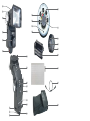
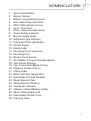
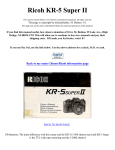
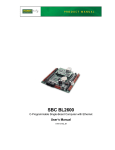
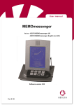
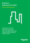
™
KF36 Manual Adjustable Flash
Harvest One Limited
1101 David House, 8-20 Nanking Street
Kowloon, Hong Kong
www.cactus-image.com
Printed in Hong Kong © 2009 Harvest One Limited
Instruction Manual
6
22
5
21
4
20
19
23
18
3
24
2
25
26
1
27
7
8
28
9
29
10
11
12
13
17
16
14
15
30
NOMENCLATURE
1.
2.
3.
4.
5.
6.
7.
8.
9.
10
11.
12.
13.
14.
15.
16.
17.
18.
19.
20.
21.
22.
23.
24.
25.
26.
27.
28.
29.
30.
Open Flash Button
Sensor Socket
Battery Compartment Cover
Illuminated Calculator Dial
ASA / DIN Indicator Arrow
Lens / Filter Slot
Zoom / Bounce Flash Head
Zoom Setting Indicator
Bounce Angle Scale
Sufficient Light Indicator
Calculator Dial Light Button
On-Off Switch
Ready Light
Mounting Foot Lock Lever
Mounting Foot
Shutter Cord Socket
AC Adapter / Power Grip Receptacle
Vari-Power Settings
Vari- Power Dial (Black Arrow)
Distance Scales (ft & m)
f-Stop Scale
ASA / DIN Film Speed Dial
Auto Mode Colored Wedges
Mode Selector Dial
Mode Selector Window
Vari Sensor Module
Alkaline / NiCad Battery Holder
28mm Wide Angle Lens
Detachable Shutter Cord
Carrying Case
1
! IMPORTANT SAFEGUARDS
When using your photographic equipment, follow the following
basic safety precautions:
1. Read and understand all instructions before use.
2 Do not leave any equipment unattended while in use. Close
supervision is necessary when any equipment is used by or
near children.
3. Care must be taken as burns can occur from touching the hot
parts of the flash.
4. Do not operate equipment with a damaged cord or if the
equipment has been dropped or damaged. Return appliances
to the nearest authorized service facility for examination, repair
or electrical or mechanical adjustment.
5. Do not let cord hang over the edges of table or counter or
touch hot surfaces.
6. If an extension cord is necessary, a cord with a suitable current
rating should be used. Cords rated for less amperage than the
equipment may overheat. Care should be taken to arrange the
cord so that it will not be tripped over or pulled.
7. Always unplug the equipment from the electrical outlet when
that is not in use. Never yank the cord or pull the plug from the
outlet directly. Grasp the plug then pull to disconnect instead.
8. Let the equipment cool first before putting away. Loop the cord
loosely around equipment when storing.
9. To protect against electric shock hazards, do not immerse this
equipment in water or other liquids.
10. To avoid electric shock hazard, do not disassemble this
equipment. Incorrect reassembly can cause electric shock
hazard when the equipment is used subsequently. Return
appliances to the nearest authorized service facility for
examination, repair or electrical or mechanical adjustment.
2
TABLE OF CONTENTS
Power Source
4
Ready Light
4
Battery Saving Circuit
4
Battery Operation
Inserting Batteries
Forming the Capacitor
Thyristor Circuit
5
Zoom / Bounce Flash Head
Zoom Position
Bounce Angle
6
Output Control
Vari Sensor Module
Mode Selector Dial
6
Calculator Dial
8
Sufficient Light Indicator
9
Attaching the Flash to the Camera
10
Shooting Automatically
On-Camera Direct Flash
On-Camera Bounce Flash
Off-Camera Direct and Bounce Flash
10
Shooting Manually
Direct Flash
Zoom
Bounce Flash
Vari-Power
14
Fill-in Flash
16
Multiple Flash Lighting
17
Specifications
Power Specifications
General Specifications
18
Calculator Dial Illustrations
19
Manual Operation Guide Numbers
20
Automatic f-stop Settings and Corresponding Ranges
21
Warranty
22
3
The purpose of this Instruction Manual is to familiarize you with your flash and
give you the basics for flash photography. Once you’ve used your flash for a
while, you may want more in-depth information on flash lighting techniques.
There is a wealth of information available on the internet. Books on this topic
are available in bookstore, library and local photo dealer. You may find it
helpful to visit Cactus’s website at www.cactus-image.com as well.
Power Source
Your flash operates on four 1.5 volts size AA batteries as a standard power
source. Alkaline batteries are recommended.
Ready Light
The flash is equipped with a Ready Light (13) with a 3-stage operation: It
glows red when the flash is at 1/2 power; glows green when the flash is at 3/4
power; and blinks red and green alternatively when the Battery Saving Circuit
is in operation and the unit is at full power.
The new Cactus KF-36 has a modified triggering circuit which allows you to
fire the flash before the Ready Light goes on. But be aware that
underexposures may result when the unit is fired before the Ready Light is on.
Battery Saving Circuit
Your flash unit has a built-in battery-saving circuit that acts to significantly
prolong battery life. When this circuit is in operation, the Ready Light will blink
red and green alternatively.
4
Battery Operation
Inserting Batteries
1.
Set the Flash Head to the straight-ahead 0゚position. Pushing with your
thumb from the front of the unit, slide and open the Battery Compartment
Cover (3) and take out the Battery Holder (27). NOTE: There is a stop
built into the cover to prevent it from coming all the way off the back. DO
NOT FORCE THE COVER.
2.
Insert four fresh 1.5 volt size AA alkaline batteries or NiCads, following
the battery positioning marked on the Holder.
3.
Insert the Holder into the battery compartment (align the square corner)
and slide the Battery Compartment Cover closed.
There are some simple procedures for getting the most out of your flash and
batteries. Always turn your unit off right after you’ve finished using it to prolong
battery life. Also, when storing your flash for a period of time, remove the
batteries to prevent possible damage from battery corrosion.
Replace the batteries if the red Ready Light fails to glow within 30 seconds.
Forming the Capacitor
When your flash is new or when it has not been used for a certain period of
time, the capacitor may lose its ability to store electricity. When this occurs,
you can “form” the capacitor as follows:
1.
Set the Mode Selector Dial (24) to the manual “M” position.
2.
With batteries in the flash, slide the On-Off Switch (12) to the RED “ON”
position.
3.
When the green Ready Light glows, fire the flash using the Open Flash
Button (1), allowing the Ready Light to glow 15 to 20 seconds first. After a
sequence of 5 flashes, your capacitor will then be formed and you are
ready to begin shooting.
Thyristor Circuit
Your flash has a unique power conservation system called “thyristor circuit”. In
any of the four auto modes, this circuit saves the excess energy not needed
for a proper exposure, thereby providing very fast recycling time and a greater
number of flashes per battery charge. The recycle time and the number of
flashes per charge both vary depending on the flash-to-subject distance and
the auto mode used. As you move the flash closer to the subject, the flash
recycles faster and is capable of providing more flashes per set of batteries.
5
Zoom / Bounce Flash Head
Zoom Position
The Zoom / Bounce Flash Head (7) allows you to coordinate the field coverage
of your flash with the field covered by your camera lens. Positions are marked
on the Zoom Setting Indicator (8) for wide, normal and tele – equivalent to
camera focal lengths of 35mm, 50/55 mm and 105mm. Extend or retract the
Zoom / Bounce Flash Head to the position which is closest to the focal length
of the camera lens you are using.
In addition, a 28 mm Wide Angle Flash Lens (28) is included in the package of
Cactus KF-36 Flash. Insert the flash lens into the Lens / Filter Slot (6), with the
tab on the lens at the bottom. The 28mm Flash Lens is designed to be used
with the Zoom / Bounce Flash Head in the wide position.
Bounce Angle
Cactus KF-36 will tilt to any of the five click positions (9) ( 0゚, 45゚, 60゚, 75゚, 90
゚), depending on the lighting you want to create. When the flash is set at 45゚,
60゚, 75゚or 90゚ position, you can bounce light off a reflective surface to create
softer lighting.
Output Control
Vari Sensor Module
Cactus KF-36 Electronic Flash is equipped with a removable Vari Sensor
Module (26) that measures the light reflected from the subject and other
reflective surfaces near the subject. This information is interpreted by a solid
state computer in the sensor which programs the flash to automatically provide
just the right amount of light required for a correct exposure. The practical
advantage is that you don’t have to change the f-stop on your camera lens
when you move closer to a subject or farther away. As long as your subject is
within the automatic operating range of the flash for that f-stop, the computer
automatically makes the adjustment for you.
In order to remove the Vari Sensor Module from the flash, pull it straight out
from the body of the flash. To mount the Module back on the flash, align the
black ridge at the back of the Module with the groove in the Sensor Socket (2)
and push the Module firmly into the flash.
6
Mode Selector Dial
The Mode Selector Dial (24) on the Vari Sensor Module allows you to set
Cactus KF-36 for manual operation or automatic operation with four different
f-stops on your camera lens. This provides you with a means for controlling the
depth of field in your photographs. Because the four f-stops vary with the
speed of the film you are using, each automatic mode is assigned a color.
The Mode Selector Dial may be set to any one of the following four auto
positions:
YELLOW: Utilizes the widest lens opening for relatively shallow depth of field
and provides greatest automatic operating range. Automatic
operating range with Zoom / Bounce Head in NORM position is
6-60 feet (1.8 – 18.3 meters).
RED:
Utilizes a medium lens opening for somewhat more depth of field.
The automatic operating range is shortened accordingly.
Automatic operating range with Head in NORM position: 5-30 feet
(1.5 – 9.1 meters).
BLUE:
Utilizes a smaller lens opening for greater depth of field. Automatic
operating range with Head in NORM position: 2-15 feet (0.7 – 4.4
meters).
PURPLE: Utilizes the smallest lens opening for maximum depth of field.
Automatic operating range with Head in NORM position: 2-11 feet
(0.7 – 3.3 meters).
For operating details, see section “Shooting Automatically” (page 10) and the
chart of Automatic f-stops and Corresponding Ranges (page 21).
In addition to the four auto positions, the Mode Selector Dial has a manual
position “M”. When set in this position, your flash unit will provide maximum
light output regardless of the flash-to-subject distance. Operating details are
given in the “Shooting Manually” section of these instructions (page 14).
To handle special situation, such as fill-in flash, multiple flash set-ups or for
freezing high-speed action, the Cactus KF-36 features a variable power
system. With this system, you can reduce the light output from full power to
1/2, 1/4 or 1/16 power by setting the Mode Selector Dial in the corresponding
marked position. For operating details, refer to the “Vari-Power” portion of the
“Shooting Manually” section (page 15).
7
Calculator Dial
The Calculator Dial (4) is a convenient built-in guide for determining flash
exposures. It is not electronically connected to the flash. After familiarizing
yourself with the meanings of the numbers and colors, you will find the dial a
very versatile tool. Under dim lighting conditions, press the Calculating Dial
Light Button (11) and the dial is illuminated.
Operation:
1.
Set the Zoom / Bounce Flash Head to the NORM position.
2.
Set the black arrow (19) of the Vari-Power Dial (inner ring of Calculator
Dial) to the FULL position (see photo A in Calculator Dial Illustrations,
page 19).
3.
Set the ASA / DIN film speed.
To set the Calculator Dial for the ASA (ISO) or DIN number of the film you are
using, turn the outer edge of the dial until the appropriate number on the ASA or
DIN scale is opposite to the white Film Speed Indicator Arrow (5). If the ASA or
DIN number of your film is not on the Calculator Dial, use the film speed chart
shown below to find the film speed location and align that speed with the white
arrow.
FILM SPEED SCALE
DIN
21
20
19
18
17
16
15
ASA 400 320 250 200 160 125 100
80
64
50
40
32
25
/
64
/
/
/
25
Dial
4.
27
400
26
/
25
/
24
23
/ 160
22
/ 100
Select auto operating mode.
There are four colored wedges (23) with trailing range lines on the
Calculator Dial. Each color represents an automatic operating mode
which corresponds to an automatic f-stop. Each mode takes into account
a combination of two things – the auto range and depth of field (greatest
sharpness in front and back of subject). Which colored mode you select
will depend on the combination you want.
Select the auto mode you want. The Calculator Dial will give you the
minimum and maximum auto range and correct f-stop setting for the auto
mode you’ve selected. To determine operating ranges of the selected
mode, look on the dial and find the colored wedge of the mode and the
range line that trails off from it. The number at the end of the line is the
8
closest distance from your subject that the flash can be properly used.
The number in the center of the wedge is the longest distance. The
number above the colored wedge is the f-stop number to set your camera
lens to.
If the colored wedges fall between two different f-stops, refer to the
Automatic f-stop Settings and Corresponding Ranges (page 21) to
determine the best f-stop to use.
Example: You’re using ASA / ISO 100 (DIN 21) film with the Flash Zoom
Head in the NORM position. You select the RED mode. Your flash range
would be 5 to 30 feet (1.5 to 9.1 meters) and the f-stop setting would be
f4.0 (see photo A).
5.
Select desired zoom position.
After setting up the Calculator Dial with the Zoom / Bounce Head in the
NORM position, you may wish to operate the flash unit with the Zoom /
Bounce Head in the WIDE and TELE position. When the Zoom / Bounce
Head is extended or retracted from the NORM position, the distance
scale on the Calculator Dial will change position automatically.
Example: With setting of ISO /ASA 100 (DIN 21), when the Zoom /
Bounce Head is set in the NORM position, the operating distance in the
Red mode is 5-30 feet (1.5-9.1 m). When the head is extended to TELE,
the operating range for the Red mode becomes 6-35 feet (1.8-10.6 m).
See photos A and B for comparison.
Sufficient Light Indicator
The Sufficient Light Indicator (10) on your flash lets you know whether the light
output is sufficient for a proper exposure before you take a picture. It may be
used when shooting in any of the four automatic modes, and is especially
helpful in bounce light situations that normally require complex exposure
calculations. To test an exposure using the Sufficient Light Indicator:
1.
Position your camera, flash, and subject just as you wish for the final
picture.
2.
Set the Mode Selector Dial on the Flash Sensor to the automatic mode
color which matches the mode wedge color already selected on the
Calculator Dial.
9
3.
Set your camera lens to the f-stop indicated above that colored wedge on
the Calculator Dial.
4.
Switch on the flash unit. After the green Ready Light glows, fire the flash
by pushing the Open Flash Button (1). If the flash exposure is adequate,
the green Sufficient Light Indicator (10) will glow for about 2 seconds
immediately after firing the flash. If it doesn’t light up, do one of the
followings: set your flash and camera to an automatic mode that uses a
wider f-stop opening; or, decrease the flash-to-subject distance.
Note: The Sufficient Light Indicator is for use in any of the four
Automatic Modes and will not light if the Mode Selector Dial on the
Sensor is set on manual “M” or if the Sensor is not connected to the
flash.
The Sufficient Light Indicator will, however, also light up when the Mode
Selector is set to one of the fractional Vari-Power positions. This is of NO
SIGNIFICANCE and should be disregarded.
Attaching the Flash to the Camera
Move the Mounting Foot Lock Lever (14) all the way to the left (unlock
position). Insert the Mounting Foot (15) into the accessory shoe of your
camera. Move the lever to the right until it clicks into the “LOCK” position.
Your flash has a built-in hot shoe contact. If your camera does not have a hot
shoe, connect the Shutter Cord (29) to the flash Shutter Cord Socket (16) and
to your camera’s “X” sync terminal. (Refer to your camera instructions for
specific information regarding your camera’s flash synchronization.)
Shooting Automatically
As you select a wider lens opening (a smaller f/number), you increase the
amount of light entering the lens, thereby increases the flash range and the
number of flashes per battery set. You’ll also benefit from faster recycling time.
Therefore, always try to select the auto mode that provides the greatest flash
range. If your subject distance is well within the flash range selected, all is
better. For example: your subject distance is 10 feet, your lens is a 50mm f2.0
or faster, and you are using ASA / ISO 100. The flash unit Calculator Dial
10
indicates a 10 foot maximum range in the Purple Mode, which corresponds to
f11. You decide to use this mode. While this selection will give you proper
exposure with significant depth of field, it will use most of the energy in the
flash capacitor. As a result, the batteries must work harder and longer to
re-energize, which causes longer recycling time between flashes and fewer
flashes per set of batteries.
The best auto mode for fastest recycling time and most flashes (but limited
depth of field) is the yellow mode. (The next best is RED, then BLUE, etc.) It
provides an enormous auto exposure range to 60 feet (up to 70 feet with the
Flash Head in the TELE position). And because you must use a wider lens
opening, it takes less light for exposure. The auto sensor shuts the light off
sooner, so a limited amount of energy from the capacitor is used and the
thyristor circuit holds the excess energy inside it. The batteries aren’t depleted
as quickly, so you get faster recycling time and more flashes.
Please note that while the f/number changes with the speed of the film / ISO,
the auto range remains constant.
On-Camera Direct Flash
This method of operation with your Cactus KF-36 allows you to photograph
subjects at maximum distances from the flash while still maintaining automatic
flash exposure control.
1.
Set your camera to the correct shutter speed for electronic flash. (Refer to
your camera instructions.)
2.
If you have not already done so, set the Zoom / Bounce Head to the
NORM position, and set the ISO you are using on the Calculator Dial
(page 8). The four colored wedges on the Calculator Dial now line up
below the four automatic f-stops you are using.
3.
Select any one of the four automatic mode color wedges and
corresponding f-stops on the Calculator Dial that provides the automatic
operating range or depth of field you desire. Generally speaking, the
yellow mode will provide the fastest recycling time and the most number
of flashes. If your lens doesn’t have an f-stop that corresponds to the
yellow mode, use the red mode instead.
4.
Turn the Mode Selector Dial on the Vari Sensor Module until the color
that corresponds to the f-stop you selected in step 3 above appears in the
Mode Selector Window (25) on the side of the Module.
5.
Set your camera lens to the auto f-stop you selected in step 3.
6.
Set the Flash Head to the 0゚ tilt (straight ahead) position.
11
Example: You wish to photograph a subject 10 feet away and desire
moderately great depth of field. Using ASA film / ISO 100 and the Zoom /
Bounce Head in the NORM position, set the Mode Selector Dial to the
Blue position and set your camera lens to f8. Your automatic operating
range is from 2 to 15 feet (0.6-4.5 m) (photo A).
7.
Slide the On-Off Switch to the RED “ON” position. Focus the camera. If
desired, test the exposure using the Sufficient Light Indicator (page 13).
Take the picture when the green Ready Light glows. Your flash unit will
automatically determine correct exposures without further adjustments as
long as you remain within the automatic range you have selected.
Zoom settings – If you wish to extend or retract the Zoom / Bounce Head to
the TELE or WIDE settings, this will not affect the operation of the automatic
sensing system of the flash. It will, however, alter your operating range and
flash light coverage (see Automatic f-stop Settings and Corresponding Ranges
in page 21).
Example: Using ISO 100 and the Zoom / Bounce Head in the TELE position,
set the Mode Selector Dial to the Blue position and your camera lens to f8.
Your automatic operating range is now from 2 to 18 feet, instead of 2 to 15 feet
as in the NORM position of step 6 above (see photo A and B for comparison).
On-Camera Bounce Flash
When the flash is set at 45゚, 60゚, 75゚ and 90゚, the light can be bounced off
the ceiling or other reflective surfaces to create a softer lighting. As a general
rule, set the tilt angle of the head so that the light is directed at the midpoint on
the ceiling between the flash and the subject.
1.
Set your camera to the correct shutter speed for electronic flash. (Refer to
your camera instructions.)
2.
If you have not already done so, set the Zoom / Bounce Head to the
NORM position and set the ISO or DIN film speed on the Calculator Dial.
3.
After positioning your subject, tilt the Flash Head to the desired bounce
angle.
4.
Select any one of the four automatic f-stops on the Calculator Dial that
provides the automatic operating range or depth of field you desire.
Turn the Mode Selector Dial on the Vari Sensor Module until the color
that corresponds to the f-stop you selected above appears in the window
on the side of the Vari Sensor Module.
12
Remember that the automatic operating range must be sufficient to
include the entire flash-to-bounce surface-to-subject distance.
5.
Set your camera lens to the auto f-stop you selected in step 4.
Example: Using ISO 100, bouncing the light off an 8 foot high ceiling onto
a subject at a total flash-to-reflector-to-subject distance of 20 feet (6.1 m)
from the flash, and desiring relatively shallow depth of field:
a)
Set the Flash Head tilt to the appropriate angle;
b)
Set the Flash Head to the NORM zoom position;
c)
Set your camera lens to f4.0;
d)
Set the Mode Selector Dial to RED.
Note: Bouncing off surfaces such as curtains or acoustical tile
ceilings will add to the effective distance between flash, bounce
surface and subject because they absorb light. Make sure the auto
mode operating distance covers this effective distance.
Your flash unit will automatically determine correct exposures without
further adjustments as long as you remain within the automatic range you
have selected.
6.
Slide the On-Off Switch to the RED “ON” position. Focus the camera. If
desired, test the exposure using the Sufficient Light Indicator (page 9).
Take the picture when the green Ready Light glows.
Off-Camera Direct and Bounce Flash
Cactus KF36 can be operated wirelessly with Cactus Wireless Flash Trigger.
Off camera flash provides better lighting control of your subject by placing
KF36 at various angles and distances without being hindered by wire. The
flash can then be aimed either directly at the subject or at many different types
of reflective surfaces such as ceilings, walls or photo umbrellas and still
maintain fully automatic exposure control and manual control.
13
Shooting Manually
Direct Flash
If you wish to use your flash in Manual Mode (for taking pictures beyond the automatic
flash range or when using multiple flash lighting), proceed as follows:
Set the Mode Selector Dial (24) to the manual “M” position.
Estimate the distance from the flash to the subject. The easiest way to do
this is to focus your camera and refer to the distance indicated on the
camera lens barrel after focusing.
Find the flash-to-subject distance on the Calculator Dial Distance Scale
and set your lens to the f-stop indicated above that distance. (Disregard
the colored wedges on the Dial when shooting in the manual mode.)
Example: If you are 40 feet from your subject and are using the NORM
flash head position and ISO 100, set your lens f-stop to f2.8. (photo A.)
Slide the On – Off Switch to the RED “ON” position. Check camera focus.
Take the picture when the green Ready Light glows.
Caution: For rapid sequence flash pictures in the manual mode, you may
fire your Cactus KF-36 as soon as the green Ready Light glows.
However, to prevent possible damage, avoid a continuous series of more
than 25 flashes and allow the unit to “rest” for 4 minutes between series.
Zoom
If you want to extend or retract your Zoom / Bounce Head to the TELE or
WIDE setting, it will affect your f-stop and / or operating range, and you should
recheck your Calculator Dial for new information.
Note: If you wish to mathematically calculate your f-stops, divide Guide
Number by flash-to-subject distance. Remember that Guide Number will
change with extension or retraction of the Zoom / Bounce Head. See
Manual Operation Guide Numbers (page 20) for a complete listing of
Guide Numbers for various films speeds (ASA /ISO and DIN) for each of
the three zoom head positions and Super Wide Angle Flash Lens.
14
Bounce Flash
Your flash can be used in the manual “M” mode for bounce flash at distances
beyond the maximum automatic operating range.
First, set Mode Selector Dial to manual “M”. To determine the proper exposure
when using bounce flash in manual mode, use any ONE of the following
methods:
1.
In rooms of average size and color, a good general rule is to open your
lens TWO f-stops wider than if you were shooting direct;
OR...
2.
After setting the proper ISO / DIN number on the Calculator Dial, find the
total flash-to-reflector-to-subject distance on Calculator Dial and note the
f-stop indicated above that distance. Open your lens ONE f-stop wider
than indicated on the dial;
Example: Photographing at a flash-reflector-subject distance of 20 feet
with ISO 100, flash f-stop is f5.6, but you must set your camera lens to
f4.0.
OR…
3.
If the total bounce distance exceeds the maximums appearing on
Calculator Dial, measure the distance from the flash to the reflecting
surface to the subject. Divide that total distance into the flash Guide
Number for the film speed / ISO you are using and the Zoom / bounce
Head position. Note the resulting number (round off the nearest f-stop),
and open your lens ONE f-stop wider.
Note: When figuring flash to subject distance using manual bounce
flash, be sure to consider the light absorption of the reflective surface.
Bouncing off surfaces such as curtains, for example, will add to the
effective distance between the flash, the reflector and the subject. To
ensure proper exposed pictures when bouncing off curtains or
acoustical tile ceilings, open your lens ONE additional f-stop over the
setting determined by any of the above methods.
Vari-Power
There are cases where you may wish to go beyond the basic “normal” manual
operation as explained above, such as flash fill-in outdoors, multiple flash light
ratio control, need for faster recycling time, faster action freezing or when you
want to use a specific f-stop not available in auto mode for depth of field
control.
15
To handle these needs, you can reduce the light output levels from full power
to 1/2, 1/4 or 1/16 power using your flash’s variable power system with
Vari-Power.
To operate the Vari-Power system:
1.
Set the black arrow of Vari-Power Dial (inner ring of the
1/2
1/4
1/16
Calculator Dial) to:
2.
Set Mode Selector Dial to:
3.
Increase (open) camera aperture by:
1/2
1/4
1/16
1 f-stop
2 f-stop
4 f-stop
As you turn the inner ring, Calculator Dial will automatically indicate the new
f-stop above the flash-to-subject distance.
Fill-in Flash
Your flash can be used outdoors in daytimes, either for better lighting on
overcast days or to reduce shadows on bright days.
1.
Set your camera to the correct shutter speed for synchronization with
electronic flash. (Refer to your camera instructions for the correct speed)
2.
Using your built-in or hand-held meter, determine the f-stop required for a
daylight exposure at the flash sync speed.
3.
Align Vari-Power Dial (19) to the camera-to-subject distance with the
f-stop indicated by the meter.
Example: Zoom / Bounce Head in NORM position, ISO 100 (DIN 21),
synchronized at 1/60, meter reading f16, camera-to-subject distance 5 ft. You
want strong fill-in flash. Rotate Vari-Power Dial (inner ring of Calculator Dial)
until f16 aligns with 5 feet, and your resulting Vari-Power reading is 1/2 (see
photo C). Recheck the film speed /ISO setting to make sure it hasn’t been
inadvertently moved.) You then change your Mode Selector Dial to read 1/2.
For normal rather than strong fill, change Vari-Power settings to 1/4.
Note: By zooming the Head from NORM to WIDE, you can change
exposure by 1/2 f-stop.
16
Multiple Flash Lighting
The Vari-Sensor Module on your flash makes multiple flash lighting easier,
because when you use your flash as a fill-in lighting with main flash, you can
“dial in” the lighting ratios.
1.
Set up your main flash and determine the f-stop you’re going to use.
2.
Set up your secondary flash unit at a distance equal to the main
flash-to-subject distance.
Example: The main flash unit must be in manual mode and have the
same power as your fill-flash unit. Set the Vari Sensor Dial on the fill-flash
unit to FULL position that gives you a main-flash / fill-flash ratio of 1:1. Set
the dial on the fill unit at 1/2 that gives you a main/fill ratio of 3:1 because
the main flash unit is putting out twice as much light as the fill flash, i.e.
the main flash gives out two units of light and the fill flash gives out one
unit of light, thus giving out a total of 3 units of light and creating an
overlap of one unit of light from each. A setting of 1/4 gives you a ratio of
5:1 and 1/16 gives you 17:1.
With this flexibility and accuracy, a multiple flash lighting set-up can be
tuned to achieve delicate nuances of creative effects.
3.
Another use of Vari-Power capability is in its “action-freezing” potential.
As the power output is reduced, the flash duration is shortened, thus
resulting in greater action-stopping ability.
17
Specifications
Power Specifications
BCPS (Beam Candle Power Seconds): 2500 (Manual)
Power Source: Four (4) AA batteries
Battery life: 100 flashes in manual full-power mode
Recycle Time: 10.4 seconds
All specifications are with Cactus KF-36 set in manual mode. In most cases,
recycle time and number of flashes will improve in the automatic mode if the
subject is at less than the maximum auto distance.
All specifications are approximate and number of flashes and recycling time
vary according to battery condition, temperature and other variables.
General Specifications
Flash Duration (approx.): Auto – 1/1,000 to 1/30,000 second
Manual – 1/1,000 second
Angles of Illumination:
Zoom Setting
Horizontal
Vertical
70 ゚
53 ゚
WIDE (35mm)
60 ゚
45 ゚
NORMAL (50mm)
46 ゚
34 ゚
TELE (105mm)
27 ゚
20 ゚
Super WIDE (28mm) w/Wide
Angle Flash Lens inserted
Color Temperature: 6,000゚K
Camera / Flash Synchronization Connections: Hot Shoe, Shutter Cord
Weight (without batteries): 14.9 oz. (423 g)
Dimensions (Head in 0゚position): 4” W x 5.2” H x 4.2” D
(100 mm W x 130 mm H x 105 mm D)
Accessories Included: 28 mm Wide Angle Flash Lens, PC-1 Shutter Cord,
Carrying Case
Specifications subject to change without notice
18
Calculator Dial Illustrations
Photo A
ISO: DIN21/ASA100
Flash Head: NORM
Power: Full
Photo B
ISO: DIN21/ASA100
Flash Head: TELE
Power: Full
Photo C
ISO: DIN21/ASA100
Flash Head: NORM
Focal length: 5 ft
Aperture: F16
19
20
64
56
80
96
112
35
50
60
70
Super Wide (28mm)
Wide (35mm)
Normal (50mm)
Tele (105mm)
19
17
24
29
34
11
15
18
21
Super Wide (28mm)
Wide (35mm)
Normal (50mm)
Tele (105mm)
DIN Film Speed:
15
(DIN-Meters):
ASA Film Speed:
25
(ASA-Feet):
38
33
27
19
20
125
107
90
62
80
Manual Operation Guide Numbers
43
37
31
21
21
140
120
100
70
100
100 140
126 140 200
90
48
41
34
24
22
54
46
38
27
23
61
52
43
31
24
85
73
61
43
27
156 177 200 280
134 152 170 240
112
80
135
115
100
65
31
460
400
325
230
125 160 200 400 1000
21
Mode f-stop
PURPLE
Mode f-stop
BLUE
Mode f-stop
RED
Mode f-stop
YELLOW
Zoom Flash Head Position
Mode f-stop
PURPLE
Mode f-stop
BLUE
Mode f-stop
RED
2-9 ft.
(0.7 - 2.6 m)
2 - 6 ft.
2 - 12 ft.
(0.7 - 3.7 m)
2 - 9 ft.
(0.7 - 2.6 m)
(0.7 - 1.8 m)
5 - 25 ft.
(1.5 - 7.5 m)
3 - 18 ft.
(1.0 - 5.5 m)
5 - 50 ft.
(1.5 - 15.1 m)
4 - 35 ft.
(1.2 – 10.6m)
Wide
11.0
8.0
35 mm
11.0
8.0
4.0
2.0
21
100
28 mm
8.0
5.6
4.0
2.0
20
80
Super Wide
5.6
4.0
2.8
1.4
1.0
YELLOW
2.0
19
15
DIN Film Speed
Mode f-stop
64
25
ASA Film Speed
50 mm
Normal
16.0
11.0
5.6
2.8
23
160
(0.7 – 3.3 m)
2 - 11 ft.
(0.7 – 4.4 m)
2 - 15 ft.
(1.5 - 9.1 m)
5 - 30 ft.
(1.8 – 18.3 m)
6 - 60 ft.
11.0
8.0
4.0
2.0
22
125
Automatic f-stop Settings and Corresponding Ranges
Tele
22.0
16.0
8.0
4.0
27
400
(0.7 – 3.7 m)
2 - 12 ft.
(0.7 – 5.5 m)
2 - 18 ft.
(1.8 – 10.6 m)
6 - 35 ft.
(2.1 – 21.3 m)
7 - 70 ft.
105 mm
16.0
11.0
5.6
2.8
24
200
Warranty
The limited warranty set forth below is given by Harvest One Limited in the
world with respect to the Cactus brand Flash KF36 purchased with this limited
warranty.
Your Cactus Flash KF36 or other contents, when delivered to you in new
condition in its original container, is warranted against defects in materials or
workmanship as follows: for a period of one (1) year from the date of original
purchase, defective parts or a defective Cactus Flash KF36 returned to our
authorized dealers, as applicable, and proven to be defective upon inspection,
will be repaired with new or comparable rebuilt parts or exchanged for a new
Flash KF36 as determined by Harvest One Limited or the authorized dealers.
This limited warranty shall only apply if the flash is used in conjunction with
compatible camera and flash equipment, as to which items, Harvest One
Limited, shall have no responsibility.
This limited warranty covers all defects encountered in normal use of Cactus
Flash KF36 and does not apply in any of the following cases:
(a) Loss of or damage to the Flash due to abuse, mishandling, improper
packaging by you, alteration, accident, electrical current fluctuations.
(b) Failure to follow operating, maintenance or environmental instructions
prescribed in Cactus user's manual.
(c)
Receive services performed by someone other than Harvest One Limited
or authorized dealers.
(d) Without limiting the foregoing, water damage, sand/corrosion damage,
battery leakage, dropping the flash, scratches, abrasions or damage to
the body, or damage to the hot shoe or PC cables, will be presumed to
have resulted from misuse, abuse or failure to operate the flash as set
forth in the operating instructions.
NO IMPLIED WARRANTY, INCLUDING ANY IMPLIED WARRANTY OF
MERCHANTABILITY OR FITNESS FOR A PARTICULAR PURPOSE,
APPLIES TO THE FLASH AFTER THE APPLICABLE PERIOD OF THE
EXPRESS LIMITED WARRANTY STATED ABOVE, AND NO OTHER
EXPRESS WARRANTY OR GUARANTY, EXCEPT AS MENTIONED ABOVE,
GIVEN BY ANY PERSON OR ENTITY WITH RESPECT TO THE FLASH
SHALL BIND HARVEST ONE LIMITED. HARVEST ONE LIMITED SHALL NOT
BE LIABLE FOR LOSS OF REVENUES OR PROFITS, INCONVENIENCE,
EXPENSE FOR SUBSTITUTE EQUIPMENT OR SERVICE, STORAGE CHARGES,
LOSS OR CORRUPTION OF DATA, OR ANY OTHER SPECIAL, INCIDENTAL
OR CONSEQUENTIAL DAMAGES CAUSED BY THE USE OR MISUSE OF,
22
OR INABILITY TO USE, THE FLASH, REGARDLESS OF THE LEGAL
THEORY ON WHICH THE CLAIM IS BASED, AND EVEN IF HARVEST ONE
LIMITED HAS BEEN ADVISED OF THE POSSIBILITY OF SUCH DAMAGES.
IN NO EVENT SHALL RECOVERY OF ANY KIND AGAINST HARVEST ONE
LIMITED GREATER IN AMOUNT THAN THE PURCHASE PRICE OF THE
CACTUS FLASH KF36 SOLD BY HARVEST ONE LIMITED OR ITS
AUTHORIZED DEALERS AND CAUSING THE ALLEGED DAMAGE.
WITHOUT LIMITING THE FOREGOING, YOU ASSUME ALL RISK AND
LIABILITY FOR LOSS, DAMAGE OR INJURY TO YOU AND YOUR
PROPERTY AND TO OTHERS AND THEIR PROPERTY ARISING OUT OF
USE OR MISUSE OF, OR INABILITY TO USE, THE CACTUS FLASH KF36
NOT CAUSED DIRECTLY BY THE NEGLIGENCE OF HARVEST ONE
LIMITED. THIS LIMITED WARRANTY SHALL NOT EXTEND TO ANYONE
OTHER THAN THE ORIGINAL PURCHASER OF HARVEST ONE LIMITED,
OR THE PERSON FOR WHOM IT WAS PURCHASED AS A GIFT, AND
STATES YOUR EXCLUSIVE REMEDY.
23