1
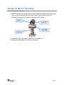
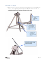
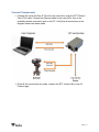
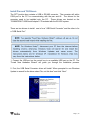
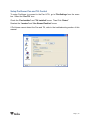
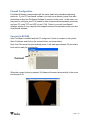
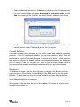
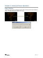
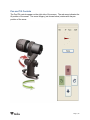
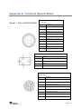
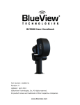
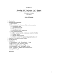
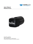
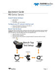
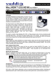
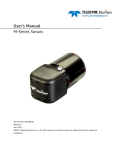
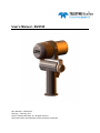
User’s Manual - BV4100
Part Number: 204344-01
Revision:-, February, 2013
©2013 Teledyne BlueView, Inc. All rights reserved
All product names are trademarks of their respective companies.
System Contents
The BV4100 system includes the following the following:
Sonar Head
Pan and Tilt Unit
Sonar Pan and Tilt Junction Box
Tripod with Case
Shipping Case
Hex Driver
Cable, Cat5, Ethernet
Cable, USB
Cable, Power
ProViewer CD
USB Driver CD
BV4100 User’s Handbook
BV4100 Quickstart Guide
P-Series Manual
Page | 2
Table of Contents
System Contents .......................................................................................................... 2
Chapter 1: Introduction ................................................................................................... 6
Chapter 2: Bench Top Setup ............................................................................................ 7
Connect Components .................................................................................................. 9
Install Pan and Tilt Drivers .......................................................................................... 10
Install Software ........................................................................................................ 12
Setup ProViewer Pan and Tilt Control ............................................................................. 13
Setup PC IP Address................................................................................................. 14
Firewall Configuration ................................................................................................ 15
Connect to BV4100 ................................................................................................... 15
Dual Frequency Sonar ............................................................................................... 16
Running ProViewer ................................................................................................... 17
Firewall Software ..................................................................................................... 18
Shutdown .............................................................................................................. 18
Chapter 3: Advanced Sonar Operation .............................................................................. 19
Image Calibration ..................................................................................................... 19
Pan and Tilt Controls ................................................................................................. 20
Chapter 4: Troubleshooting ............................................................................................ 21
Sonar/Pan and Tilt Connection Issues ............................................................................ 21
Pan and Tilt Connection Issues .................................................................................... 21
Change USB ports .................................................................................................... 21
Check Pan/Tilt Settings in ProViewer ............................................................................. 21
Verify USB Com Port ................................................................................................. 22
Reinstall Drivers....................................................................................................... 22
Verify Com Port Settings ............................................................................................ 22
Check Connectors .................................................................................................... 23
Check Power .......................................................................................................... 23
Sonar Head Connection Issues .................................................................................... 23
Rerun ProViewer Software .......................................................................................... 23
Reboot PC and Sonar................................................................................................ 23
Check Network Settings ............................................................................................. 24
Check Connectors .................................................................................................... 24
Check Power .......................................................................................................... 24
Page | 3
Still not working? ...................................................................................................... 24
Chapter 5: Maintenance ................................................................................................ 25
Before Use ............................................................................................................. 25
After Use ............................................................................................................... 25
Appendix A: Technical Specifications ................................................................................ 26
Sonar / Pan and Tilt Cable ...................................................................................... 26
Appendix B: Mechanical Drawings ................................................................................... 27
Page | 4
Teledyne BlueView, Inc. has made every effort to ensure the accuracy and
completeness of this document; however, because ongoing development efforts are made
to continually improve the capabilities of our products, we cannot guarantee the accuracy of
the contents of this document. We disclaim liability for errors, omissions, or future changes
herein.
©2013 Teledyne BlueView, Inc. All rights reserved. No part of this publication may be
copied, reproduced, or translated, without the prior written consent of Teledyne
BlueView, Inc. No part of this publication may be stored or transmitted in any electronic
form without the prior consent of Teledyne BlueView, Inc. Any unauthorized use is a
violation of copyright laws.
Warning! This device should not be used as a navigational aid to prevent collision,
grounding, boat damage, or personal injury.
Warning! This product contains lead, a chemical known to the state of California to
cause cancer, birth defects and other reproductive harm. Handling and/or opening this
unit may result in exposure to lead, in the form of solder.
Warning! Disassembly and repair of this electronic unit should only be performed by
authorized service personnel. Any modification of the serial number or attempt to repair
the original equipment or accessories by unauthorized individuals will void the warranty.
Warning! Changes or modifications to this unit not expressly approved by the party
responsible for compliance may void the user’s authority to operate this equipment.
Warning! This equipment contains High Voltage electronics. Tampering with or using
damaged equipment could lead to serious injury.
Warranty Information:
The sonar is backed by a standard 12-month parts and labor warranty policy. See
Appendix D for more information.
For more information on safety and/or maintenance issues please call Teledyne
BlueView, Inc. at 206.545.7260.
Page | 5
Chapter 1: Introduction
BlueView 2D imaging sonar provides streaming sonar imagery, making it easy to search
in low and zero visibility water. BlueView has coupled high-performance imaging
capability with a powerful software package creating one of the world’s most versatile
underwater imaging systems available today.
The BV4100 provides stationary positioning of BlueView 2D imaging sonar systems. A
digitally controlled pan and tilt unit provides control of the orientation of the sonar. This
manual covers setup, installation, operation, and technical specifications of the system.
Advanced sonar technology, rugged design, and powerful software are just a few
highlights of the sonar system. This manual explains imaging sonar interpretation and
provides instructions on the installation and operation of the sonar system. For detailed
information on using the sonar imaging software, please see the ProViewer Software
Handbook found both on the software CD as well as under the software’s help menu.
The BV4100 ships with any of the 2D imaging sonar systems offered by BlueView. For
specific details on individual sonar head specifications, see the P-Series manual.
Page | 6
Chapter 2: Bench Top Setup
Assemble the Hardware
Attach the sonar to the sonar clamp by loosening the four cap screws, sliding the
sonar in, and re-tightening the four cap screws. Use the stickers and side
indicators to determine the up/down orientation of the sonar.
Connect the Pan & Tilt cable to the Pan & Tilt connector.
Connect the Sonar cable to the Sonar connector.
Page | 7
Assemble the Tripod
Attach the sonar to the sonar clamp by loosening the four cap screws, sliding the
sonar in, and re-tightening the four cap screws. Use the stickers and side
indicators to determine the up/down orientation of the sonar.
Page | 8
Connect Components
Connect the sonar and Pan & Tilt unit to the control box using the SPT (Sonar /
Pan & Tilt) cable. Connect the Ethernet cable to the control box, then to an
available network connection port on the PC. Verify that all connections in the
diagram below have been made.
Once all the connections are made, connect the SPT Junction Box to an AC
Power supply
Page | 9
Install Pan and Tilt Drivers
The SPT junction box contains a USB to RS-485 converter. The converter will add a
COM port to the PC for communicating with the pan and tilt. The drivers for the
converter need to be installed onto the PC. These drivers are located on the
“COMMFRONT USB Serial Adapter” CD included with the BV4100 system.
There are two drivers to install: one is for a “USB Serial Converter” and the other is for
a “USB Serial Port.”
1. Connect the USB port on the control box to an available USB port on the PC. The
“Found New Hardware Wizard” will guide you through the installation process.
2. First, the USB Serial Converter driver will install. When prompted to use Windows
Update to search for the driver select “No, not this time” and click “Next.”
Page | 10
3. Select “Install from a list or specific location” to install the driver from CD and
click “Next.”
4. Select “Search for the best driver in these locations” and check the box of
“Search removable media (floppy, CD-ROM…)”. Then click on the “Next” button.
5. When the driver is successfully installed the following window will pop up. Click
“Finish” to complete the installation of the first driver.
Page | 11
6. The 2nd “Found New Hardware” window will pop up prompting the driver
installation for “USB Serial Port”. DO NOT CLOSE THIS WINDOW! When
prompted to use Windows Update to search for the driver select “No, not this
time” and click “Next.”
7. Repeat steps 3-5 from above.
8. To confirm the drivers are installed successfully, check the Windows Device
Manager (in Windows XP, go to the Control Panel
Performance and
System, click the Hardware tab, then the Device Manager
Maintenance
button). Take note of the COM port number assigned to the USB COM port.
To access the Windows Device Manager click “Start” then RIGHT CLICK on my
computer in the start menu and select “Manage”. Click on “Device Manager” in
the left panel. Expand “Ports (COM and LPT)” and “Universal serial bus
controllers”. A new “USB Serial Port” should appear in the “Ports” section and a
“USB Serial Converter” should appear in the “Universal serial bus controllers”
section.
Install Software
Note: Running other applications in conjunction with the ProViewer Software may affect
performance of one or both of the applications.
1) Place the ProViewer CD-ROM in the CD-ROM drive. Installation will start
automatically.
If the CD-ROM drive does not automatically run:
Select Run from the Start menu, and type x:\setup in the Open box (where x is
the drive letter for the CD-ROM drive), then click OK.
2) The Welcome window opens. Click Next.
3) Follow the instructions on the screen to complete the installation
Page | 12
Setup ProViewer Pan and Tilt Control
To setup ProViewer to connect to the Pan & Tilt, go to File>Settings from the menu
bar. Select the “Pan/Tilt” icon.
Check the “Pan Installed” and “Tilt Installed” boxes. Then Click “Detect.”
Deselect the “Inverted” and “Use Stowed Position” boxes.
If ProViewer cannot detect the Pan and Tilt, refer to the troubleshooting section of this
manual.
Page | 13
Setup PC IP Address
The IP address on the interface PC will need to be set to a static IP: 192.168.1.3.
Windows XP
Control Panel
Network
To access a PC’s IP address in Windows, click Start
Connections and double click on the computer’s Ethernet port (usually Local Area
Connection 1). Right click and select ‘Properties’ then double click on ‘Internet Protocol
(TCP/IP)’ in the list of components. Make sure the IP address is set as shown below:
Windows Vista/7
To access a PC’s IP address in Windows Vista, click Start>Control Panel>Network
and Internet>Network and Sharing Center>Manage network connections.
Right click the connection that should be changed, and click Properties. You may be
asked for an administrator password.
Click the Networking tab. Under This connection uses the following items, click
Internet Protocol Version 4 (TCP/IPv4), and then click Properties.
As described in the previous section, set the IP address to 192.168.1.3, and the subnet
mask to 255.255.255.0.
Page | 14
Firewall Configuration
ProViewer Software communicates with the sonar head using standard networking
protocols. If your PC has firewall software, you may see a warning ‘popup’ that asks
permission to allow the ProViewer Software to connect to the sonar. In that case, you
may need to configure your PC’s firewall to allow communications between your sonar
and your PC using TCP and UDP on port 1149. Refer to your anti-virus/firewall
software vendor or your computer tech support resources for assistance with your antivirus/firewall software.
Connect to BV4100
After ProViewer is installed and the PC configured, it’s time to connect to the system.
Open ProViewer and click on the connect button, as shown below.
Note: that if the sonar has just received power, it will take approximately 30 seconds to
boot and be ready for a connection.
Connect
When the connect button is pressed, ProViewer will connect automatically to the sonar
and the pan & tilt.
Page | 15
Dual Frequency Sonar
Some BlueView products operate at more than one center frequency. Those sonars are
called ‘multi-head’ sonars. When connecting to a multi-head sonar, the ‘Sonar Devices’
window will show you all the sonar heads available to connect to:
Simply double-click the head you want to use, or select the head and click the ‘connect’
button.
If the sonar is already connected to a sonar head, switch the head by pressing the
“Home” key.
Page | 16
Running ProViewer
Once your sonar system is connected and turned on, it's time to connect your PC to the
sonar.
1. The IP address on the user’s PC will need to be set either to “Obtain an IP
address automatically,” or to a static IP: 192.168.1.x where x is any number
besides 45 that doesn’t conflict with the user’s system:
2. Open the ProViewer Software on the User Computer and click on the connect
button.
3. The ProViewer software will display the available sonar heads to connect to.
Page | 17
4. Select the desired head and click Connect, or just double click the desired head.
5. If a sonar head still does not appear when used in stand-alone mode, click the
Add button and type 192.168.1.45, the default Sonar IP address for the Sonar.
6. For Troubleshooting issues, please visit Chapter 4 “Troubleshooting”. If you still
cannot connect, contact Teledyne BlueView, Inc. for support
Firewall Software
ProViewer Software communicates with the Sonar Head using standard networking
protocols. If your PC has firewall software, you may see a warning “popup” that asks
permission to allow the ProViewer Software to connect to the Sonar. In that case, you
may need to configure the firewall to allow communications between your Sonar and
your PC using TCP and UDP on port 1149. Refer to your anti-virus software vendor or
your computer tech support resources for assistance with your anti-virus software.
Shutdown
To shutdown the sonar, close the Sonar Window by clicking on the X icon in the top
right-hand corner of the window, or select Exit from the File menu to close the entire
program. To avoid data loss, be sure to close and save any sonar data files before
removing the sonar power. It is now safe to power down the sonar or disconnect the
sonar Ethernet cable from the computer.
When power cycling the sonar, be sure to allow at least 10 seconds of ‘off time’ before
turning the sonar back on.
Page | 18
Chapter 3: Advanced Sonar Operation
Image Calibration
If an image looks broken or misaligned, press CTRL-J to bring up the Image Calibration
dialog. The slider will align the center of the image.
Page | 19
Pan and Tilt Controls
The Pan/Tilt controls appear on the right side of the screen. The red arrow indicates the
tilt position of the sonar. The sonar imagery (not shown below) rotates with the pan
position of the sonar.
Page | 20
Chapter 4: Troubleshooting
This section is designed to help you quickly identify and solve issues dealing with the
inability to connect the BV4100 system from a PC. The following approach attempts to
test different potential causes in a way that optimizes the debugging process.
Sonar/Pan and Tilt Connection Issues
The Sonar Head and Mechanical Pan & Tilt components run on nearly independent but
parallel networks. Each component has its own connector and conductor sets for
communications all the way back to the computer. This can help isolate problems
quickly since the only items shared are the DC power supply, DC power lines, and SPT
Cable. Try running through the individual troubleshooting components described
further in this chapter.
Pan and Tilt Connection Issues
Change USB Ports
Verify Pan/Tilt Settings in ProViewer
Verify USB Com Port
Reinstall P&T Drivers
Check Connectors
Check Power
Change USB ports
Change the USB port used for this connection on the PC.
If you were not able to connect to the pan and tilt, go on to the next section “Verify
Pan/Tilt Settings in ProViewer”
Check Pan/Tilt Settings in ProViewer
Verify that the ProViewer “File>Settings>Pan/Tilt” dialog is set properly. This is outlined
earlier in this manual.
If you were not able to connect to the pan and tilt, go on to the next section “Verify USB
Com Port”
Page | 21
Verify USB Com Port
The pan and tilt connects to the PC through a USB-to-RS485 converter located in the
SPT box. When the USB connection is made, and all the drivers are installed properly,
this connection will show up in the “Device Manager/Ports (Com and LPT)” as a USB
Com Port. If you do not see the USB Com port listed in this list, then either the device
drivers are not installed properly or the USB-to-RS485 converter is not functioning
properly.
If you were not able to connect to the pan and tilt, go on to the next section “Reinstall
Drivers”
Reinstall Drivers
Try reinstalling the drivers. Refer to the “Installing the Pan and Tilt Drivers” section in
this manual.
If you were not able to connect to the pan and tilt, go on to the next section “Reinstall
Drivers.”
Verify Com Port Settings
Verify the Com Port Settings. They should be set as follows: 9600 baud, 8 data bit,
parity none, 1 stop bit, no flow control.
If you were not able to connect to the pan and tilt, go on to the next section “Check
Connectors.”
Page | 22
Check Connectors
It is not uncommon for topside connectors to get pulled out of their ports or subsea
connectors to get corroded. Power-down the system, and check the condition and
proper seating of all connectors in the system.
If you were not able to connect to the sonar, go on to the next section “Check Power”
Check Power
If the pan and tilt does not receive the correct DC voltage on the correct pins, it can not
operate properly. Faulty power supplies, tripped breakers, and damaged cables can all
be the source of this problem. The best way to verify proper voltage is by measuring
the voltage at the sonar connector using a multimeter. Refer to the hardware manual
using the detailed connector/pin information in Appendix A of the is manual
Sonar Head Connection Issues
Rerun ProViewer Software
Reboot PC and Sonar
Check Network Settings
Check Connectors
Check Power
Rerun ProViewer Software
If a sonar did not complete its boot process before ProViewer was opened, it may have
missed that sonar. Rerunning the software can fix this.
If you were not able to connect to the sonar, go on to the next section “Reboot PC and
Sonar”
Reboot PC and Sonar
Power down both the sonar and computer, wait 10 seconds, then power everything up.
This can solve network configuration problems that may have come about. The sonar
takes 35 seconds to boot up, so do not be surprised at sporadic network connectivity
during this boot up process. Once everything is back up and running, open the
ProViewer software and try to connect to the sonar.
If you were not able to connect to the sonar, go on to the next section “Check Network
Settings”
Page | 23
Check Network Settings
Refer to the “Setup PC IP Address” section of this manual. Also ensure that ProViewer
is an “allowed” program in your firewall settings.
If you were not able to connect to the sonar, go on to the next section “Check
Connectors”
Check Connectors
It is not uncommon for topside connectors to get pulled out of their ports or subsea
connectors to get corroded. Power-down the sonar, and check the condition and proper
seating of all connectors in the system. Once you have verified condition and proper
seating of all connectors, re-power the Sonar, wait 35 seconds, then try to reconnect to
the sonar from ProViewer software.
If you were not able to connect to the sonar, go on to the next section “Check Power”
Check Power
If the sonar does not receive the correct DC voltage on the correct pins, it can not
operate properly. Faulty power supplies, tripped breakers, and damaged cables can all
be the source of this problem. The best way to verify proper voltage is by measuring
the voltage at the sonar connector using a multimeter. Refer to the hardware manual
for your specific sonar for detailed connector/pin information
Still not working?
Please contact us:
Teledyne BlueView, Inc. Customer Support
www.blueview.com
206-545-7260
8am – 4pm PST Mon through Fri
Page | 24
Chapter 5: Maintenance
Before Use
1. Prior to assembly of components, ensure that all connector contacts are clean,
dry and free of dirt and/or corrosion.
2. Inspect sacrificial zinc anode on rear bulkhead of sonar head and replace if it
appears that more than half of the anode has been lost to corrosion.
3. Inspect all cables and connectors for abrasion, cuts or cracks. Repair or replace
as needed.
4. Inspect anodized sonar shell and front and rear bulkheads for excessive
corrosion. If there is any question as to usability with the extent of any corrosion,
contact Teledyne BlueView, Inc.
After Use
1. After use, rinse the sonar, rear connector on the sonar, and the sonar cable with
a solution of mild soap and fresh water. At this time, inspect all components for
corrosion, wear or damage. This includes the sonar, connectors, cables, and
anode. Replace any component showing corrosion or damage.
2. Clean the connectors on the sonar cable and the connector on the rear bulkhead
of the sonar unit with alcohol. (Note: the connector on the rear bulkhead of the
sonar unit is NOT a field replaceable item. If any damage is detected, please
contact Teledyne BlueView, Inc. for an RMA number to return the sonar to the
factory for replacement, repair, and re-test.)
3. Apply 3M silicon spray lube or equivalent to the external mating surface of the
sonar connector and the internal mating surface of the sonar cable connector. Do
not grease.
4. Check that the anode is in place and it has not deteriorated. Replace as
necessary. More than 50% should remain or the anode should be replaced.
When replacing the anode, make sure the surface under the anode is bare and
bright before the anode is installed to ensure good electrical contact. For
replacement anode, please contact Teledyne BlueView, Inc.
Page | 25
Appendix A: Technical Specifications
10 Pin Connector to Sonar (Impulse MKS310-CCP-RA)
Sonar / Pan and Tilt Cable
Pin
Function
1
Ethernet RX+ (to sonar)
2
Ethernet RX- (to sonar)
3
Ethernet TX+ (to sonar)
4
+24V DC
5
+24V DC
6
Ethernet TX- (to sonar)
7
Ground
8
Ground
9
N/C
10
N/C
4 Pin Connector to Pan & Tilt Unit (Impulse LPMIL-4-FS)
Pin
Function
1
DC Common
2
+24V DC
3
Data B
4
Data A
8 Pin Connector to Sonar and Pan & Tilt Unit (Souriau
UTG612-8PN)
Pin
Function
A
Ethernet RX+ (to sonar)
B
Ethernet RX- (to sonar)
C
Ethernet TX+ (to sonar)
D
+24V DC
E
24 DC Common
F
Ethernet TX- (to sonar)
G
Data A (to P&T)
H
Data B (to P&T)
Page | 26
Appendix B: Mechanical Drawings
All Dimensions shown in Inches
Page | 27