1
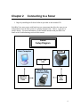
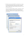
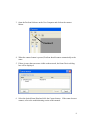
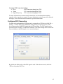
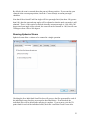
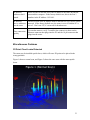
ProScan Software Handbook Part Number: 202667-01 Revised April 2012 ©BlueView Technologies, Inc. All rights reserved. All product names are trademarks of their respective companies. Table of Contents Chapter 1 Welcome ..................................................................... 3 Overview ......................................................................................................................... 3 System Recommendations .............................................................................................. 3 Installation....................................................................................................................... 3 Technical Support ........................................................................................................... 5 License Agreement ......................................................................................................... 5 Chapter 2 Chapter 3 Connecting to a Sonar ................................................. 6 Software Basics ........................................................... 9 Typical Screenshot .......................................................................................................... 9 Toolbar ............................................................................................................................ 9 Range Controls.............................................................................................................. 11 Playback Controls ...................................................................................................... 11 Chapter 4 Sonar Controls........................................................... 12 Sonar Control ................................................................................................................ 12 Image Calibration.......................................................................................................... 13 Chapter 5 Network Streaming ..................................................... 13 Configure Network ....................................................................................................... 14 Configure GPS Timecoding .......................................................................................... 15 Chapter 6 Saving and Reviewing Data ........................................ 16 Configure Recording ..................................................................................................... 16 Chapter 7 Pan & Tilt Configuration .............................................. 17 Configure Pan/Tilt ........................................................................................................ 17 Setup ............................................................................................................................. 17 Orientation .................................................................................................................... 18 Pan & Tilt Orientation ...................................................Error! Bookmark not defined. Beams Inverted ............................................................................................................. 18 Home Position............................................................................................................... 18 Calibration..................................................................................................................... 19 Chapter 8 Pan & Tilt Operation ..................................................... 20 Connecting to a Pan/Tilt ............................................................................................... 20 Pan/Tilt Controls ........................................................................................................... 20 Home Position............................................................................................................... 21 Chapter 9 Rotational Scanning ...................................................... 22 Running Single Scans ................................................................................................... 22 Running Spherical Scans .............................................................................................. 23 3D Point Cloud Files..................................................................................................... 24 Geo-referencing the 3D Point Clouds ........................................................................... 25 Playing back a Scan ...................................................................................................... 27 Appendix A Troubleshooting .................................................... 28 Connectivity Problems .................................................................................................. 28 Troubleshooting Table .................................................................................................. 32 1 Miscellaneous Problems ............................................................................................... 33 BlueView Customer Support ........................................................................................ 35 Appendix B Advanced Settings ................................................. 36 Sonar Gain and Time Variable Gain ..............................Error! Bookmark not defined. Detected Points ............................................................................................................. 36 Image Filters ................................................................................................................. 36 BlueView Technologies has made every effort to ensure the accuracy and completeness of this document; however, because ongoing development efforts are made to continually improve the capabilities of our products, we cannot guarantee the accuracy of the contents of this document. We disclaim liability for errors, omissions, or future changes herein. The accompanying Software and Documentation are proprietary products owned by BlueView Technologies, Inc., and protected under U.S. and international copyright law. Except as authorized under this License Agreement, the Software may be used only on computers owned, leased, or otherwise controlled by you. You may not reverse assemble, reverse compile, or otherwise translate ProViewer. Copyright © 2003-2009 BlueView Technologies Corp. All rights reserved. No part of this publication may be copied, reproduced, or translated, without the prior written consent of BlueView Technologies. No part of this publication may be stored or transmitted in any electronic form without the prior consent of BlueView Technologies. Any unauthorized use is a violation of copyright laws. ProScan® is a registered trademark of BlueView Technologies Corp. 2 Chapter 1 Welcome Overview This manual describes the features and operational instructions for BlueView Technologies’ ProScan software. ProScan provides an interface between BlueView’s line of MicroBathymetry (MB) products and third party bathymetry / line scanner software packages. ProScan also serves as a graphical user interface to the MB sonar, providing controls for collection, threshold processing, and data streaming. ProScan offers an interface for digital pan and tilt units that provide extra functionality, such as real-time angle adjustments and rotational scanning. ProScan can display, record, and stream live data from the MB sonar as well as open files for post processing or save data from rotational scans as 3D Point Cloud files. System Recommendations For best performance, ProScan requires a system that meets or exceeds the following requirements for optimum performance. Windows XP, Vista, or 7 operating system Dual-Core 1.8 GHz or faster processor 2GB or more of RAM 10GB or more of free disk space CD-ROM drive for installation 2 100Mbit or higher Ethernet interfaces 1 serial interface with a DB9 connection. 2 USB Ports Installation To install ProScan, just insert the ProScan CD into your computer’s CD-ROM drive. You may also launch the installation by double clicking on setup.exe in the CD’s root directory. Follow the instructions to complete the installation. NOTE: You must have administrator privileges to install ProScan. If you have a personal firewall enabled you may receive a warning message saying that ProScan is attempting to send information to the Internet. These messages are caused by ProScan looking for BlueView sonars on your network. BlueView recommends that you 3 select the option that will always allow ProScan to access the network. For example, in the image below, click Unblock. Press Unblock When you install ProScan, BlueViewer is also installed. This is a 3D point cloud viewer used to view the output of a BlueView MicroBathymetry sonar. For more information, please consult the BlueViewer manual. 4 Technical Support Although we have attempted to make this manual as complete as possible, we realize that there are always additional unanswered questions, as well as unique situations not covered by this document. BlueView is committed to providing industry leading customer service and technical support for all of our products. For technical assistance with ProScan or your BlueView sonar please email your questions to [email protected], or contact our customer service department at 206-545-7260 between the hours of 8am and 5pm Pacific Time. For the latest contact information, data sheets and other support material please visit our web site at: http://www.blueview.com License Agreement The accompanying Software and Documentation hereinafter referred to as ”ProScan” are proprietary products owned by BlueView Technologies, Inc., and protected under U.S. and international copyright law. Except as authorized under this License Agreement, the Software may be used only on computers owned, leased, or otherwise controlled by you. You may not reverse assemble, reverse compile, or otherwise translate ProScan. 5 Chapter 2 Connecting to a Sonar 1. Begin by installing the ProScan Software provided on the included CD. Each BlueView sonar comes with bench top test components that allow the sonar to run independently from the final system it is getting integrated into. Below, a typical test setup is shown. For more information, see the manual included with your BlueView Sonar or the Troubleshooting section of this manual. Sonar Setup Diagram User Computer Sonar 110 – 240 VAC Power Over Ethernet (POE) Standard Ethernet Cable Sonar Test Cable 6 2. By default, the sonar runs an onboard DHCP server which allows you to connect your computer without altering any settings. In some situations, you may choose to use a static IP address rather than a dynamically assigned one (if DHCP is disabled, for example). In this example, the IP address on the interface PC will be set to a static IP: 192.168.1.3. To access a PC’s IP address in Windows, click Start → Control Panel → Network Connections and double click on the computer’s Ethernet port (usually Local Area Connection 1). Right click and select ‘Properties’ then double click on ‘Internet Protocol (TCP/IP)’ in the list of components. Make sure the IP address is set as shown below: 7 3. Open the ProScan Software on the User Computer and click on the connect button: Connect 4. When the connect button is pressed, ProScan should connect automatically to the sonar. 5. If there is more than one sonar visible on the network, the Sonar Devices dialog box will be displayed. 6. Select the desired Sonar/Head and click the Connect button. If the sonar does not connect, refer to the troubleshooting section of this manual. 8 Chapter 3 Software Basics Typical Screenshot Toolbar Grayscale Pixel: Sonar Return Range Controls Blue-Green Pixel: Detected Target Playback Controls Playback Time Slider Sonar Image Display Cursor Location Readout Toolbar The toolbar provides quick access to several commonly used sonar functions. 9 Opening a File This allows the user to select a sonar file (.son) to open. Both playback and network output begin automatically. Connecting to a Sonar To connect to a sonar, simply click the connect icon on the toolbar. This will connect to the sonar at the network address specified in the Sonar Connection dialog. Network Transmit If ProScan is connected to both a sonar and a network, click the transmit button to begin streaming data to the network. See the section on network configuration section later in this manual for more information. If the UPD protocol is configured, data begins transmitting automatically. If the TCP protocol is configured, ProScan waits for a TCP client to connect. New File If recording is enabled, ProScan records all broadcasting data to an automatically generated .SON file. To split recorded data between files, click the new file button while ProScan is set to record. A new .SON file will be created, and the remainder of the data will be stored there. NOTE: Data files are automatically stored in your My Documents directory. This can be changed in the Recording Setup dialog. Length Measurement After clicking the length measurement icon in the toolbar, click the location where you want to start the measurement. ProScan then draws a dotted line between that point and the mouse cursor. Click a second time to freeze the current measurement. A third click sets the starting point for a new measurement. The length of the dotted line is displayed just to the left of the cursor location in the lower right of the ProScan window. To clear the measurement line, press the Measurement button a second time or right-click the mouse. 10 Cursor Location The current range (meters) and bearing (degrees) of the cursor is displayed in the lower right corner of the ProScan window. Range Controls The sonar range sliders (along the left side of the ProScan window) allow you to change both the start and stop range (both are measured in meters). The stop range selects how far out the sonar is looking whereas the start range selects where the sonar starts acquiring data. By using both controls you can zoom in on a target. The range settings also control the data window that line data is derived from, allowing a user to choose a specific zone to extract line data from. Note that the start range slider may not have a visible effect. This slider sets the minimum range at which ProScan will pick a target. The sonar will still display data at shorter ranges for reference purposes. Playback Controls When a file is loaded, the playback controls appear at the bottom of the window. The table below describes the different controls available. The time slider is located between the previous ping and next ping buttons. It shows the current location inside the file. You may click on it to jump to a new location or simply drag the marker back and forth to quickly scan through a file. Function Pause Icon Description Pause playback at the current ping Play Resume playback Previous Ping Go to the previous ping Next Ping Go to the next ping 11 Chapter 4 Sonar Controls The major sonar controls are split into two windows: the Sonar Control window and the Image Calibration window. Sonar Control The Sonar Control window is accessible by clicking File Settings Sonar Controls. Range Threshold Level controls The Range Threshold controls the value at which a target will be recognized. The allowed values range from 100 to 20,000. The default value is 250, and values typically range from 100 to 500. Sound Velocity This is the sound velocity (in meters per second) used to compute target range. 12 Override recorded Sound Velocity To replace the recorded Sound Velocity with the displayed value when playing back a .SON file, click this box. Image Calibration This brings up Sound Speed dialog box. If you have access to a reliable sound speed measurement, move the slider until the sound speed at the head (in meters per second) is shown. If no such measurement is available, use the method below to perform an approximate calibration. The sonar contains two arrays that must be calibrated to synchronize the imagery between them. To calibrate the image, first make sure that the sonar is thermally stabilized to the ambient water temperature, then use the pan and tilt controls to point the sonar so that its beam is grazing a relatively flat surface, such as a piling or the seafloor, and displaying a diagonal line across the image display. If the diagonal line has a break in it, as shown in the left-hand figure below, bring up the Image Calibration dialog box, and move the slider until a single, unbroken line is displayed. Click OK to save the calibration value. 13 Chapter 5 Network Streaming ProScan provides a network interface between BlueView’s MicroBathymetry products and third party bathymetry / line scanning software packages. Once configured, the software streams data when the “Network Transmit” icon is pressed, as described in Chapter 3. This section describes the settings necessary to stream data to a third party software package. The default settings shown below send data to an internal port on the PC so that both the ProScan and a third party software package could run on one PC. When using a single machine, it is important to consider whether the PC’s processor can keep up with the processing demand. Configure Network In the network setup dialog (File → Settings → Network), the connection protocol (both UDP and TCP are supported) can be specified. For UDP Connections Specify the internet address and port number to which ProScan should send data. For TCP Connections ProScan acts as a TCP server. The Internet address will be automatically set to the PC running ProScan. Specify the port number at which ProScan should listen for a TCP client to connect. 14 Common TCP Connection Settings EIVA UDP connection through port 7050. Triton TCP connection through port 7000. Hypack/Hysweep TCP connection through port 7000. For more information on sonar network connections, see the advanced networking appendix in the sonar device manual. For more information on the format of the network messages, see the ProScan Network Interface Specification manual. Configure GPS Timecoding For time code synchronization, ProScan can be connected to a GPS device (click File → Settings → GPS to bring up the PPS/ZDA settings dialog). ProScan requires a GPS device that provides both a PPS signal and the ZDA message. The PPS signal must be provided on pin 9 of the PC’s DB9 serial connector. The ZDA message can be sent to the same serial port as the PPS signal, or to a second serial port. By default, the falling edge of the PPS signal is used. If this does not work, check the “PPS on rising edge only” box. 15 Chapter 6 Saving and Reviewing Data ProScan offers the ability to log the raw data before any filtering or threshold routines are performed, making it convenient to post-process and/or reprocess data for improved results. Some of the controls one might tweak to improve results are the threshold level value and range windowing. When file recording is enabled, ProScan logs raw data to a file whenever the network transmit function is enabled (when the “Network Transmit” function is pressed on the front toolbar, or a rotational scan is performed using an attached pan and tilt). The file name is automatically generated based on the date and time when recording began. The format used is “MM_DD_YYYY_HHMMSS.son", where Y is the year, M the month, D the day of the month, H the hour, M the minute, and S the seconds. The file extension is ".son". For rotational scans, the tilt angle is appended to the file name after the seconds. The pan and tilt position is also stored for each ping. To split recorded data over more than one file, press the New File button while broadcasting. Configure Recording Click File → Settings → Recording to bring up the File Recording Setup dialog. To enable or disable data logging, check or uncheck “File Recording Enabled,” and press OK. To change where files are saved type in a new location here or click “browse” to select one. 16 Chapter 7 Pan & Tilt Configuration The following sections describe how to configure and use a digital pan & tilt unit from Remote Ocean Systems (ROS) with ProScan. If you do not have this unit, you can skip this section. A digital pan and tilt gives the user the ability to perform real-time adjustments of the sonar’s orientation (i.e. tilting the sonar up to the side to scan under a dock). When interfacing with a third party software package using this configuration the user will have to manually enter the orientation offsets into the third party software unless it is capable of reading and applying ProScan’s angle offset field. This is still much easier than manually pulling up the sonar and remounting at a given angle. A pan & tilt allows other functions, such as performing 3D rotational scans from a fixed location. In this case, third party software can either read ProScan’s streaming angle offset data, or a measurement device can be physically mounted to the sonar to measure angle and feed it directly into a third party collection package such. Configure Pan/Tilt The Pan/Tilt setup dialog, accessible through ProScan’s settings (by clicking File → Settings → Pan/Tilt), has four sections: Setup, Orientation, Home Position, and Hardware. Setup From here you can set the interactive scanning speed. This only affects how fast you can rotate the head to different positions using the Pan/Tilt controls; it does not impact speed while scanning. If the Auto-Connect to Pan/Tilt checkbox is checked, then ProScan will automatically detect and connect to an attached Pan/Tilt whenever a sonar connection is made. 17 Orientation Choose the orientation that best describes the Pan/Tilt orientation in use. Beams Inverted To play back a .SON file in which the sonar was mistakenly installed upside-down in the pan/tilt bracket, click this box. Home Position The home position serves as the resting position for both pan and tilt. This is also the 0,0 position that all external offset measurements should be made from. Set the home position here, and click OK. 18 Calibration For users who have purchased BlueView’s BV5000 Calibration Kit, the Calibration tab may be used to calibrate a ROS pan and tilt. For more information, please see the BV5000 Calibration Kit User Manual. 19 Chapter 8 Pan & Tilt Operation Connecting to a Pan/Tilt If the Auto-Connect to Pan/Tilt checkbox is checked, then ProScan will automatically detect and connect to an attached Pan/Tilt whenever a sonar connection is made. To manually connect to a Pan/Tilt, choose Connect to Pan/Tilt in the file menu. When ProScan has successfully connected to the Pan/Tilt, the Pan/Tilt control panel will be displayed. Pan/Tilt Controls ProViewer displays the sonar position control on the right side of the screen. The status of the communication link with the Pan/Tilt is shown in a color-coded display. A green display indicates a good link. A red display indicates that the link has failed and communications with the Pan/Tilt have been lost. A display that alternates between green and red indicates a link with intermittent faults. The cabling and connections between the PC and the Pan/Tilt should be inspected for faults if any red is displayed. Scans should not be performed is any red is displayed as the Pan/Tilt position data will be degraded or incorrect. Use the directional buttons to move the pan and tilt. The mapping of controls to motion varies for each configuration, as shown by the following illustrations. 20 Vertical Upright Vertical Inverted Home Position The Home position is defined as the center rotation angle for each axis. All calibration measurements and calculations should be made from this position. To move to the ‘Home’ position, click the corresponding button. NOTE: When performing a single scan, the tilt angle will remain constant at whatever tilt angle the system is set to when “Start Scan” is pressed. 21 Chapter 9 Rotational Scanning Rotational scans are performed by clicking File Start Scan or the Start Scan button on the Pan/Tilt control panel. Both Single Scans and Spherical Scans can be performed. Running Single Scans To run a single scan, first move the sonar to the desired tilt angle, then check the Single Scan box, set the desired Scan Speed and Total Pan Angle, and click Start Scan. A progress window will appear while the scan is running. 22 By default, the scan is centered about the pan axis Home position. If you want the scan centered at the current pan position, check the “Center Scan(s) at current pan angle” checkbox. Note that if the selected Total Pan Angle will hit a pan angle limit (less than -180, greater than 180), then the start and stop angles will be adjusted so that the total scan angle is still obtained. That is, if this option is checked when the current pan angle is -180, and a 360 degree total scan angle is also selected, the scan will not be centered at -180, but will scan 360 degrees from -180 to 180 degrees. Running Spherical Scans Spherical scans allow a volume to be scanned in a single operation. Checking the Save Individual Scan Files box will preserve the files generated for each of the individual scans after they are merged as described below. If not checked, the individual files will be deleted after merging is complete. If you want to view the 3D point cloud for each of the individual scans, check the “run Point Cloud Viewer after 23 each scan” box. This is highly recommended as it will allow you to determine if the scan you just took contains any errors. To run a spherical scan, check the Spherical Scan box, set the desired Scan Speed and Total Pan Angle, and click Start. A progress window will appear while the scan is running. A .SON file is output for each of the individual scans in a Spherical Scan. When the Spherical Scan is completed, the individual files will be combined into a single .SON file. The combined file will have the name entered in the "Merge File Name" field with a suffix of "_complete" automatically appended. If no filename was entered in the field, then the name of the first scan will be used. The individual .SON files and 3D Point Cloud files will also be renamed with that name, but with their tilt angle appended. 3D Point Cloud Files As described above, .SON files are automatically created during scans. 3D Point Cloud files are also created automatically, with the same names as the .SON file. 3D Point Cloud files are created as XYZ files with the extension “.xyz. In addition, a file with the extension ".txt" is also created. The .txt file contains descriptive information regarding the scan such as date and time and processing parameters. 3D Point Cloud files are in ASCII format and represent 3D points using X, Y, and Z coordinates. The X and Y values are in meters from the sonar and are laid out on a Cartesian grid with the sonar at the origin (X = 0, Y = 0). The Z values that are higher (shallower) than the sonar have positive values, and Z values lower (deeper) than the sonar have negative values. If a depth value is provided as described in the Georeferencing section below, then Z values deeper than the water surface have negative values, effectively moving the origin to the surface. XYZ files contain only four values on each line, separated by spaces. The first three values are the X, Y, and Z coordinates, and the fourth value is intensity. 24 Geo-referencing the 3D Point Clouds If the location, heading, or orientation of the sonar is known, then this data can be entered via the Scan Setup dialog and used to “geo-reference” the 3D Point Cloud. Heading, Pitch, and Roll Heading, pitch, and roll may be obtained with a Motion Reference Unit (MRU). The MRU must be aligned with the sonar in the following way: 1. 2. 3. 4. Using the Pan/Tilt Home Position dialog, set the Pan and Tilt values to 180. Using the Pan/Tilt Controls, move the sonar to the Home Position. Align the MRU’s heading axis with the sonar axis. Verify that manually pitching the sonar (not with the pan/tilt) so that it points up causes the MRU to output a positive pitch value. 5. Verify that manually rolling the sonar so that its port side is up causes the MRU to output a positive roll value. Once aligned in the manner and deployed, the MRU’s heading (0 – 360 degrees), pitch (+/- degrees), and roll (+/- degrees) can be entered into the corresponding field in the Scan Setup dialog. When these values are entered, the orientation of the created 3D Point Cloud files is modified. When both pitch and roll data are known, the Z axis is oriented such that it is collinear with the local gravity vector. When heading is known the Y axis in the point cloud points to magnetic north. No local magnetic disturbance or declination is accounted for unless the MRU is properly configured. Depth Depth should be measured to the tilt rotator’s axis and entered as a positive number. 25 Latitude and Longitude Latitude and Longitude of the sonar should be entered if available. XY Grid Position If the sonar position is known in northings and eastings, the coordinates should be entered in the X and Y boxes. Comments Enter any comments describing the scan. The heading, pitch, roll, X, Y, and depth inputs are applied to the X,Y, and Z values of each point in the 3D Point Cloud. The heading, pitch, roll, X, Y, and depth values are saved in the .SON file. The heading, pitch, roll, X, Y, and depth values are also written out as comments (line starts with a “#” character) in the .XYZ files. The Latitude and Longitude inputs are not applied to the X,Y, and Z values. They are recorded to the .SON file and written out as comments to the .XYZ files. The Comments input is recorded to the .SON file and written out as a comment to the .XYZ files. 26 Playing back a Scan Recorded single or spherical scans can be played back with different settings to transmit network data or generate new 3D Point Cloud files. Clicking the Scan... button on the Playback Controls will display the Playback Scan Setup dialog. Check the Generate 3D Point Cloud files box to re-create the XYZ and OFF files. To avoid over-writing the original 3D Point Cloud files, provide a new file name. Check the “Don’t show images” box to prevent ProScan from updating the display while creating the new files. This will speed up the process by a factor of ~4. Check the Generate Network Output box to transmit network data. Checking the Playback subset of file limits playback to the subset of the file specified by the start and end ping numbers. Check the "Override recorded values" to apply different geo-reference values to the played back data, ignoring any values that may be saved in the file. 27 Appendix A Troubleshooting Connectivity Problems This section is designed to help you quickly identify and solve problems preventing you from connecting to a BlueView sonar from a PC. While the basic connection between sonar and computer is straight forward, things can get very confusing when the sonar is integrated into a larger system. We recommend the following steps to identify and fix issues you may be having: Rerun ProScan Software Reboot PC and Sonar Check Network Settings Check Connectors Check Power Test Sonar Common Communication Link Issues Rerun ProScan Software If a sonar did not complete its boot process before ProScan was opened, ProScan may have missed that sonar. Restarting ProScan can fix this. If you were not able to connect to the sonar after restarting ProScan, go on to the next section “Reboot PC and Sonar” Reboot PC and Sonar Power down both the sonar and computer, wait 10 seconds, then power everything up. This can solve network configuration problems. NOTE: The sonar takes up to 35 seconds to boot up, so do not be surprised at sporadic network connectivity during this boot up process. Once everything is back up and running, open ProScan and try to connect to the sonar. If you were not able to connect to the sonar, go on to the next section “Check Network Settings” 28 Check Network Settings While changes to the network settings can be made without restarting the PC, a quick reboot can solve many network problems. With that in mind, follow the procedure in the previous section and reboot both the PC and sonar after making any changes to the network configuration. Begin by following the instructions in Chapter 2 to determine your PC’s IP configuration. If DHCP is enabled on the sonar (it is by default), you should be able to use the options to obtain an IP and DNS address automatically. However, you can try assigning a static IP address to your PC as outlined in Chapter 2. Note that you may have to change these settings back to their default values after you are done using the sonar if you want to connect your PC to a different network. If using a static IP address did not work, try pinging the sonar head. This can be done by starting a command prompt. Under Windows XP, go to the Start Menu and click Run, then enter “cmd” without quotes and press enter. Under Windows Vista and 7, bring up the Start Menu and type “cmd” without quotes and press enter. At the command prompt, type “ping 192.168.1.45” without quotes and press enter (192.168.1.45 is the default IP address of the sonar). You should get a series of “Reply” messages in response. If you get replies but are unable to connect to the sonar even after rebooting, please contact BlueView for additional support. If you were not able to connect to the sonar, go on to the next section “Check Connectors” Check Connectors It is not uncommon for topside connectors to get pulled out of their ports or for subsea connectors to get corroded. Power-down the sonar, and check the condition and proper seating of all connectors in the system. Once you have verified condition and proper seating of all connectors, re-power the Sonar, wait 35 seconds, then try to reconnect to the sonar from ProScan. If you were not able to connect to the sonar, go on to the next section “Check Power” Check Power If the sonar does not receive the correct DC voltage on the correct pins, it can not operate properly. Faulty power supplies, tripped breakers, and damaged cables can all be the source of this problem. The best way to verify proper voltage is by measuring the voltage at the sonar connector using a multimeter. Refer to the hardware manual for your specific sonar for detailed connector/pin information If you were not able to connect to the sonar, go on to the next section “Check Sonar” 29 Check Sonar In most cases, the cause of the problem is not a faulty sonar, but before you start tearing apart your system integration looking for a problem, it is worth taking a quick second to verify that the sonar is working properly. This is accomplished by setting up a bench-top test using the test cables and AC power supply that came with the sonar. This test will quickly tell us whether the problem is with the sonar/PC or with the rest of the system. Use the following instructions to setup and test your sonar. Bench-Top System Assembly Instructions After installing the software found on the included CD, the sonar can be connected for use. The standard sonar package comes with everything needed to get up and running quickly. The only additional items required are an AC power source, and a Windowsbased PC. The figure below depicts how the sonar components are interconnected. Your sonar may look different than the one depicted below. Typical Test Setup User Computer Sonar 110 – 240 VAC Power Over Ethernet (POE) Standard Ethernet Cable Sonar to Surface Cable 30 Required Cables: AC Power Cable Sonar Test Cable Standard Ethernet Cable Recommended Installation Procedure 1. Inspect all cable connector contacts for moisture, corrosion, or damage before assembling the system. 2. Connect the 10 pin underwater connector on the Sonar Test Cable to the mating bulkhead connector on the rear of the sonar. Make sure that all o-rings are present and in good shape before making the connection. Once connected, ensure that the connector is fully engaged and tightened. 3. Connect the RJ45 connector on the Sonar Test Cable to the “SONAR J1” port on the POE box. 4. Connect one end of the Standard Ethernet Cable to the “PC J2” port on the POE box. NOTE: The Sonar Head cabling is conveniently designed so that you can connect your POE box to a PC with a standard Ethernet cable. 5. Connect the other end of the Standard Ethernet Cable to the ethernet port on the User computer. 6. Plug the POE box power cable into a standard 120 VAC wall outlet. The sonar will power up and initialize itself in approximately 40 seconds. Correct operation requires that power be cycled from the AC side of the POE box. If you cycle the power off briefly, make sure you leave the power unplugged for at least 10 seconds. 7. Turn on your computer. 8. Try to connect to your sonar in the ProScan software. 31 Troubleshooting Table Below is a problem solution table for some of the common problems encountered during the bench-top test setup. Possible Cause Possible Solution No Power Confirm that the POE box is plugged into a standard 120VAC outlet and that the small green LED on the POE box is glowing. Also check that the Sonar Test Cable is plugged into the SONAR J1 port on the POE box. Over current A short in the sonar cable or sonar could result in an over current condition which is indicated by a blinking LED on the POE box. Improperly connected In addition to the connections described above, verify that you have a good cable between the computer Ethernet port and the PC J2 port on the POE box. Bad State Reset the sonar by removing the POE box AC power cord for 10 seconds. The sonar takes 40 seconds to reboot after power is re-applied. Dirty connectors Make sure that all connector pins are clean and corrosion free. The sonar cabling is conveniently designed so that you can connect your POE box to a PC with a standard Ethernet cable. Improper Ethernet cable You pay the price for this convenience when you connect your POE box to a network hub. In this case, you will need to use a crossover Ethernet cable unless your network hardware is capable automatically handling crossed Ethernet cables. PC networking software is confused Restart the networking software. There are several ways to do this, depending on your particular operating system: Open the windows network connection window and right click on the Ethernet connection. Select Repair or disable then enable. You can also simply restart the computer. You can also cycle the power on the sonar. IP subnet masks don’t match Make sure the subnet mask is the same on both PC and sonar. For the factory default Class C network configuration, the subnet mask is 255.255.255.0. The 255 part of the mask defines the network part of the IP address. The 0 part of the mask defines the device part of the IP address. 32 IP network addresses don’t match. Make sure the IP network part of the IP address is the same on both the sonar and the computer. In the factory default case, this is the first 3 numbers in the IP address: 192.168.1. IP network device addresses are the same. The device part of the IP address must be different for every device on the network. In the factory default case, the sonar is set to 45 and the PC is set to 2. Don’t use 255, it’s reserved for broadcast use. Poor connection quality Use an ohm meter to verify Tx and Rx line connectivity between the Ethernet connector that plugs into the PC and the 10 pin connector that plugs into the sonar. Miscellaneous Problems 3D Point Cloud Looks Distorted The sonar may be installed upside down, which will cause 3D points to be placed in the wrong positions. Figure 1 shows a normal scan, and Figure 2 shows the same scan with the sonar upside down. 33 To re-process a rotational scan acquired with the sonar upside down: 1. 2. 3. 4. Open the File → Settings → Pan/Tilt dialog. Check the “Beams Inverted” checkbox and click the “Save” button. Open the rotational scan file and perform a playback scan (see page 28). When playback is complete, new and corrected XYZ and OFF files will be created in the directory of the .SON file. Be sure to go back and un-check the “Invert Beam Angles” checkbox before acquiring any more data. GPS Timeout Error If you are getting a “GPS Timeout” error message, check the following conditions: 1. A PPS signal must be output by the GPS. 2. The PPS signal must be on pin 9 on the DB9 connector. Note that most serial cables do not actually have the signal for pin 9 brought all the way through. Perform a continuity check on the cable. 3. The ZDA message must be sent at a rate of one per second. 34 BlueView Customer Support At this point, if you were able to connect to your sonar, you can assume your sonar is working properly and that the PC is set up correctly. The only thing left is the communications link specific to your particular implementation/application. It is advised that you get your system integrator involved at this point. BlueView Technologies Customer Support www.blueview.com 206-545-7260 8am to 5pm PST Mon through Fri 35 Appendix B Advanced Settings WARNING: These activities should not be performed without express instruction from a BlueView representative. They can compromise the quality of the sonar’s data and/or processed data. A number of ProScan’s internal values can be changed by editing the ProScan.ini file, which is a text file stored in the same directory as the ProScan executable file. Before making any changes to this file, make a backup copy of the original, unaltered file. Detected Points The height of the blue-green line displayed for detected points in the Sonar Display window is set by the RangeLineHeight parameter. The units are pixels and the default value is 10. Image Filters The ImageFilterFlag has a default value of 17, which applies a mean filter to the XY image and a specialized filter to the range (RTheta) data. The legal values for the ImageFilterFlag are: 0 = no filters applied to either the XY image or range data 3 = Median & Mean filters applied only to the XY image 16 = Specialized filter applied only to range data 17 = Mean filter applied only to the XY image, and, a Specialized filter applied only to range data 19 = Median & Mean filters applied only to the XY image, and, a Specialized filter applied only to range data Monitor Tilt During Scan The "MonitorTiltDuringScan", determines how the tilt rotator is treated during a spherical scan. If set to FALSE, only the brake is used to hold the tilt rotator in place. If set to TRUE, the tilt rotator's position is continually monitored and moved back into position if it shifts. The downside is that this may temporarily cause the tilt rotator to move further out of position before it can be corrected. The default value is FALSE. 36