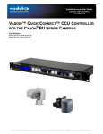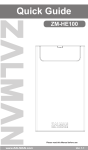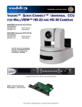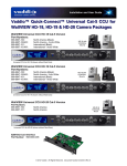
1
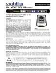
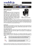
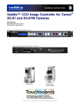
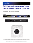
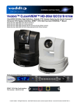
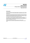
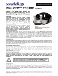
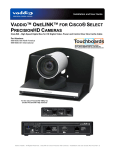
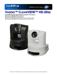
Installation and User Guide
Camera and Electronic Products for Integrators
WALLVIEW™ CCU HE100 WITH HSDS™
Vaddio™ Quick-Connect™ CCU System for the Panasonic® AW-HE100 PTZ Camera
OVERVIEW
The Vaddio WallVIEW CCU HE100 (Figure 1) is built for use with
the Panasonic AW-HE100 high definition PTZ Camera. Vaddio’s
HE-100 camera is designed for easier integration where the
standard Panasonic RS-422 control is converted to RS-232 for
operation with our complete line of ProductionVIEW PTZ camera
controllers and seamless switchers.
The Quick-Connect CCU HE100 allows the user to control the
color output of the camera’s image sensor, through both Red
and Blue Gain knobs Detail, as well as Iris and Gain levels, to
provide a higher quality image. In addition, there are also
Pedestal, Gamma and Chroma adjustments for added finetuning of the camera’s image. The system uses high speed
differential signaling (HSDS), an active transmission system that
delivers low-loss, high-quality video over CAT-5 cabling
distances up to 500’ (152.4m).
Figure 1: Quick-Connect CCU HE100
System with Camera (not included), Wall
Mount and EZIM CCU (behind camera)
The system is capable of high definition (HD) 1080i or 720p component video and has a simultaneous SD
composite video output. The AW-HE100 comes in either NTSC or PAL formats. The Quick-Connect CCU
for the HE-100 has many new features, including Tally illumination on the camera which allows the presenter
to know which camera is live, as well as Genlock delivered to the camera over CAT-5.
INTENDED USE
Before installing the Vaddio WallVIEW CCU Camera System, please read the entire manual thoroughly. All
Vaddio camera systems are designed for use indoors. Outdoor operation is not recommended, has not been
tested, and could damage the camera and/or create a potentially unsafe operating condition. Use only the
Vaddio PowerRite power supply provided.
SAVE THESE INSTRUCTIONS
The information contained in this manual will help you install the Vaddio WallVIEW CCU system. For
reference, Vaddio keeps copies of Specifications, Installation and User Guides and most pertinent product
drawings for the Vaddio product line on the website. These documents can be downloaded from
www.vaddio.com free of charge.
IMPORTANT SAFEGUARDS
Read and understand all instructions before using. Do not operate any electrical device if it has been
dropped or damaged. In this case, a Vaddio technician must examine the product before operating. To
reduce the risk of electric shock, do not immerse in any liquids and avoid extremely humid conditions.
Use only the approved power supplies provided with the system.
Use of any unauthorized power supply will void any and all
Do not use RJ-45 “pass-thru” connectors.
connectors for best results.
Use standard RJ-45
INFORMATION
For RS-422 control information, please see the full-length Manual for the PANASONIC AW-HE100 posted on
the Vaddio or Panasonic website. Vaddio has also prepared a number of TechNotes, specifications and
drawings designed to inform and educate integrators on the value and the specific uses of Vaddio products.
©2010 Vaddio - All Rights Reserved. Reproduction in whole or in part without written permission is prohibited. Specifications and
pricing subject to change. Vaddio, WallVIEW, HSDS, Quick-Connect, EZIM, ProductionVIEW, PreVIEW, EZCamera and PowerRite are
registered trademarks of Vaddio. All other trademarks are property of their respective owners. Document Number 341-789 Rev. B
WallVIEW CCU HE100
UNPACKING
Carefully remove and identify the following parts for the WallVIEW CCU HE100 system:
• One (1) Panasonic AW-HE100 – Modified 12 VDC Version - with IR Remote
• One (1) Quick-Connect CCU (998-1105-014) with 2-position Phoenix Type Connector
• One (1) CCU EZ Interface Module CCU (998-6700-002) EZIM CCU
• One (1) CCU HE100 25-pin Breakout Cable (440-6707-110)
• One (1) DB-9F to RJ-45F, RS-232 to RS-422 Adapter (998-1005-232)
• One (1) CommFront CVT-485_422-1 Port Powered RS-232 to RS-422 Converter
• One (1) 1’ Cat 5 Patch Cable
• One (1) Wall Mount AW-HE100 (535-2000-229) and Mounting Hardware
• One (1) 36V PowerRite Power Supply with AC Cord Set
• One (1) User Manual (341-789)
• Documentation
• Vaddio Manual
AW-HE100 Camera, Wall Mount
with EZIM CCU (behind camera)
• Panasonic Manual
HD Break-out
Cable
Wiring Diagram Example:
EZIM CCU
RS- 232 to
RS-422
Converter
RS-422
RS-232
DB-9 F to
Cat 5
POWER
DB-9M to RS-232 to 422 Converter, Cat 5 Adapter
SD VIDEO OUT
G/L
HD VIDEO OUT (Y, Pb, Pr)
CAT-5 Cables
up to 500’
Power
HD & SD (composite) Video on CAT-5
RS-232 & Gen Lock
Quick-Connect CCU
+ G
RS-232
Tally
Component HD
Composite
Video
SD Composite Video to
PreVIEW™ Monitors
ProductionVIEW™ HD
Figure 2: The Quick-Connect CCU System uses a Cat. 5 (all 4-pairs) for power to ensure the motors receive the
required current to operate properly. The Video Cat. 5 cable uses all four pairs for video. The RS-232 Cat. 5 provides
communication to the camera for CCU and PTZ control and G/L (where applicable) to the camera. These Cat. 5
cables can be run up to 500’ (152.4m). See Appendix 1 for wiring and pin-out information. NOTE: A direct RS-232
Cat. 5 cable is required for each Quick-Connect CCU and camera, with the RS-232 converted to RS-422 at the break
out cable. Daisy-Chain is not supported with the AW-HE100 camera.
Quick-Connect CCU HE100 Installation and User Guide 341-789 Rev. B
Page 2 of 12
WallVIEW CCU HE100
Quick-Connect CCU Front Panel Controls (left to right):
Tally Light:
The blue LED tally light on the front panel is tied to the tally contacts on the rear panel allowing the user to
easily track which camera interface is being used in a multi-camera system by supplying a simple contact
closure (i.e. from ProductionVIEW Super Joystick or ProductionVIEW HD).
LCD Display:
Backlit (blue) display indicates which mode is active (CCU CONTROL or PTZ CONTROL) and the value of
the parameter being adjusted. In CCU CONTROL mode, when a rotary encoder is touched, the name of the
control being actuated and the value of that assigned parameter will be displayed.
CCU Control Switch:
Backlit (blue) SPDT switch, lit when activated, blocks the incoming PTZ controls on the RS-232 input and
allows the end user to make adjustments to the camera image characteristics. When off or deactivated, PTZ
information is throughput to the camera and the front panel controls of the QCCU are deactivated to avoid a
control issue or latency created by a master control string filtering program.
Scene A and B:
Two camera adjustment scenes (A & B) can be stored into microprocessor memory. When lit (backlit blue
SPDT switch), the scene is activated. To store a scene, the user adjusts the controls and touches and holds
the scene button down until the button blinks.
Detail:
The Detail control sharpens or softens objects in the frame.
Red & Blue Gain Controls:
The Red and Blue Gain encoders adjust the red and blue gain of the signal when AWB is disengaged.
AWB:
The Automatic White Balance controls/adjusts the color levels automatically when engaged. Turn off AWB
to manually adjust the Red and Blue levels, as well as Red, Green and Blue Enhance.
OPWB:
One-Push White Balance control allows the user to set the white balance with one push (the camera must
see 60% of the image as white in order to operate). OPWB overrides AWB and Red/Blue controls when
activated.
Pedestal, Chroma & Gamma:
The Pedestal adjustment controls the absolute black level of an image. Chroma controls the overall color of
the image being captured. Gamma adjusts the overall brightness of an image.
Auto Iris:
The Auto Iris mode automatically adjusts the iris and gain of the camera. To manually adjust the iris or gain,
turn off this control.
Manual Iris:
The manual iris control allows the user to set the iris manual to one of the 18 settings available.
Gain:
The Gain control boosts the signal level when the iris is open all the way, and there is not enough lighting
available. To manually adjust the gain Auto Iris must be off.
Quick-Connect CCU HE100 Installation and User Guide 341-789 Rev. B
Page 3 of 12
WallVIEW CCU HE100
Rear Panel Connections and Controls (Left to Right):
+ G
Power Supply Input:
36V 2.78 Amp power supply on a 5.5mm OD x 2.5mm ID connector.
Power on RJ-45:
Power is provided on a Cat. 5 cable to EZIM CCU.
RS-232 IN on RJ-45:
RS-232 Input from ProductionVIEW or PTZ controller. Daisy Chain control is not supported.
RS-232 OUT / G/L Out on RJ-45:
RS-232 and G/L outputs on Cat. 5 provide control and sync to the EZIM CCU. NOTE: See Appendix 1 for
information on adjusting Genlock Gain on the EZIM.
Tally on 2-pin Phoenix type connector:
Contact Closure lights LED on front panel allowing indication of which QCCU/camera combination is active in
a multi-camera/QCCU installation. A tally command will also be sent to the camera to illuminate the LED on
the cameras that have on-board tally lights (AW Series cameras).
G/L Input on BNC-F:
For use with black burst generators to externally sync the cameras. This input is transmitted through a
differential amplifier to a receiver at the EZIM CCU. The G/L gain adjustment is on the EZIM CCU or the
receive side of the signal.
Camera Feature Switches:
The QCCU interface has an 8-position dip switch on the rear panel to allow future functionality. Switch 2
needs to be in the UP position for the AW-HE100 to function properly.
Y-Gain:
Adjusts Y-Gain and allows the user to fine tune the video signal especially over longer cable lengths. Adjust
to taste and system requirements.
Distance:
Distance Adjustments for Cat. 5 cable (<100’, 200’, 300’, 400’+) equalizes the length of the twisted pairs for
improved video performance.
Video Outputs:
Four Video Signals at any one time can be transmitted from the EZIM CCU concurrently allowing the CCU
system to return HD and SD (composite video on cameras with simultaneous outputs, such as the AWHE100) at the same time.
Connector Labels and Supported Video Signals
Y/Y:
Y of YPbPr - or - Y (luminance) of Y/C on BNC-F connector
PB/C:
PB of YPbPr - or - C (chrominance) of Y/C on BNC-F connector
PR:
PR of YPbPr only on BNC-F connector
COMP:
Composite (CVBS) Video on BNC-F connector
Video RJ-45
Return of the camera’s four (4) video signals from the EZIM CCU to the Quick-Connect CCU on Cat. 5 cable.
Quick-Connect CCU HE100 Installation and User Guide 341-789 Rev. B
Page 4 of 12
WallVIEW CCU HE100
INSTALLATION
All Quick-Connect products are specifically designed for installation on a vertical wall surface with CAT-5
cable connectivity for Power, Video and Control signaling. Installation is simplified in that no custom 8-Pin
mini-din cables or expensive VGA plenum cables are needed and no power outlets are required near the
camera bracket. All cabling is routed to the head-end using CAT-5 cables.
Before Installing
• Find the appropriate camera mounting location, paying close attention to camera viewing angles, lighting
conditions, possible line of site obstructions, and checking for in-wall obstructions where the camera is to
be mounted. Pick a mounting location to optimize the performance of the camera.
• Pre-wire all cabling as required (see wiring diagram examples).
• The Thin Profile Wall Mount for the WallVIEW HE100 can be mounted directly to a 3-gang wall box or
can be mounted to drywall using four dry wall anchors.
MOUNTING INSTRUCTIONS
Step 1:
After determining the optimum location of the camera system, mark locations for the four screw holes and
cable pass-thru (vertical oval). Install the drywall mounts and cut the hole for the cable pass-thru. At this
point, do not install the Wall Mount.
Figure 3:
\Wall Mount with oval cable feed-through hole.
The wall mount may be mounted directly to a 3gang wall box or to drywall with the appropriate
wall anchors.
Step 2:
Connect the 25-pin cable to the EZIM CCU. Next, mount the EZIM CCU and break out cable in the base of
the wall mount, using the two tapped screw holes (see Figure 4).
Figure 4:
25-pin connector mounted to
EZIM CCU (left) and EZIM
CCU mounted to the Wall
Mount (right).
Exact cable not shown see Appendix for cable
configuration.
Step 4:
Take the Wall Mount, with the EZIM CCU and break out cable installed, and place it against the drywall
anchors or 3-gang wall box, making sure to pull the CAT-5 cables through the oval pass-through hole.
Finger-tighten the screws to the mount and confirm that the base is level. Tighten the screws firmly. If the
bracket is to be mounted on a 3-gang wall box, use the screws supplied with the electrical box.
Quick-Connect CCU HE100 Installation and User Guide 341-789 Rev. B
Page 5 of 12
WallVIEW CCU HE100
Step 5:
Confirm that the CAT-5 cables are terminated correctly, by testing them with a continuity tester. Next,
connect the break out cables to the appropriate ports. The break out cable for the HE 100 has an RS-232 to
RS-422 adapter in-line, with a 1 ft. CAT-5 cable, which connects to the Controller port on the back of the
camera (see Figure 4). Secure the camera to the mount and using the ¼”-20 screws.
Step 6:
The Quick-Connect CCU interface has an 8-position dip switch on the rear panel (see page 4). Set Dip
Switch 2 to the UP position. All other switches should be in the DOWN position.
Description
Dip Switch (Up = ON)
1
Panasonic AW-HE100
•
Setting the #2 dip switch to the UP position allows Vaddio’s
ProductionVIEW controllers and switchers to recognize the camera.
2
3
4
5
6
7
8
DN
DN
DN
DN
DN
DN
UP
DN
Step 7:
The Quick-Connect CCU is a 1-RU rack mount interface that breaks out the signals from the Cat. 5 cables
back to the standard connectors. The basic system connectivity is illustrated in Figure 2.
Note: Plugging the POWER CAT-5 Cable into the wrong RJ-45 may cause damage to the camera system and
void the warranty.
COMPLETING THE INSTALLATION:
Connect the Vaddio 36 VDC power supply to an AC outlet. Power will travel down the Power CAT-5 cable to
the cable shoe, powering the camera. The camera will “Home” to a centered position ready for control
information from the provided IR Remote Commander or RS-232 Camera controller of the integrators’ choice.
To insure proper continuity of control and operation of the cameras, the RS-232 controller (control system or
joystick) should be powered on after the camera.
Setting Up the AW-HE Video Format and Output Settings:
The CCU system is capable of accessing the HE 100s internal settings for format (1080/59.94i, 720/59.94,
480i, etc.) and output mode (YPbPr, RGB, Y/C). Once the camera and CCU are powered up, the
configurations can be set. The procedure is as follows:
The camera setup state is triggered by holding down the AWB and OPWB buttons on the Quick-Connect
CCU at the same time for approximately 5 seconds. The lights will blink when the setup mode is entered
and “Format/Output” will be displayed on the LCD screen of the CCU. Once the “Format/Output” is
displayed, adjusting these settings can begin.
Camera Picture Format Adjustment: Turn the Pedestal knob on the Quick-Connect CCU to scroll through
the format options of the camera, which range from 480/29.97psF to 1080/30p. Once the appropriate
resolution is displayed on the LCD screen, this is the setting that will be saved. NOTE: Not all of the
resolution options on the HE 100 will be recognized by the receiving device (ProductionVIEW HD or HD
video monitor, etc.), so be sure to select an appropriate resolution for your external device that is connected
to the Quick-Connect CCU.
Press the Auto Iris button to save the setting and “Format Saved” will be displayed on the LCD screen.
Camera Output Mode: Turn the Chroma knob on the Quick-Connect CCU to scroll through the output
options, which are RGB, YPbPr and Y/C. Once the appropriate output mode is displayed on the LCD screen,
this is the setting that will be saved (NOTE: Use only YPbPr with the Quick-Connect CCU).
Press the Auto Iris button to save the setting and “Output Saved” will be displayed on the LCD screen.
Quick-Connect CCU HE100 Installation and User Guide 341-789 Rev. B
Page 6 of 12
WallVIEW CCU HE100
Setting the Format and Output Settings (continued):
NOTE: Only values that are valid for the specific camera firmware will be saved. Confirmation of the format
or output saved can be verified by turning the Pedestal or Chroma knobs.
Exiting Camera Setup Mode: Exiting this configuration mode is done by pressing either the AWB or OPWB
button on the Quick-Connect CCU. “Exit Setup” is displayed on the LCD screen when either button is
pressed.
All of the cameras Format and Output settings can be accessed with the Panasonic IR Remote Control.
Connecting the Tally Port (optional)
The CCU system is capable of illuminating a Tally light on the front of the Quick-Connect enclosure. This
light provides a visual indicator to the equipment operator to know which camera is live during a broadcast.
In addition the tally function will illuminate the tally light on the front of the camera lens, to allow the presenter
to know which camera is live.
General Specifications
WallVIEW CCU HE100
Part Numbers
•
Panasonic AW-HE100
Image Device
Signal System
Lens
Focal Length
Horizontal Viewing Angle
Pan/Tilt Angle
WallVIEW CCU HE100
WallVIEW CCU HE100
999-6107-000 (NTSC)
999-6107-001 (PAL)
1/3” CCDs x 3
N: 1080/59.94i, 720/59.94p, 480i,
P: 1080/50i, 720/50p, 576i
13x Optical Zoom
f=4.2 to 55mm
5.1 to 60 degrees (16:9); 3.8 to 47 degrees (4:3)
-175 to +175 degrees (Pan), -40 to +210 degrees (Tilt)
•
Quick-Connect CCU Interface (QCCU)
Connectors
Power Connector: 5.5mm OD x 2.5mm ID
Power RJ-45: Supplies 36V to EZCamera Interface Module Regulator
Control In RJ-45: Accepts RS-232 from ProductionVIEW or other non-daisy-chain control systems
Control Out RJ-45: Passes RS-232 and Sync video feed to camera EZIM
Tally: 2-Pin Phoenix type spring cage connector
G/L Input: BNC Connector for Sync
Video Outputs: BNC Connectors for HD Analog Component (Y,PB,PR) / SD (Composite)
Video RJ-45: Transports HD video from camera EZIM
Camera Select Switch
Dip Switch 2 UP for WallVIEW CCU HE100 (the rest remain down)
Video Adjustments
Y-Gain (luminance gain) for fine tuning over longer cable distances
Distance Compensation: 100’, 200’, 300’, 400’+
CAT-5 Cable Distance
Up to 500’ (152.4m)
Power Supply
36 VDC, 2.78 Amp
Dimensions
1-RU Rack Mount - 1.75” H x 19” W x 6” D (4.45 cm x 4.26 cm x 15.24 cm)
•
EZCamera Interface Module CCU (EZIM)
Connectors
Three (3) RJ-45 Connectors
One DB-25 for Power, Video, Control & Genlock
EZIM CCU Cable
For Panasonic HE100 Camera: DB-25M to DB-15HD, DB-9 to RJ-45, BNC x 2, 4-Pin XLR-F Power
Assembly
Connector PN# 440-6707-110
Power Regulator
Supplies 12VDC to Cameras
Dimensions
3” H x 4.5” W x 1.2” D (7.6 cm x 11.4 cm x 3 cm)
•
Thin Profile Wall Mount HE100
Materials
12-Gauge CRS with Black Powder Coat Paint
Dimensions
8” H x 8.5” W x 13.5” D (20.3 cm x 21.6 cm x 34.3 cm)
Weight
Approx. 6 lbs. (2.7kg)
Quick-Connect CCU HE100 Installation and User Guide 341-789 Rev. B
Page 7 of 12
WallVIEW CCU HE100
FCC, ICES-003 Compliance and CE Declaration of Conformity
For Vaddio Quick-Connect CCU and EZIM CCU products
FCC Part 15 Compliance
This equipment has been tested and found to comply with the limits for a Class A digital device, pursuant to
Part 15 of the FCC Rules. These limits are designed to provide reasonable protection against harmful
interference when the equipment is operated in a commercial environment. This equipment generates, uses,
and can radiate radio frequency energy and, if not installed and used in accordance with the instruction
manual, may cause harmful interference to radio communications. Operation of this equipment in a
residential area is likely to cause harmful interference in which case the user will be required to correct the
interference at his/her own expense.
Operation is subject to the following two conditions: (1) This device may not cause interference, and (2) This
device must accept any interference including interference that may cause undesired operation of the device.
Changes or modifications not expressly approved by Vaddio can affect emission compliance and could void
the user’s authority to operate this equipment.
ICES-003 Compliance
This digital apparatus does not exceed the Class A limits for radio noise emissions from digital apparatus set
out in the Radio Interference Regulations of the Canadian Department of Communications.
Le présent appareil numérique n’emet pas de bruits radioélectriques dépassant les limites applicables aux
appareils numeriques de la classe A préscrites dans le Règlement sur le brouillage radioélectrique édicte par
le ministère des Communications du Canada.
European Compliance
This product has been evaluated for Electromagnetic Compatibility under the standards for Emissions and
Immunity and meets the requirements for E4 environment. This product complies with Class A (E4
environment). In a domestic environment this product may cause radio interference in which case the user
may be required to take adequate measures.
Standard(s) To Which Conformity Is Declared:
EMC Directive 89/336/EEC
EN 55022A
Conducted and Radiated Emissions
EN 55024
Electromagnetic Compatibility - Immunity
EN 61000-4-2
Electrostatic Discharge Requirements
EN 61000-4-3
Radiated Electromagnetic Field Requirement
EN 61000-4-4
Electrical Fast Transients / Burst Requirements
EN 61000-4-5
Surge Requirements
EN 61000-4-6
Conducted Immunity Requirements
EN 61000-4-8
Power Frequency Magnetic Field Requirements
EN 61000-4-11
Voltage Dips, Interrupts and Fluctuations Requirements
Quick-Connect CCU HE100 Installation and User Guide 341-789 Rev. B
Page 8 of 12
WallVIEW CCU HE100
Appendix 1: Cable Pin-outs for the Quick-Connect CCU System
Quick-Connect CCU Pin-out Assignments:
POWER
CONTROL & EXT. SYNC
CAMERA
VIDEO ADJUST
VIDEO OUTPUTS
VIDEO
200 300
400+
>100
36V
2.78A
RS-232 IN
RS-232 OUT
G/L OUT
Power Connector RJ-45
Signal
Pin
1)
Power +
2)
Power 3)
Power +
4)
Power 5)
Power +
6)
Power 7)
Power +
8)
Power -
G/L INPUT
CAM SELECT
Y-GAIN
DISTANCE
Y
Y
PB
C
PR
COMP
12345678
RS-232 IN Connector RJ-45
Signal - RS-232
Pin
1)
Not Used
2)
Not Used
3)
Not Used
4)
Not Used
5)
Not Used
6)
GND
7)
RXD (from TXD)
8)
TXD (to RXD)
12345678
RS-232 / G/L OUT Connector RJ-45
Signal - RS-232
Pin
1)
Not Used
2)
Not Used
3)
Not Used
4)
G/L
5)
G/L GND
6)
GND
7)
RXD (from TXD)
8)
TXD (to RXD)
Video Connector RJ-45
Signal
Pin
SD
1)
CVBS +
2)
CVBS GND
3)
Y+
4)
C+
5)
C GND
6)
Y GND
7)
Not Used
8)
Not Used
TALLY
GND +
HD
CVBS +
CVBS GND
Y+
PB+
PB GND
Y GND
PR+
PR-
12345678
12345678
Quick-Connect CCU HE100 Installation and User Guide 341-789 Rev. B
Page 9 of 12
WallVIEW CCU HE100
EZIM CCU Pin-out Assignments
Power Connector RJ-45
Signal
Pin
1)
Power +
2)
Power 3)
Power +
4)
Power 5)
Power +
6)
Power 7)
Power +
8)
Power -
EZIM
CCU
12345678
EZIM DB-25 Connector
Signal
Pins
1
CVBS GND
14
CVBS
2
G/L GND
15
G/L
3
NC
16
GND IN
4
TXD IN
17
RXD IN
5
NC
18
NC
6
NC
19
NC
7
GND - PR
20
PR
8
GND - C/PB
21
C/PB
9
GND - Y/Y
22
Y/Y
10
GND - PWR
23
GND - PWR
11
GND - PWR
24
12V - PWR
12
12V - PWR
25
12V - PWR
13
12V - PWR
G/L
GAIN
RS-232 IN/ VIDEO
G/L IN
Genlock Gain Adjustment:
Genlock Gain is set at the factory
to the 3 o’clock position, which
provides standard blackburst
level. Adjust the gain level up or
down if required to synchronize
the camera to other devices.
RS-232 IN Connector
Signal - RS-232
Pin
1)
Not Used
2)
Not Used
3)
Not Used
4)
G/L+
5)
G/L GND
6)
GND
7)
RXD (from TXD)
8)
TXD (to RXD)
Video Connector RJ-45
Signal
Pin
SD
1)
CVBS +
2)
CVBS GND
3)
Y+
4)
C+
5)
C GND
6)
Y GND
7)
Not Used
8)
Not Used
POWER
12345678
HD
CVBS +
CVBS GND
Y+
PB+
PB GND
Y GND
PR+
PR-
12345678
EZIM CCU Breakout Cable for
WallVIEW CCU HE100
PN# 440-6707-110
POWER - XLR 4-Pin F
CONTROL DB-9 M
CVBS VIDEO - BNC
G/L - BNC
DB-25 M Connector
HD VIDEO - DE-15 M
(D-Sub 15-pinHD M)
Quick-Connect CCU HE100 Installation and User Guide 341-789 Rev. B
Page 10 of 12
WallVIEW CCU HE100
WARRANTY INFORMATION
Hardware* Warranty - One year limited warranty on all parts. Vaddio warrants this product against defects
in materials and workmanship for a period of one year from the day of purchase from Vaddio. If Vaddio
receives notice of such defects during the warranty period, they will, at their option, repair or replace
products that prove to be defective.
Exclusions - The above warranty shall not apply to defects resulting from: improper or inadequate
maintenance by the customer, customer applied software or interfacing, unauthorized modifications or
misuse, operation outside the normal environmental specifications for the product, use of the incorrect power
supply, improper extension of the power supply cable or improper site operation and maintenance.
Vaddio Customer service – Vaddio will test, repair, or replace the product or products without charge if the
unit is under warranty and is found to be defective. If the product is out of warranty, Vaddio will test then
repair the product or products. The cost of parts and labor charge will be estimated by a technician and
confirmed by the customer prior to repair. All components must be returned for testing as a complete unit.
Vaddio will not accept responsibility for shipment after it has left the premises.
Vaddio Technical support - Vaddio technicians will determine and discuss with the customer the criteria for
repair costs and/or replacement. Vaddio Technical Support can be contacted through one of the following
resources: e-mail support at [email protected] or online at www.vaddio.com.
Return Material Authorization (RMA) number - Before returning a product for repair or replacement,
request an RMA from Vaddio’s technical support. Provide a technician with a return phone number, e-mail
address, shipping address, and product serial numbers and describe the reason for repairs or returns as well
as the date of purchase and proof of purchase. Include your assigned RMA number in all correspondence
with Vaddio. Write your assigned RMA number on the shipping label of the box when returning the product.
Please see Vaddio’s website for current RMA policies and procedures.
Voided warranty – The warranty does not apply if the original serial number has been removed or if the
product has been disassembled or damaged through misuse, accident, modifications, or unauthorized repair.
Cutting the power supply cable on the secondary side (low voltage side) to extend the power to the device
(camera or controller) voids the warranty for that device.
Shipping and handling - Vaddio will not pay for inbound shipping transportation or insurance charges or
accept any responsibility for laws and ordinances from inbound transit. Vaddio will pay for outbound shipping,
transportation, and insurance charges for all items under warranty but will not assume responsibility for loss
and/or damage by the outbound freight carrier. If the return shipment appears damaged, retain the original
boxes and packing material for inspection by the carrier. Contact your carrier immediately.
Products not under warranty - Payment arrangements are required before outbound shipment for all out of
warranty products.
*Vaddio manufactures its hardware products from parts and components that are new or equivalent to new in accordance with industry
standard practices.
CARE AND CLEANING
•
Do not attempt to take the products in the system apart. There are no user-serviceable components.
•
Keep the devices away from food and liquid, and do not spill liquids on the products.
•
For smears or smudges on the lens, wipe with a clean, soft cloth. Do not use any abrasive chemicals on the camera
body at any time.
OPERATING AND STORAGE CONDITIONS
Do not store or operate the Quick-Connect CCU System under the following conditions:
•
Temperatures above 40°C (104°F) or below 0°C (32°F), for Indoor Use Only
•
High humidity, condensing or wet environments
•
Dusty environments
•
In inclement weather
•
Under severe vibration
Quick-Connect CCU HE100 Installation and User Guide 341-789 Rev. B
Page 11 of 12
WallVIEW CCU HE100
9433 Science Center Drive, Minneapolis, MN 55428
Toll Free: 800-572-2011 ▪ Phone: 763-971-4400 ▪ FAX: 763-971-4464
www.vaddio.com
©2008 Vaddio - All Rights Reserved. Reproduction in whole or in part without written permission is prohibited. Specifications and pricing
subject to change. Vaddio, Quick-Connect, HSDS, Quick-Connect, EZIM, ProductionVIEW, PreVIEW, EZCamera and PowerRite are
registered trademarks of Vaddio. All other trademarks are property of their respective owners. Document Number 341-789 Rev. B
Quick-Connect CCU HE100 Installation and User Guide 341-789 Rev. B
Page 12 of 12