1
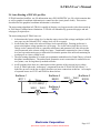
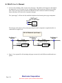
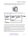
E-TRAN User’s Manual 9 Theory of E-TRAN E-TRAN bridges the gap between phasor based loadflow and stability simulation tools and electromagnetic transient (EMT) tools. E-TRAN internally solves the steady state phasor equations and uses this information to initialize a PSCAD/EMTDC circuit, as well as to form network equivalents to reduce the network so it is suitable for transient analysis. The steady state solution in PSCAD/EMTDC is based on the solution of instantaneous differential equations (of either single phase or three phase circuits), whereas the solution in PSS/E or loadflow programs is based on phasor based complex variable calculations at the fundamental frequency. The steady state solutions for the two methods match to a very high degree of accuracy, which gives the user confidence that the conversion process and network equivalents has been done properly. The loadflow information (obtained from the loadflow input files) is used by E-TRAN to directly initialize the circuit in PSCAD/EMTDC (including sources in the network equivalents and generators). Finally, E-TRAN will auto-route the circuit (based purely on the raw connection and bus information) so as to create a PSCAD graphical circuit which can be visualized on the screen. The theory behind each of these E-TRAN technologies is discussed in the following sections in this chapter. Electranix Corporation Specialists in power system studies and simulation Page 9-1 E-TRAN User’s Manual 9.1 Network Equivalents E-TRAN can be used to translate very large systems (defined in loadflow .raw files) into PSCAD, suitable for electro-magnetic transient analysis. Although the PSCAD EMT tool is capable of simulating very large systems (3,000 busses and higher, limited only by memory), practically users must limit their study scope and introduce network equivalents at the boundaries of their simulation network. One decision a user must make is where should a network equivalent be placed (ie how many busses away from the area of interest)? The system represented in detail (ie the “kept” network) will give a more accurate frequency response (particularly if the data is updated with detailed frequency dependant transmission lines, transformers with saturation etc…) compared to the system in the network equivalent (which is based on fundamental frequency). It is difficult to define the system equivalent boundary, but be sure to represent all the “dominant” electrical devices in the “kept” network (such as machines, nonlinearities…) and try to place the system equivalent at least 2 or more busses away from the area of interest. The more of the system that is represented in detail, the more accurate the representation will be. A commonly used simple method of generating network equivalents is to insert a voltage source behind impedance at every boundary bus to represent the PQ flow into the portion of the network at that bus (this is known as a 1 port equivalent). The sources are often represented with series RL source impedances (based on the fundamental frequency short circuit capacity or short circuit impedance). This method will give the correct power flow in steady state, but will not give the correct open circuit or short circuit response. What is missing in this simple form of a network equivalent is the “off-diagonal” impedance terms which represent the interconnections in the non-kept portion of the network (ie from one boundary bus to another). What is required (to get steady state, short circuit and short circuit impedances correct) is an N-port equivalent. E-TRAN calculates a N-port network equivalent based on the fundamental frequency impedances of the system. The equivalent includes both diagonal and off-diagonal terms, and is valid for steady state, open circuit and short circuit conditions. In order to create the most accurate network equivalent possible, E-TRAN recomments that the “Machine impedance ZSORCE” data be entered for all generators. This data is not used nor required for normal loadflow studies, but it is essential to create accurate network equivalents. - If the ZR, ZX generator data is entered: o If the generator is in the network to be equivalenced, then it will be reflected in the impedance elements of the equivalent that E-TRAN creates. o If the generator is in the kept network, this impedance will be used in the series impedance of the generator voltage source. - If the ZR, ZX generator data is not entered: o If the generator is in the network to be equivalenced, then the network equivalent will not contain the most accurate impedance information. In this case, the generator fundamental frequency PQ flow information will be represented entirely in the voltage source magnitude and phase terms of the network equivalent. o If the generator is in the kept network, the generator will be represented as an infinite bus at its terminals. Electranix Corporation Specialists in power system studies and simulation Page 9-3 E-TRAN User’s Manual E-TRAN forms the N-port network equivalent using the following steps: - Form Yfull, the complex Admittance Matrix (Y) of the entire system. Yfull includes all branches, generators, loads (all types), switched shunts, dc links, shunt admittances… at the correct operating point based on the loadflow solution. - Compute the solution PQ mismatch. The loadflow bus voltage magnitude and angle are used to calculate the voltage and current flow at all generation/load busses, and to determine the PQ flow mis-match. Since the loadflow program uses an iterative process to determine the steady state bus voltage magnitudes and angles, the result is never 100% correct and a small mis-match always exists. E-TRAN calculates the mis-match to ensure the loadflow solution read in is valid. The top 6 busses with the maximum PQ mis-match is written to the translation log file (see Note 1 below). - Calculate Yreduced, which is Yfull reduced down to the N kept nodes that the user has defined. The reduction process is performed by a complex, sparse LDU decomposition routine. The matrix algebra used in E-TRAN includes: o support for ideal branches (ie 0.0 resistance branches), including series combinations and loops… o non-symmetric admittance matrices (which will occur when phase-shifters are included in a network to be equivalenced). o System matrices of any size (the algorithm is 100% auto-dimensioning and automatically allocates and de-allocates system memory as it requires). - Form Ykept, which is the partial admittance matrix for system defined within the N kept busses. - Calculate Yequiv, which is Yreduced – Ykept. This admittance matrix represents all network branches and impedances in the network equivalent. - Ykept is then decomposed into actual circuit elements in the PSCAD page: o Off-diagonal elements are represented with PI sections (if the busses at each end are equal) or as transformers (if the bus voltages at each end are different). o Diagonal elements (formed after the off-diagonal admittances have been removed) are represented by voltage sources behind impedances (the voltage source magnitude and phase are also automatically calculated as described below). o The admittance elements are processed by comparing them to a user selectable limit (which optionally can be used to reduce the size of the meshed network equivalent) and are checked for negative impedance values (see Notes 2 and 3 later in this section). - Calculate the PQ flow in all the diagonal source impedance elements in the network equivalent. These are used to automatically set the voltage source magnitude and phase in the network equivalent (which represent the quasi-diagonal elements). Page 9-4 Electranix Corporation Specialists in power system studies and simulation E-TRAN User’s Manual Yfull:= Ykept := -----> LDU Decomposition ----> Yreduced := Yeq := Yreduced − Ykept Yeq := The kept circuit and the network equivalent is then auto-routed (see Section 9.4) and a PSCAD .psc file is output ready to run. The resulting simulation matches the loadflow solution to a very high degree of accuracy (typically 3 or 4 decimal points – see Section 9.2) and will give the correct open circuit and short circuit solutions (this is not possible with simple 1 Port equivalents). The procedure described above is valid for an equivalent of any size. It can be applied for a network which reduces down to a single boundary bus, to a system without any equivalents, or to a system with 1000+ busses in the kept network. Since E-TRAN uses dynamic memory allocation for all internal variables, the limits may be due to the amount of computer memory and processing time. Electranix Corporation Specialists in power system studies and simulation Page 9-5 E-TRAN User’s Manual Notes: 1) The system PQ mis-match is calculated and output to the log file for the 6 busses with the largest mis-match values. As an example, the output will appear as follows: ** The busses with the largest PQ errors (p.u. on 100 MVA) are: Bus: 6690, (P,Q) = (0.000254857,-0.0108962) Bus: 6395, (P,Q) = (-0.000406286,0.0107969) Bus: 6525, (P,Q) = (0.00335256,0.00388231) Bus: 6580, (P,Q) = (-0.00100919,-0.00486241) Bus: 6515, (P,Q) = (-0.0033093,-0.00326677) Bus: 6535, (P,Q) = (0.000947345,0.00445447) Note that you may see cancelling mis-matches that are +ve and –ve for busses at either end of a branch which has a very small impedance. This is due to the finite resolution (4 digits of accuracy) which is used to write the bus voltages and phase angles to the .raw loadflow file. The power flow through a branch is V1*V2*Sin(Angle1-Angle2)/X, so if X is very small, Angle1 and Angle 2 will be very close together and the difference between them will show large numerical errors. If X is exactly 0.0 (or less than 0.0001 PU), then this is handled by the ideal matrix reduction algorithm, in which case the problem does not occur. 2) The “Eq Admittance Limit” parameter (see Options and Preferences in Chapter 5) can optionally be used to ignore very small admittances (which represent very weak connections between busses in the equivalent). If this option is used, then the equivalent can ignore offdiagonal terms whose admittance is less then the limit. The PQ flow in the network equivalent (which is used to calculate the equivalent voltage source magnitudes and phases) is adjusted accordingly so the system steady state solution will be correct. Note that using the “Eq Admittance Limit” option is an approximation and will result in a circuit that will not yield the correct open circuit and short circuit powerflows. In an extreme case, the “Eq Admittance Limit” parameter can be set very large, in which case all offdiagonals in the network equivalent are ignored, and the result is N simple 1 Port equivalents (discussed earlier). This feature may be useful where limited size network equivalents must be realized for use in realtime applications. 3) During the execution of E-TRAN, the user is presented with an option entitled “Convert –ve Impedances in Eq Network to +ve” (see Translation Options in Chapter 4.3.2). Negative impedances can occur in the equivalent network and are perfectly valid (and stable) in a phasor solution, but may not be realizable or stable in time domain EMT simulation. For example, in the time domain, a +ve R and –ve L in series will produce a exponentially growing unstable current if excited by a current source, but in the phasor domain will produce a steady state solution in a phasor solution. These options can be used to convert the –veX to a +ve X, which is stable and valid in the time domain. The PQ flows and voltage source terms that represent the network equivalent diagonals are automatically adjusted when this option is applied. Page 9-6 Electranix Corporation Specialists in power system studies and simulation E-TRAN User’s Manual 9.2 Matching the Loadflow in PSCAD The loadflow solution is based on complex linear algebra involving the fundamental frequency phasor solution of an electrical network (ie V(w) = I(w) . (R + j*w*L) ). The solution is obtained by iteration, with a given convergence criteria. Electromagnetic Transients (EMT) programs (such as PSCAD/EMTDC) solve differential equations for the electrical network (ie V(t) = R.I(t) + L.dI/dt ). The EMT solution method solves these differential equations by applying trapezoidal integration, which converts the differential equation into a difference equation (ie Y(t) is a function of X(t), X(t-delt), Y(t-delt)…). This integration process results in a direct matrix solution (ie no iterations and no iterations), but introduces an integration error (which can show up at very high frequencies). The error can be minimized by selection of an appropriate time step which depends on how high of a frequency response the simulation results will be required. A general rule of thumb is that a 50 uSec time step is suitable for frequencies up to 2 kHz. The solution at 50 Hz (or 60 Hz) will be quite accurate and the two solution methods should match to within 3 or 4 decimal points. If there is a discrepancy, this is generally due to an error in the representation of the device in one of the programs (such as a wrong load characteristic etc…) rather than due to en error in the solution method. An easy test in EMT programs is to reduce the time step (say from 50 uSec to 10 uSec) and see if the solution has changed. The E-TRAN library of components in PSCAD has been extensively tested by direct comparison against solved loadflow solutions. Each component has been first verified individually, and then the entire electrical network solution is compared to the loadflow solution. If you do see differences in the two solutions, ensure your measurements are extracting fundamental frequency, +ve sequence quantities. The EMT program can generate distorted waveforms (due to transformer saturation , DC links, resonances…), which can result in differences. The EMT program transmission line models can also introduce –ve and 0 sequence quantities due to non-transposed conductors, which can also generate differences. The E-TRAN measurement models (see Chapter 8.9) extract the +ve sequence fundamental frequency quantities, so these results should compare well. If you use your own measurement components (such as RMS etc…) then you may get different results. Electranix Corporation Specialists in power system studies and simulation Page 9-7 E-TRAN User’s Manual Finally, the transmission line data in the loadflow file contains only RXB information, which is not suitable for using the frequency dependant transmission line models in PSCAD/EMTDC. If more detailed line models are required, the user must re-enter detailed line constants information (such as the line geometry, ground resistivity…). The PSCAD/EMTDC line constants routine may not generate exactly the same +ve sequence impedances and admittances (as the RXB entered in the original loadflow), which can introduce a steady state error. It is therefore recommended that the loadflow RXB data (in the .raw file) be updated based on the PSCAD/EMTDC Line Constants solution at the fundamental frequency (this information is output in the linename.out file and accessed by the View->Output File command on a Tline sub-page. The PSCAD/EMTDC line data is output for an incremental length of line, in ohms or mhos (ie not PU) and is not corrected for longline effects. In PI sections (or loadflow) representations of lines, the line RXB data should be corrected for longline effects, in which case you must perform the following calculations: Enter RXB (+ve and 0 Seq) , not corrected for longline effects: R1 := 3.50440834 R0 := 30.0353808 Zbase Zbase X1 := 42.4153077 X0 := 114.340136 Zbase Zbase B1 := .000272598288 B0 := .000193555082 Ybase Ybase Z1 := R1 + X1⋅j Z0 := R0 + X0⋅j Perform longline corrections: γ1 := ( R1 + X1⋅j ) ⋅B1⋅j Z1_LL := Z1⋅ sinh( γ1) γ1 γ1 2 tanh B1_LL := B1⋅ γ1 2 γ0 := ( R0 + X0⋅j ) ⋅B0⋅j sinh( γ0) Z0_LL := Z0⋅ γ0 γ0 2 tanh B0_LL := B0⋅ γ0 2 where: - Zbase is VLL*VLL/100 MVA and Ybase is 1/Zbase. - R1,X1,B1… (calculated above are ohms/mhos for the entire length of line) Page 9-8 Electranix Corporation Specialists in power system studies and simulation E-TRAN User’s Manual 9.3 Initialization of Generators/Machines in PSCAD E-TRAN directly initializes the circuit model (and network equivalent) in PSCAD/EMTDC so that the bus voltages, angles, PQ flow … match the loadflow. The source/generator component (see Chapter 8.4) is by default a fundamental frequency voltage source and does not model machine swings or electro-mechanical oscillations. In order to model the machine in more detail, you must perform the following steps: - Replace the E-TRAN generator/source model with a detailed machine component (from the PSCAD Master Library) - Copy the initial terminal voltage magnitude, angle and PQ flow from the E-TRAN component to the PSCAD Master Library machine model. Note the PSCAD Master Library synchronous generator model requires the line to ground voltage (LL voltage / sqrt(3)) and the . It also requires the bus voltage angle to be entered in radians (not degrees) in the Initial Conditions parameter page. - Check the generator transformer. All E-TRAN generated transformers are wye-wye, but often generator transformers are wye-delta. If this is the case, you should replace the E-TRAN transformer with the PSCAD Master Library transformer (enter the wye-delta winding configuration, either leading or lagging delta). - If you did change the transformer configuration with a delta winding, then you must also add 30 degrees (if the delta is on the machine side and lags the wye) or subtract 30 degrees (if the delta is on the machine side and leads the wye) from the phase angle of the bus terminals of all generator/source devices connected on the delta side (note that the load components etc… only require the initial terminal voltage magnitude, not the phase, so they are unaffected). - Enter exciter, governor, turbine, stabilizer data etc… (refer to the PSCAD Master Library Machines sub-page). If you do not find the control circuit component you require, then contact [email protected] to see if the required model is available. The initialization process of machine models/controls in PSCAD/EMTDC is automated once the initial bus voltage magnitude and phase angle is available (which E-TRAN generates). The machine initialization process in PSCAD/EMTDC is summarized below: --------------------------------------------------------------------------------------------PSCAD Machine Model - Initialization --------------------------------------------------------------------------------------------1) From your loadflow program (or E-TRAN output), you require: - The voltages at each machine terminal (magnitude and phase) - The PQ flow into the machine terminals 2) Enter the V mag,phase into the Machine component. If your machine uses a wye-delta transformer (this is usually the case), then you have to take the load flow angles and subtract 30 degrees (if the delta lags the wye) or add 30 degrees (if the delta leads the wye) before you enter it into the machine (this is because the loadflow treats all transformers as wye-wye without phase shifts) (also be careful as the machine component initial conditions data requires entry of the machine angle in radians). Electranix Corporation Specialists in power system studies and simulation Page 9-9 E-TRAN User’s Manual 3) Have the machine component start as an ideal voltage source. This is done by using the machine parameter called "Source to Machine Transition". Enter a variable here (such as "S2M"), and then create a controls signal on the same page which creates an integer which is 0 until 0.5 seconds, and then switches to 1 for the duration of the run. This will force the EMTDC machine model to start as a voltage source (it is ramped to avoid transients), thus bypassing the mechanical and electrical dynamics. At 0.5 seconds the AC system should have stabilized and you should see the loadflow voltages and PQ flow matching everywhere in your system (you should get 4 decimal points matching if everything is correct). Matching the loadflow gives you a lot of confidence in the large amounts of data you have entered. If the loadflow does not match, then either the loadflow was not solved, or the PSCAD representation of each device is not the same as the loadflow representation. Common problems are: - the transformer impedance in the loadflow is entered in PU on a 100 MVA base, whereas you may be using a different MVA base when you enter the data into PSCAD - check the fundamental positive sequence impedance of transmission lines and cables and see if they match the RXB from the loadflow. You may want to first run your system with pi sections (with manual entry of RXB from the loadflow) and then switch to the fre-dep phase domain model later. - The PSS/E program assumes all RXB data is long-line corrected (as it uses it directly in a PI section formulation in its Y matrix). For short lines, the correction is a very minor effect and can be ignored. If you use this same data in a single PI section in PSCAD, then this should give the identical result. If you use the RXB data in a Bergeron model, then check the option that says the data is long-line corrected. - check load models - most loadflows have constant power, current, impedance or RLC loads (see comments on load models available with E-TRAN below) so if you are using a constant RLC load representation you have to calculate the RLC values based on the solved loadflow voltage level... When the S2M signal becomes 1, this forces the machine to measure the PQ flow into its terminals and to initialize the electrical circuitry internal to the machine. You should not see a bump during this transition. If you have power electronics in your circuit (such as HVDC etc...) then you may want to run for longer than 0.5 seconds until the entire system has reached steady state. The machine at this point is running with full electrical dynamics, but it is still ignoring the field input (from the exciter) and the torque input (from the governor) and is locked at steady state frequency (but at the correct rotor angle). 4) The next step is to get the exciter, governor, turbine, multi-mass models (if used) etc... to initialize and fully release the machine. This is done by using the "Lock Rotor to Normal Machine Transition" variable in the machine component. You can enter a variable here (such as "L2N") and then create a controls signal on the same page which creates an integer which is 0 until 0.6 seconds, and then switches to 1 for the duration of the run. This will force the EMTDC machine model to fully initialize and release all dynamics at 0.6 seconds. At the S2M transition, the machine model will: Page 9-10 Electranix Corporation Specialists in power system studies and simulation E-TRAN User’s Manual - calculate and output the electrical torque + damping torque (which is the initial mechanical torque) and pass this to the governor/turbine/multi-mass models. The governor/turbine/multi-mass models will use the initial mechanical torque and will back-initialize its control systems. You may see a small bump at this point if your system has any -ve sequence components of voltage or current. This can occur when you have unbalanced (non-ideally transposed) transmission lines or unbalanced loads. The -ve sequence component results in a small second harmonic on the field, which will show up on the electrical torque. Thus the initialization time point-on-wave might introduce a small second harmonic oscillation (which will be there in steady state) which cannot be avoided. 5) The machine is fully released at this point and the system should be ready for faults etc... You can look at your circuit and adjust the times for the source to machine transition (0.5 sec) and lock rotor to normal mode transition (0.6 sec) to suit your circuit. 6) If you do not have a loadflow program (so you do not know the voltage magnitude and angles), then you can run the PSCAD circuit once for a very long time (maybe 10-20 seconds or until all mechanical oscillations damp out), and then use the measured steady state information at the end of the run to set up the initial conditions. --------------------------------------------------------------------------------------------- Electranix Corporation Specialists in power system studies and simulation Page 9-11 E-TRAN User’s Manual 9.4 Auto-Routing of PSCAD .psc files E-TRAN translates loadflow .raw file information into a PSCAD/EMTDC .psc file, which contains data as well as graphical coordinate information (to control how the circuit picture looks). This section describes how the graphical coordinate information is calculated. The auto-routing algorithm in E-TRAN is capable of drawing very large networks (it has been tested up to 50,00 busses) with no known limitations. E-TRAN will automatically generate sub-pages and subsub-pages (if required) etc... The auto-routing steps E-TRAN uses are: 1. It determines the lowest voltage level so that the entire circuit of this voltage (and higher) will fit on a page (say the 500 and 230 kV voltage level will fit on a page). 2. It auto-routes the circuit at the selected voltage levels onto the page. Drawing preference is given to the highest voltage portions on a given page. If a circuit with a single bus at a lower voltage is also connected (such as a generator transformer and generator bus), then it keeps the circuit connected at the current voltage level page. Transformers connecting to a lower voltage level are kept on the main page (to inform the user that the portion of the network continuing on a sub-page is at a lower voltage level). 3. The auto-routing algorithm is a custom (near optimum) method based on Graph Theory (a formal discipline in mathematics). The method used guarantees no mis-connections or undesired crossover points, even for large heavily meshed networks. 4. At all locations where there are connections to other portions of the circuit at lower voltage levels, E-TRAN places the “nodeexport” component (from the E-TRAN PSCAD Library - it looks like an arrow) at the bus to signify that there are more connections at this bus. An example of exported busses are N3333 and N4444 as shown below: BusName 1 N1111 E T-Line BusName 2 N2222 345.0 : 154.0 E-1111-2222(1 ) 345.0 : 154.0 BusName 3 N3333 E BusName 4 N4444 E Electranix Corporation Specialists in power system studies and simulation Page 9-13 E-TRAN User’s Manual 5. It moves the remainder of the circuit to new sub-pages. The number of sub-pages are determined by connectivity, so if 10 busses of a low voltage portion of the network are to be moved, and the first 5 busses are inter-connected with each other but not inter-connected with the remaining 5 busses, then they will be moved to a separate sub-page. The “parent page” will have the bus nodelabels duplicated and entering into a page component: SubPage 2 154 kV and lower N3333 N3333 N4444 N4444 The sub-page will connect to the parent page using the xnode component to signify that this is a connection to a higher level: 154 kV Network (and lower) BusName 3 N3333 E T-Line E-3333-5555(1 ) 54.406 P,Q Load E 17.882 BusName 5 N5555 E T-Line E-5555-4444(1 ) 0.0 Switched -30.0 E Shunt BusName 4 N4444 6. Steps 1-4 are repeated for all remaining sub-pages (recursively) until all busses and branches are placed. Page 9-14 Electranix Corporation Specialists in power system studies and simulation E-TRAN User’s Manual 7. Network equivalent sub-pages are initially grouped onto a single sub-page (in order to keep the network equivalent separated from directly translated circuits). The network equivalent pages will be given a name “Net-Equiv” to distinguish them from other sub-pages. Net-Equiv SubPage 2 N70286 N70286 N70060 N70060 N70122 N70122 N70396 N70396 8. The network equivalent sub-page is directly translated from diagonal and off-diagonal admittance elements computed from a network reduction process (see Chapter 9.1). An example network equivalent is shown below: NEQ1 N70286 NEQ7 N70122 E T-Line E-70286-70122( 0) -205.17 E ~ -9.03 E-70286-0( 0) E NEQ14 N70396 E T-Line E-70122-70396( 0) -464.63 E ~ -30.262 E-70122-0( 0) 230.0 : 115.0 -58.13 -131.29 E E NEQ6 N70060 -49.31 -5.729 E ~ E-70060-0( 0) ~ E-70396-0( 0) T-Line E-70286-70396( 0) 230.0 : 115.0 E 230.0 : 115.0 E Note that the bus names are identified as NEQ1… The numbers relate to the log file output of the reduced matrix (Yeq) row and column numbers. PI section T-Line components are used in the network equivalents where the equivalent connection nodes are at the same bus voltage, otherwise transformer components are used. The source PQ and initial voltage conditions are computed based on the total generation PQ flow that flows into the portion of the network that the equivalent is based on. 9. If the highest voltage level does not fit entirely on 1 page, then it is broken up geographically, meaning the circuit will be drawn starting from the top left, and portions of the circuit exceeding the page size X coordinate on the right (or circuits drawn exceeding the bottom Y coordinate) will be moved to a sub-page. 10. The starting bus of a page is determined by the bus with the highest voltage, or it will be the central bus if the “Convert 1 Bus and N Busses Back” option is used (see Chapter 4.3.2) Electranix Corporation Specialists in power system studies and simulation Page 9-15