1
Use and maintenance manual of the automatic temperature recording system
approved with
D.M. 8 /7/1997 n° 552138
and following modification.
Compliance to normative EN-12830
REC96-20083E
MADE SISTEMI
1
Manual not
reproducible
2
Introduction
ATTENTION: This manual is to be considered an integral part of the temperature monitor and
recorder REC96-20083E.
As indicated by the regulation DM 493 of 25/09/95 it must remain with the instrument and in the
case of theft or loss the user must contact the producer or authorized dealer immediately to
receive a substitute copy.
The absence of this manual or non observance of these regulations shall result in the invalidation
of the guarantee.
The purpose of this manual is to prepare the user for correct usage of the instrument and possible
devices connected to it.
It also contains the instructions for installation and regular maintenance and periodic revision as
required by the norm EN 13486.
The information in this manual is clear and concise and Made Sistemi suggests reading the
manual before use to avoid any inconvenience.
The temperature monitor and recorder REC96-20083E meets the essential requirements of
Electromagnetic Compatibility as described in the following laws:
• EN 12830: Temperature recorders for the transport, storage and distribution of chilled,
•
frozen, deep-frozen food and ice cream
EN 13486: Temperature recorders for the transport, storage and distribution of chilled,
frozen, deep-frozen food and ice cream. Periodic verification
Technical characteristics
Power Supply
Absorbed current (while not printing V=12.6)
Absorbed current (during printing V=12.6)
Absorbed current (during printing V=12.6 - Peak – Density 50%)
Printing speed
Sensor connected (mod. PT100 with 3 wire)
Back-lit LCD Screen
Measurement cycles interval
Memory
Resolution
Division displayed
Precision (-30 / + 30 °C)
Accuracy class
Thermostat alarm threshold (-15°C pre-adjusted)
Thermostat alarm activation delay (10 sec. pre-adjusted)
Clock precision
Response time
Field of use
Field of recording
Protection rating REC96-20083E
Protection rating sensor
Physical dimensions
Weight
3
09/32
40
350
0,8
2
3
12 x 3
1, 5, 10, 15, 20, 30, 60
32000 x 2
0.1
0.5
± 0.5
1
-59 / +59
0 / 60
< 0.004
120
- 40 / + 80
-59,5 / +59,5
65
68
230 x 200 x 117
3000
VDC
mA
mA
A
lps
carat.
min
byte
°C
°C
°C
°C
min.
%
sec.
°C
°C
IP
IP
mm
g
Instructions necessary for use
1- Introduction
1.1 Foreword
1.2 General view of appliance
2 - Installation
2.1 Central positioning and removing
2.2 Connections
2.2.1 Sensor and supply
2.2.2 Repeater
2.2.3 Digital input D1 “Porta”
2.2.4 Digital input D2 “Aux”
2.3 Sensor installation
2.4 Paper loading
2.5 Printer ribbon replacement
3 - Maintenance
3.1 Ordinary maintenance
3.2 Extraordinary maintenance
5
5
6
6
6
7
7
8
8
8
9
10
10
11
11
11
Functions
4 - User menu
4.1 Print stored data
4.2 Alarm regulation
4.3 Display stored data
4.4 Definition of personal code
4.5 Regulation LCD
4.6 Direct printing configuration
4.7 Selection language
4.8 SMS service
5 - GSM
6 - Paper feed
7 - Recording frequency and memory capacity
8 - Autostart and Extratime
12
12
12
13
13
14
14
14
14
15
15
15
16
Connected or compatible equipment and devices
9 - Connected or compatible equipment and devices
9.1 Sensors
9.2 Alphanumeric LCD display -PC
9.3 GSM-SAT modules
9.4 Optical/acoustic repeaters
16
16
16
16
16
Appendix
10 - Appendix
10.1 Display icons
10.2 Advanced configurations from PC
10.3 Decodes of the alarms
10.4 Troubleshooting
10.5 Display texts
10.6 Useful information
4
17
17
18
18
18
19
20
Instructions necessary for use
Introduction
This chapter provides general information on the type of equipment its intended use, the
technologies used and an external general view.
1.1- Foreword
We are very grateful that you have chosen our digital temperature monitor and recorder. Your
appliance is produced according to the strictest quality criteria.
REC96-20083E is designed as an automatic digital temperature reading and recording system
in the range of between -59.5 and +59.5 °C
REC96-20083E is equipped with a back-lit 12 x 3 LCD screen displaying the temperatures
read with a division of 0.5 °C in addition to the current date and time.
It can be equipped with a tiny remote alarm repeater or a GSM-GPRS device for data
transmission and/or alarm message transmission through the net. The connection to GPRS,
GPS and satellitare module is independent from the local data download allowing a complete
autonomy or adaption of the service.
Identification of the REC96-20083E is tied to a unique and not modifiable 8 characters internal
code. Another 12 characters personal code is programmable from user.
By means of the configuration software (available on dealer) is possible to insert a heading of
12-16 characters show on each printout ticket, to modify the recording interval from 1 to 60
min. and others advanced regulations on thermostat and alarm.
REC96-20083E is equipped with 2 channels of measure for which a memory of 32.000
recordings is available everyone, exceeded such threshold the new data will be limited to
cancel the first inserted ones.
The printout functions have been particularly facilitated. By a careful analysis of the needed
service, it is possible to get the printout of the desired data with the push of only a button.
The equipment have a natural installation outside of refrigerated cells, but are available ulterior
accessories to fix the thermorecorder to a wall.
The system is already laboratory set, therefore no adjustment interventions are needed before
use.
The recorder is equipped with a self-calibration system enabling calibration compensating
work temperature variations of the equipment and variations in the length of the sensor cables.
Nevertheless, calibration interventions as given in the chapter “ordinary maintenance”, are
essential every two years.
REC96-20083E incorporates a module with dot mechanism printer that uses normal cellulose
paper for a longer conservation of printer reports.
Manual not
reproducible
5
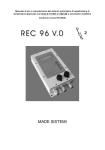
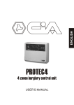
1.2 - General view of appliance
H
REC96-20083E (pict.1) includes :
C
A Electronic card containing the feeder part, the
CPU, memories and the analogue part of the
sensors
B The management firmware of the REC9620083E
C Back-lit LCD alphanumeric display
D Card 3 keys + no. 2 led
E Container IP 65
F Power supply and input and output connections
G Connector for PC
H Printer report
I Guarantee marks (inside)
G
D
E
I
F
pict. 1
Installation
This chapter provides information regarding correct positioning of the equipment and its electrical
connection to other connected or compatible devices.
2.1 - Central positioning
All the following operations of installation of REC96-2008E must be done by technical
assistance personnel.
REC96-2008E has been developed to be applied outside of refrigerated cells of trucks.
Before starting the installation check that the device is in working order by doing at least one
temperature reading test and a printout of the stored data and lastly check for the warranty
seal (pict.1).
The first operation is to fix the support to the vehicle
dashboard in the proper place, bending the upper, lower and
lateral internal tabs towards the outside of the support. .
At this point detach the panel from the body of the
instrument. After to have connected supply and sensors,
insert the body into the support and fix using two lateral
screws.
Complete the installation by reattaching the panel to the
body of the instrument
6
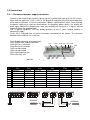
2.2 Connections
2.2.1 - Sensors and power supply connection
Correct system feed will be shown by lighting up of the yellow back lighting of the LCD screen.
Each time the appliance is fed, it starts a self-diagnostic sequence to check correct operation
of the internal elements. In case of malfunction it blocks, signalling fault status. Once installed,
the power supply must never be disconnected. As temporary power returns, the display will
once again indicate the temperatures read and recording will continue in a regular manner
without to loose the recorded data.
N.B: In optimal conditions, the Ram battery provides at least 2 years’ holding capacity in
absence of supply.
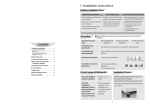
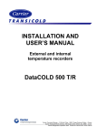
In fig. 2/B is indicated how to realize the power connection to the device. The minimum
diameter of the cable to use is 0.5 mm.
CN1= Supply connector and output/input
CN2= GPRS-GPS module connector
CN3= Sensor 1 connector
CN4= Sensor 2 connector
CN5= not connected
CN6= not connected
SG1= Antitampering seal
SG2= Warranty seal
CN1
CN2
CN6 CN3 CN4 CN5
SG1
SG2
(pict 2/b)
n°
1
2
3
4
5
6
7
8
9
CN1
Negative
Positive
Out (+)
Alarm 1
Alarm 2
Input 1 (+)
Input 1 (-)
Input 2 (+)
Input 2 (-)
CN2
Positive
Negative
CTS
RX
TX
RTS
CN3
Resistor
Common
Common
CN4
Resistor
Common
Common
SON96V.0
CN5
Resistor
Common
Common
CN6
Not conn.
Not conn.
Not conn.
SON96V.0
7
The sensors must never be disconnected from the temperature recorder. If that happens the
written SNC will be visualized. The reset procedure must be carefully followed keeping in mind
the regulations for measurement equipment.
If the temperature read exceeds the measurement limits +/- OUT will be displayed. With the
same text the events will be stored in memory.
Sensor technical characteristics are given in the chapter "Connected or compatible equipment
and devices".
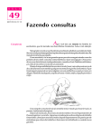
It’s advised to insert a fusible along the supply cable like show in picture 3.
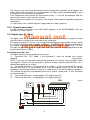
2.2.2 - Repeater connection
In order to obtain connection of the LED 00/01 repeaters to the REC96-20083E, carry out
connection as show in pict. 3.
2.2.3 Digital input D1 “Porta”
Manual not
reproducible
The digital input D1 is reserved for record and control of the state of a magnetic contact
(normally close) installed on the main door of the refrigerator.
Brief opening (major of 1.5 msec.) are not left out but temporarily accumulated and then stored
as a single event at the end of logging in progress. The port status is obviously displayed on
the display or printed on the documents produced with a special symbol and / or text.
The door can generate an acoustic/light alarm and send a text message if programmed to do.
Illustrated connection to Fig. 3
2.2.4 Digital input D2 “Aux”
The digital input D2 can be configured in four ways:
1)
Command "ON / OFF fridge": If the command is used, the recorder must remain
powered
permanently.
NOTE: If you are not connected automatically ignored the first power of the recorder. Follow
the diagram in Figure 3. for the connections. Refer to chapter "Autostart and ExtraTime" for a
detailed description of the service
2)
Command "defroster": The presence of a voltage > 8 Vdc on command D2 (input2)
indicates that there is an active defrost cycle. Even short defrost cycles are not left out but
temporarily accumulated and then stored as a single event at the end of logging in progress.
The viewing and printing are produced event with a special symbol and / or text. Illustrated
connection to pict. 3
3)
Command "side door": see paragraph 2.2.3 (digital input D1)
4)
Command "Services": see paragraph 2.2.4 (digital input D2)
CN1
Fault
Alarm
Repeater Repeater
+Refrigerator
Fusible 3A
(
)
ON/OFF
command switch
Door switch
(normally close)
+
-
8
pict.3
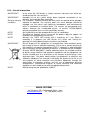
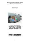
2.3 – Sensor Installation
Installation method for the sensor of the temperature recorder REC96-20083E following the
regulation D.M. 493 of 25/09/95 (repealed)
Refrigerator cell with bulkhead
Sensor2= F ront
=
Bulkhead
Sensor1= Rear
=
=
=
Refrigerating unit
Length of refrigerator cell less than 10 m.
Sensor1= Rear
=
Refrigerating unit
=
Length of refrigerator cell more than 10 m.
1 m.
2.5 m.
Sensor2= Front
Sensor1= Rear
=
Refrigerating unit
=
General precautions on sensor installation:
•
•
•
Do not place sensors in direct contact with walls.
Avoid objects being placed between the air outlet of the evaporator and the sensor.
Position the sensor’s most sensitive side (metallic side) toward the refrigerating unit.
9
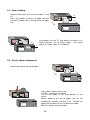
2.4 – Paper loading
Remove front panel and insert the paper in slot
"A".
Press the3button to make the paper advance
until there is about 10 cm. coming out of the upper
slot..
"A"
MADE
SISTEMI
MADE
SISTEMI
"C"
Insert paper into slot "C" and replace the panel in its
original position. Cut off excess paper. (for further
details on "Paper feed" see Chapter 6)
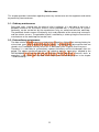
2.5 – Printer ribbon replacement
Remove front panel and roll of paper.
MADE
SISTEMI
MADE
SISTEMI
Press where shown by the arrow.
("PUSH" is written on the ribbon)
Put the new ribbon in the same position as the
former.
Before replacing the roll of paper, turn on the
temperature recorder and press the 3button for
paper feed for about 10 sec. to tighten the ribbon.
After this replace the roll of paper.
10
Maintenance
This chapter provides information regarding necessary maintenance on the equipment and advice
on preventing inconveniences.
3.1 - Ordinary maintenance
Every two years, starting from the date of initial installation, it is advisable to carry out a
periodical check of the instrument and the sensor provided with it. Assessment of system
conformity can be carried out by the manufacturer or by an authorised technical workshop.
The periodical checks concern functionality tests and calibration of the measuring instrument
and the relative sensors. The periodical check is certified by a sticker giving the name of the
manufacturer or the workshop that carried it out.
3.2 - Extraordinary maintenance
Manual not
reproducible
The data relative to measurements carried out are stored in a lithium Ram memory battery for
at least two years also in absence of external supply. The configuration data and the clock are
stored in the Timekeeper memory which has its own battery with a typical life of five years.
Therefore, it is advisable to systematically replace the battery and the timekeeper after this
period. The above mentioned operations for replacing parts or accessories coupled to the
REC96-20083E must be carried out by technical service personnel. Eventual faults or
anomalies in the system are signalled on the display with the wordings given in the chapter
"Troubleshooting".
11
FUNCTIONS
User menu
This chapter deals with the various functions available to the user for using the REC96-20083E.
Some instrument pre-adjustment parameters can only be modified by the maker. In order to
modify these parameters the container MUST be opened, removing the guarantee seals. The
instrument pre-adjustment parameters which don’t modify the metric part can be changed through
the appropriate software.
Customer access: The user menu is accessed by keeping the key pressed for a few seconds,
after which the following wording appears “Print Data”. Subsequently to push the key 3or4to
catch the desired menu and to push to select it.
In the main menu, if no key is pressed, the system will be automatically restarted after 8 sec. while
in the user menu the restart time is 30 sec.
In case of programming error it is not possible to restore previous parameters or maker
parameters.
4.2 - Print stored data (PRINT DATA)
Menu to print the mission data. The printout request resolution is daily.
To enter in this section to execute the procedure “Customer access”.
3or4and push the key . To repeat the operation
to set finish day. Subsequently the keys 3or4will be used to reproduce a printout in text or
To select the start day through the keys
graphic mode and with real or average data (moving average 3° type). A final selection
"Sector", allows you to print only the desired channels.
N.B.: In all the cases it does not identify a choice, will be considered pre-adjusted mode.
N.B: In graphic mode the first day printed will be the most recent.
N.B.: Push for 2 sec. the key
to stop the printout.
4.2 - Alarm regulation (ALARM SET)
To enter in this section to execute the procedure “Customer access”.
It allow to enable or disable the system’s internal ringer ("Acoustic ") and to configure the
delay activation alarm ("Activ.Delay") between 0 and 60 min. and the intervention of the initial
delay enabling alarms set at 30 min. It allows the pre-adjustment (in bands) or manual
regulation of the Min and Max threshold of the alarm thermostat for single channel ( "C1
(Rear) ", "C2 (Front) " ) or simultaneously (Monocompart).
The reactivating of acoustic alarm is automatic at every exit of regulation and/or thermostat
enable menu.
92/1/CEE Configuration
In agreement by the norm 91/1/CEE the thermostat regulations are limited.
With "Manual Reg", The thermostat are adjustable in the interval between -15°C e -59°C
or pre-adjusted in bands " Frozed" (max. -15°C min -35°C)
NB: The thermostats are not excludibles. (exclusion menu disabled).
12
Open Configuration
With "Manual Reg.", the thermostats are adjustable in the interval between +59°C e -59°C
or pre-adjusted in bands:
Bands
Frozen
Refrigerated
Chilled
Aired
Temp. max
-15 °C
-7 °C
+4 °C
+35 °C
Temp. min
-35 °C
-10 °C
-1 °C
0 °C
NOTE: The thermostats are excludable.
NOTE: In the case that the internal ringer is enabled it will be possible to turn it off by pressing
one of the 3 keys on the front panel. This operation will not turn off the repeater remote. By
using the appropriate software (available from dealers) you can not activate the alarm system
failure on this alarm.
The internal and remote turned off is cancelled every time will exit from a menu or the system
will be restarted. There is an automatic internal turned off alarm after a time-out of 5 minutes.
The ringer is always enabled for fault alarm.
4.3 - Display stored data (VIEW DATA)
This only displays the stored data and the last 8 fault events, if present, on the screen.
Search resolution is daily for the data stored in "(+) Historic".
To enter in this section to execute the procedure "Customer access". With the presence of at
least one anomaly it is enabled the option "(-) Fault".
Approaching to the "Fault" archives is possible to reset the yellow led "FLT" only if the anomaly
is not running. "Enn Res (+)". (Enn = alarm code, see fault table).
To select the desired day through the keys 3or4and then push the key .
To start the consultation press on the keys
3or4.
The stored data will be displayed in
relation to the recording interval chosen. If the key 3or4is held pressed for more then one
second, will begin an automatic scroll of the stored data with an continuous increase advance
speed.
When the display data vision is finished to press the key to exit from the menu.
Note: The fault menu is showed and enabled only if one anomaly is happened. In this case is
activate the memory reset option that power off the yellow blinking led and to send the event in
a circular code of max 8 faults with own hour-date, progressive number and alarm code. The
fault logger can be deleted only from authorized dealer. With repeated events of different kind,
all are stored but only the last is displayed to reset.
4.4 - Definition of personal code (PERSONAL ID.)
When accessing this menu to enter another identification code (e.g. vehicle number plate or
owner’s name) with a maximum of 12 characters.
The personal code is evidenced in each printout, data download or SMS service.
To enter in this section to execute the procedure "Customer access".
3or4allows to search the desired character, while the key is used to accept
the made choice. After insertion of twelfth character press "(Save) (+) (4)".
The keys
13
4.5 - Regulation LCD (LCD ADJUST.)
To enter in this section to execute the procedure "Customer access".
It allows the regulation of "brightness" of the display’s back-lit in 15 levels and of the "Contrast"
in 15 steps between + 30° e -30° of corner viewing.
N.B: Attention! At extreme temperature can be necessary the contrast regulation for a better
visibility of the display.
A third option "TimerLed" allows the exclusion of the autopower-off back-lit, timer therefore to
remain always ON.
NB: If the TimerLed is enabled the back-lit is ignited by pressing whichever key and it will be
turned off automatically after 30 sec. from the last key pressing.
4.6 - Direct print configuration (DEF.PRINT.K)
To enter in this section to execute the procedure "Customer access".
List of commands which allow to execute a printout by pressing only the key 4(Print). There
are 4 different kind of direct printout.
• Print mission: In the "mission" mode the data stored from the marker “beginning of
mission” to now are printed. This marker is set by a print operation.
• Print last period: In the "Last period" mode all data stored in a period from 3 hours to 21
days is printed. The value is adjustable from the keyboard.
• Print from last ON: In the "Last On" mode all data stored since the last time the
instrument or the refrigeration unit was turned to now are printed..
• Print Delivery ticket: In the "Delivery" mode the temperature at the time of request is
printed. Alternatively it is possible to request a "log print" in which the last 62 deliveries are
indicated.
The configuration is completed with the choice of the data presentation "MODE" that can be
"REAL" (showed the real measured data) or "AVERAGE" (showed the moving average 3°type
data) and from the printout "STYLE" in "Text " or "Graphic" format. A final selection "Sector",
allows you to print only the desired channels. The available choices will be in relation to the
compatible menu with previous selection.
4.7 - Language selection (SET LANGUAGE)
To enter in this section to execute the procedure "Customer access".
The choice can be made between 5 language: "Italiano", "English", Française", Deutsch",
"Espanol".
All the texts show on the display, printout or SMS will be translated in the language chosen
with the exception of the 12 characters used as Personal Code.
4.8 – SMS Service
This menu is visible only if GSM service has been activated with the specific software. This
allows SMS messages to be sent through the net (if connected to the optional GSM device).
Please read the specific user manual for further details.
14
GSM
Management of a GSM device to send SMS messages for alarm signals and/or data storage.
Characteristics of GSM service:
1. Outgoing telephone numbers (to send SMS): 3 (programmable from PC)
2. PIN code: programmable with a PC
3. Send SMS for thermostat alarm: to be activated with a PC
4. Send SMS for registration each scan time: to be activated with a PC
5. Send SMS for machine failure REC96-20083E
6. Management of pending SMS (until new event) and line check for GSM presence, every 30
sec.
7. CALL CENTER service to download data and/or service configuration
Paper feed
Manual not
reproducible
By pressing the3(Feed) button for about 2 seconds the paper feeds for as long as the button is
pressed.
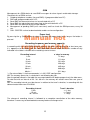
Recording frequency and memory capacity
In according with the norm EN12830 which imposes the data’s conservation for at least one year,
it is opportune to remember that the data download must be made within the number of day
indicated in the table in relation to the recording interval chosen.
Recording interval
n° days in memory
1 min
21 days
5 min
111 days
10 min
221 days
15 min
329 days
20 min
435 days
30 min *
640 days
60 min *
1211 days
* = Do not available if the thermorecorder is in 92/1/CEE configuration.
NB: The memory dimension is calculated in not following day too.
After the period indicate in the table the new acquired data will delete progressively the older ones.
To note that with an interval of 20 - 30 - 60 min. the memory will contain more then one year of
data.
NB: The recording interval must be chosen in relation to the travel’s duration, in according with the
table extracted from norm EN12830
Recording interval
5 min
15 min
20 / 30 min
Travel’s duration
<= 1 day
<= 7 days
> 7 days
The change of recording interval is followed to a complete cancellation of the data memory,
therefore is necessary to download data memory before to change value.
15
Autostart and ExtraTime
The thermorecorder is equipped of a command called "AUTOSTART" used to optimise the data
memory when the device is always turned on and the alarm management during operative phases
or parking.
By connecting the command to the refrigeration unit it is possible to start the thermorecorder and
to enable the alarms at the same time of the unit power on.
When the refrigerator unit is 'ON' will be displayed the icon
near the vehicle icon,
instantaneously recording will restart and the thermostat alarms and the SMS service will be
enabled.
near the vehicle and it starts a
When the refrigerator unit is 'OFF' will be displayed the icon
countdown of 240 min. When it expires, if the refrigerator unit is OFF, the recording will be
stopped, the alarm thermostat and the SMS service disabled (if ACTIVE) showing the text “Stop
regist” on the display. In stop condition the direct print command is disabled, while the customer
menu is enabled.
To restart immediately the recording press the red key "4PRINT" for more than 2 seconds.
NB: All fault alarm are always enabled.
NB: AUTOSTART command is optional, and if not used will be automatically ignored at the first
thermorecorder power on. The command is re-enabled if is connected to a working unit for more
then one second.
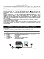
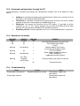
CONNECTED OR COMPATIBLE EQUIPMENT OR DEVICES
This chapter provides information regarding eventual equipment that can be connected to the
REC96-20083E.
All the following equipment must be installed by technical assistance personnel.
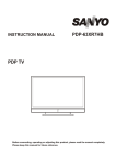
9.1
9.1
9.2
9.3
9.4
Name
SON96V.0 15mt
SON96V.0 11mt.
RIP96V.0
SAT02V.0
GSM01MD
LED00/01 V.0
POT01V.0
Description
3 wire sensor PT 100 dim. 6 x 50 - Sealed – Sensor Rear
3 wire sensor PT 100 dim. 6 x 50 - Sealed – Sensor Front
Remote repeater LCD display or PC
Satellite device
GSM device
Remote acoustic - optical repeaters.
Remote power repeaters.
5
6
1
2
4
3
pict. 7
16
N
1
2
3
4
5
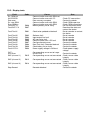
APPENDIX
This chapter (at point 10.1) gives a list of display icons and eventual faults that can occur on the
REC96-20083E, next to possible solutions to the relative problem. It also given instructions to be
followed for correct functioning and use.
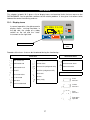
10.1 - Display icons
MADE
In normal operation, the alphanumeric
display shows running hour/date, in
the top side, the shape of a motor
vehicle on the left and the "state"
instrument on the right side.
SISTEMI
15 MAG 11:31
FLT.
+12.5
Feed
Print
Thermostat icon
ALR.
OPR.
Stop
Icons
area
Decodes of the icons that can be introduced during the functioning.:
Icons Area
Thermostat Icons
SMS service ON
Recorder paused
High thermostat alarm
GSM module ON
Remote alarm
Low thermostat alarm
GSM module fault
Autostart ON (refrigerator ON)
Thermostat active
Bell OFF
Call Centre Active
PC connected
Open door
ExtraTime (refrigerator OFF)
Truck Icon
Defrost ON
Services
Battery faulty
Thermostat blocked
Front
Sensor 1
Center
Sensor 2
Rear
Sensor 3
Door open
Input D2
17
10.2 – Advanced configurations through the PC
List of regulations available only through the configuration software (ask to the dealer for more
details)
•
•
•
•
Heading: It’s possible to heading each printout ticket. It allows the insertion of 12-16
characters in the head of the printout ticket.
Thermostat: It’s possible to select which type of alarm must be sent to the remote
repeater and if the its alarm output must be blinking or not.
Resolution: To increase the resolution of the LCD display, it’s possible to set the
resolution to 0.1 °C. This setting regards only the value visualized, while the data
memory will continue to be stored with the standard resolution.
Recording interval: Usually regulated to 15 min. can be modified from 1 to 60 min.
10.3 - Decodes of the alarms
LED OPR
(green)
off
off
LED FLT
(yellow)
off
on
LED ALR
(red)
=
=
blinking
fast blinking
=
blinking
on
=
blinking
slow blinking
=
blinking
=
on 2 Sec.
followed
with 3 beep
=
EVENTO
RECORDER BLOCKED OR NOT FED
RECORDER BLOCKED
FAULT
Memory battery flat or faulty
or fault on one or both sensors.
OUT OF ORDER
Power supply voltage insufficient
FAULT MEMORY
happened anomaly memory
=
Communication error with PC or printer
on
Thermostat alarm
10.4 - Troubleshooting
Fault
Display does not come on
Cause
Recorder blocked or not fed
Printer does not print
18
Cure
Check power supply and
connections
Check printer cable and
connections
10.5 - Display texts
Fault
Err. GSM net
232 ERROR
Data error
Err. rete GSM
Error GSM.nn
Fault BAT FL
Fault BAT. FA
Code
Fault Tec.01
E001
Clock to be updated or blocked!
Fault Tec.02
Fault Tec.04
Fault Tec.05
Fault Tec.06
Fault Tec.07
Fault Tec.08
Fault Tec.99
Fault VCC.LL
E002
E004
E005
E006
E007
E008
E099
E098
Software fault
Input-output line fault
A/D converter fault
Communication with LCD fault
Configuration data error
Ram Data fault. Recorder blocked
Clock battery flat or faulty
Power supply voltage insufficient
OUT
Print Error
SNC (channel 1)
E015
Corresponding sensor out of range
Printer Fault
Corresponding sensor not connected
SNC (channel 2)
E012
Corresponding sensor not connected
SNC (channel 3)
E018
Corresponding sensor not connected
Stop Record
E096
E097
Cause
Communication error with GSM net
Communication error with PC
Data memory corrupted
Communication error with GSM
Communication error with GSM
Memory battery flat or faulty
Recorder blocked
19
Cure
Check PC connections
Contact the dealer
Check GSM coperture
Check GSM connections
Do not disconnect feed!
Download the data and
contact the dealer
Reset recorder or contact
the dealer
Reset recorder
Reset recorder
Reset recorder
Reset recorder
Contact the dealer
Contact the dealer
Contact the dealer
Check power supply
voltage
Contact the dealer
Check sensor cable
integrity
Check sensor cable
integrity
Check sensor cable
integrity
Contact the dealer
10.6 – Useful information
IMPORTANT !
In the event the LCD breaks a slightly corrosive substance can come out.
Avoid contact with skin and eyes
IMPORTANT !
Improper use of the system brings about complete cancellation of the
warranty and unreliable data acquisition.
General warranty For 18 months. Products found to be faulty within this period will be promptly
conditions
replaced or repaired. The warranty does non cover damage caused by
improper use, but covers early ageing or breakdowns and manufacturing
faults in mechanical or electrical parts. The sensors are guaranteed for 6
months, whereas the incorporated printer, 12 months. REC96-20083E
without guaranteed seals are non covered by warranty.
NOTE
No responsibility con be accepted for the loss of stored data.
NOTE
Resetting the recorder means turning off the power supply for approx. 10
seconds and subsequently turning it on.
NOTE
Normally the "OPR" LED flashes with a frequency of 1 sec. When a
recording is in progress the LED flashes at a faster rate. During this
operation all the keyboard and print functions are disabled.
IMPORTANT !
Do not dispose of this equipment as miscellaneous solid municipal waste,
but arrange to have it collected separately. The re-use or correct recycling of
the electronic and electrical equipment (EEE) is important in order to protect
the environment and the well-being of humans. In accordance with European
Directive WEEE 2002/96/EC, special collection points are available to which
to deliver waste electrical and electronic equipment and the equipment can
also be handed over to a distributor at the moment of purchasing a new
equivalent type. The public administration and producers of electrical and
electronic equipment are involved in facilitating the processes of the re-use
and recovery of waste electrical and electronic equipment through the
organisation of collection activities and the use of appropriate planning
arrangements. Unauthorised disposal of waste electrical and electronic
equipment is punishable by law with the appropriate penalties.
NOTE
Manual being revised: updated to 18/05/12
________________________________________________
M ADE SISTEMI
via Berlinguer, 59 - Forlimpopoli (Forlì) - Italy
www.madesistemi.it - Tel. +39 (0543) 743127
20