1
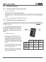
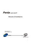
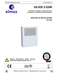
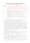
ITALIANO
ENGLISH
PROTEC4
4 zones burglary central unit
USER’S MANUAL
PROTEC4 - User’s manual
Index
Chapter 1
Introduction
19
1.1 Central unit description ...................................................................................................19
1.2 Operating features ..........................................................................................................19
1.3 Technical features...........................................................................................................20
Chapter 2
Installation
21
2.1 General instructions........................................................................................................21
2.2 Power supply ..................................................................................................................21
2.3 Connections....................................................................................................................22
2.3.1 Electronic key.....................................................................................................23
2.3.2 Reed contacts and volumetric detectors ............................................................24
2.3.3 Telephone dialer.................................................................................................25
2.3.4 Sirens.................................................................................................................26
Chapter 3
Programming
27
3.1 Exiting time regulation ....................................................................................................27
3.2 Entering time regulation..................................................................................................27
3.3 Alarm time regulation......................................................................................................27
Chapter 4
Operating
28
4.1 Panel description ............................................................................................................28
4.2 System enabling .............................................................................................................29
4.2.1 Enabling by the front panel key..........................................................................29
4.2.2 Enabling by other command system..................................................................29
4.3 System disabling.............................................................................................................30
4.3.1 Disabling by the front panel key .........................................................................30
4.3.2 Disabling by other command system .................................................................30
4.4 Zones exclusion..............................................................................................................30
4.5 Zones operating..............................................................................................................31
4.5.1 Zone 1 (immediated)..........................................................................................31
4.5.2 Zone 2 (immediated)..........................................................................................31
4.5.3 Zone 3 (delayed)................................................................................................31
4.5.4 Zone 24h (immediated)......................................................................................31
4.6 Alarm memory ................................................................................................................31
Chapter 5
Maintenance
32
5.1 Components to change...................................................................................................32
5.2 Cleaning..........................................................................................................................32
5.3 Fuses ...........................................................................................................................32
18
Introduction
1
Introduction
Dear customer,
we desire thank you for buying a CIA product. We recommend us to read this manual with
attention, because it will be very useful in phase of installation and use.
As CIA customer you can make use of a series of services, such as the technical telephone
assistance on the CIA products.
1.1
Central unit description
The PROTEC4 is a burglary central unit with microprocessor technology to use on the
whole of a burglary protection system for habitation and commercial rooms of small and middle
dimensions.
It is to be used with the perimetral protection magnetic sensors, and/or with the volumetric
detectors.
The alarm can be:sounding/luminous,with the autopowered SA310 siren for outdoor use;
sounding, with the piezoelectric SP31 siren for inside use; telephonic, with the TD81 telephone
dialer.
1.2
!
!
!
!
!
!
!
!
!
!
!
!
!
Operating features
4 protection zones: (1 delayed, 2 immediate, 1 24 hours) with alarm memory.
All zones singly excludibles.
Exit timing adjustable from 5 up to 75 sec.
Entrance time from 5 up to 90 sec.
Alarm duration from 30 up to 600 sec.
Control LEDs: main voltage presence, exit timing and zone status.
Visualization of the zones state with central unit switched off.
Protection fuse on sirens voltage output and service voltage output.
Sabotage alarm for attempt to exclude zone when the central is switched on.
Output for connection for controller systems SK,KB and SCM (electronic key, electronic
keyboard and magnetic card).
"ALARM MEMORY" function for visualization of the zones that caused the alarm.
Central unit protection by intermal tamper (can be excluded for maintenance).
According to the 1° level of CEI 79-2 standard.
19
PROTEC4 - User’s manual
1.3
!
!
!
!
!
!
!
!
!
!
!
!
!
!
!
!
!
Technical features
Operating voltage:
Maximum current absorption:
Service output voltage:
Maximum current supplied on services output:
Fuse on services output voltage
Maximum current supplied on sirens output
Sirens output fuse:
Maximum current supplied by power supplier AL5:
Min operating temperature:
Max operating temperature:
Box protection level:
Buffer battery:
Fuse on primary of the power supply:
Fuse on secondary of the power supply:
Central unit dimensions:
Insulation class:
Prestation level:
HiLTRON
230V~ ±10% 50Hz
140mA
13V! ±5%
650mA
F type 1A
3A (connected to the battery)
Tipo F 3,15A
1A
5±2°C
40±2°C (relative humidity. 93±2%)
IP30
12V7Ah
F type 250mA
F type 1A
280x230x95mm
1°
®
S.r.l.
PROGETTAZIONE E PRODUZIONE APPARECCHIATURE ELETTRONICHE
DECLARATION OF
CONFORMITY
CONSTRUCTOR: HiLTRON S.r.l.
ADDRESS: Circ. Est. di Napoli compls. Lemar 80026 Casoria (NA)
TRADE MARK:
PRODUCT CODE: PROTEC4
PRODUCT DESCRIPTION: 4 ZONES BURGLARY CENTRAL UNIT
THE PRODUCT RESULTS CONFORM TO THE FOLLOWING STANDARDS REQUIREMENTS:
STND SPECIFICATION
TITLE
EN50081-1
EMISSION STND
Part.1: residential, commercial and light industry
EN50082-1
IMMUNITY STND
Part.1: residential, commercial and light industry
EN60335-1
SAFETY OF HOUSEHOLD AND SIMILAR ELECTRICAL
APPLIANCES
CONFORMITY WAS BASED ON EMC PERFORMANCE TESTS CONDUCTED ON SAMPLE RUNNING IN THE
DESIGNED WORKING CONDITIONS AS FOR ITS FUNCTIONAL PROJECT, IT MEETS 89/336/EEC AND 73/23
EEC REQUIREMENTS.
DATE
21 May 1999
20
COMPANY MANAGEMENT
Installation
2
Installation
2.1
General instructions
Do not install the device at places exposed to the bad weather or to the extreme
temperatures.
The central unit is protected from the opening, but the installation in a safe place is a
greater protection of the device.
For a strong and safe fixing, it needs making sure the wall surface is plane.
Fixing the device by the four fishers included in the central unit and no replacing them with
others of more small size.
Fixing the central unit at a height that allows an easy access to the frontal panel.
The central unit must be connected with an alarm system according to CEI 79-3 Standard
or similar.
!
!
!
!
!
!
2.2
Power supply
It ‘s important to know that the entire system is powered exclusively by the 12V 7,5Ah lead
battery inside of the burglary central unit; the lead battery is constantly in charge by the AL5
power supplier/battery connected to the 230V~ main power supply.
WARNING!
The main power supply 230Vac has to be connected to the power supplier/battery
charger AL5 by two 1,5mm² double-isolation wires coming from a sectioning switch(i.e.
a magneto-thermic protection switch) used exclusively for the burglary central unit.
Inside of the central unit positioning orderly the two wires, locking them by wrappers.
Switch
230V~
50Hz
main power supply
21
PROTEC4 - User’s manual
When the installation is finished, it needs to connect the red/black conductors equipped
with faston coming from the AL5 power supplier to the battery. Be careful about connection
polarity (Red=positive [+] of the battery; Black=negative [-] of the battery), so that no cause
great damages to the connected devices.
ATTENTION!
The 12V7Ah battery must always be connected. Ensure of its efficient charge state,
measuring the tension by a volt-meter, after disconnecting the main power supply from
the AL5 power supplier/battery charger by the sectioning switch. Also in case of
changing of the lead battery it’s necessary to disconnect the main power supply from
the AL5 power supplier/battery charger, to avoid that the entire system burden on it.
Don’t connect on 13Vcc services power supply output of the central unit (clamps [5] and
[6] "+12V") a load beyond 650mA.
After connecting the central unit and the siren batteries, it’s possible to power on the
system by the sectioning switch connected on the AL5. The “RETE” LED signals the effective
presence of the main voltage.
The PROTEC4 and the AL5 don’t need the ground connection, but for safety reasons and
for the respect of the laws in vigor we suggest to make and test a ground connection for the all
devices that need it.
2.3
Connections
1
1-2
3-4
5-6
7-8
8-9
10 - 11
12 - 13
12 - 14
12 - 15
12 - 16
*
22
2
3
4
5
6
7
8
9 10 11 12 13 14 15 16
Output in series to the key switch of the front panel. Cut to connect PX, SK or KB
command systems.
13Vcc output tension on system enabled for the telephone dialer enabling.
13Vcc regular output tension for volumetric detectors, telephone dialer, etc.
ATTENTION! Maximun current supplied: 650mA
13Vcc output tension to recharge the autopowered siren. In alarm condition this
tension falls.
13Vcc output tension in alarm condition for supplementary indoor sirens and
telephone dialer activation.
13Vcc output tension to command the LED on PX, SK or KB command systems.
(10) = red LED
(11) = green LED
24h anti-sabotage protection zone NC* line (immediated).
Zone 1 NC* line (immediated).
Zone 2 NC* line (immediated).
Zone 3 NC* line (delayed).
If the alarm zones are not used, the clamps must be arched.
Installation
2.3.1
Electronic key
Remove
the arch
In series to
the 24h line
ATTENTION!
Optional
connection*
SK100
SKI
A
B
C
D
* This connection will activate the 24h anti-sabotage protection alarm when a false key is
inserted in the SKI connector.
23
PROTEC4 - User’s manual
2.3.2
Reed contacts and volumetric detectors
In series to
the 24h line
Long wires
4S
Short wires
C451
2B4
Short wires
C401/P
4S
Long wires
PG12
ATTENTION!
The PROTEC4 doesn’t allow the connection of the ‘switch’ contacts for rolling
shutters type C778 directly on the terminal boards becouse this central unit hasn’t got
an impulse counter.
Use the SCHSW impulse counter board to connect the ‘switch’ contact for rolling shutters
type C778, or use the ‘switch’ contact for rolling shutters C800 with integrated impulse counter
for the direct connection to this central unit.
24
Installation
2.3.3
Telephone dialer
In series to
the 24h line
TD81
2B4
Phone
line
25
PROTEC4 - User’s manual
2.3.4
Sirens
In series to
the 24h line
SA310
2B2
SP31
2B2
26
Programmation
3
Programmation
3.1
Exiting time regulation
The exiting time allows the system user to leave the protected zones after the system
enabling. During this time a possible activation of the sensors of the all protection zones
doesn’t activate alarms.
This timing is adjustable from 5 to 75 seconds by the trimmer situated inside of the central
unit (see picture below).
The exiting time is signalled by the flashing of the green LED “USCITA” situated on the
front panel of the central unit.
3.2
Entering time regulation
The entering time allows the system user to access the protected environments and reach
the central unit to disable the system. During this time, a possible activation of the sensors
installed on the zone 1 doesn’t activate an alarm cycle.
This timing is adjustable from 5 to 90 seconds by the trimmer situated inside of the central
unit (see picture below).
If an electronic key or any command system is installed externally to the protected
environments it’s advisable to adjust to minimum this timing.
3.3
Alarm time regulation
The alarm time duration is adjustable from 30 seconds to 10 minutes by the trimmer
situated inside of the central unit (see picture below).
Exiting time
Entering time
Alarm time
27
PROTEC4 - User’s manual
4
Operating
4.1
Front panel description
1
1
2
3
"RETE" red LED
on
off
3
blinking
8
9
12
11
10
6
24h zone status control LED
on
off
blinking
presence of main supply
absence of main supply
zona aperta
zona chiusa
zona autoesclusa
during the entering time
or in alarm condition
ALARM MEMORY
8
9
Zone1, zone 2, zone 3 status control LED
on
off
*blinking
zona aperta
zona chiusa
ALARM MEMORY
"USCITA" green LED
* with the
on
blinking
off
system disabled
during the exiting time
system enabled
"MEMORIA ALLARME" button
pressed
28
7
zone status
visualization
On system disabled, by pressing this button, the
blinking zones status control LEDs 7 , 8 e 9
indicate the ALARM MEMORY (i.e. the zone
that caused the alarm).
7
5
6
"ALLARME" yellow LED
on
4
5
released
Key switch
Allows to enable / disable the system. If there's
an electronic key or another command system ,
this switch has always to be turned on the
“INSERITO” position.
2
4
ALARM MEMORY
visualization
5
button pressed.
10 Zones exclusion/inclusion buttons
11
On system disabled, it is possible to exclude a
12 zone by pressing the relative button; the LED
upstanding the button starts blinking. The zone
protection willnot be included during the system
enabling.
Operating
4.2
System enabling
4.2.1
Enabling by the front panel key switch
!
Verify that the zone status LEDs 3 and 4 are turned off.
If they’re switched on it’s necessary to close the doors and windows relative to the zone
signalled opened. It’s also possible that the zone signalled opened could be the one
relative to the volumetric detectors; in this case the exiting time will allow to exit the
protected area without activating the alarm.
!
Turn the key switch
!
The green LED “USCITA”
protected areas.
!
When the exiting time is finished, the green LED "USCITA"
system is enabled.
4.2.2
1
in the “ON” position.
8
starts blinking indicating the exiting time, in which to leave the
8
turns off indicating that the
Enabling by other command system
If an electronic key system, a proximity key system, or an electronic keypad system is
installed outside of the protected areas, it's necessary to leave the key switch 1 ALWAYS in the
“ON” position.
All the SKI connector for the electronic
key, the PXR reader for the proximity key
and the KBC, KBM and KBT keypads have
two LEDs, one green and one red,
indicating the central unit status (see table
beside).
GREEN
LED
RED
LED
To enable the system:
!
Verify that the red LED is turned off.
If it's turned on, it's necessary to close
the opened doors or windows relative
to the zone that is signalled opened in
the central unit.
!
Insert the electronic key, or approach
the proximity key to the reader, or digit
the code on the keypad.
!
The green LED turns off indicating that
the system is enabled.
ON
FLASH
OFF
GREEN
LED
System
disabled
System
disabled
Excluded zone
System
enabled
RED
LED
Opened
zone/s
Alarm
memory
Closed
zones
BOTH
Exiting
time
29
PROTEC4 - User’s manual
4.3
System disabling
4.3.1
Disabling by the front panel key switch
!
Open the entering door.
!
The yellow LED “ALLARME” 3 starts blinking.
The alarm will not activates immediately becouse the entering door is usually protected by
the delayed zone 1: the entering time will allows to reach the central unit to disable the
system.
!
Turn the key switch
4.3.2
1
in the “DISINSERITO” position.
Disabling by other command system
If an electronic key system, a proximity key system, or an electronic keypad system is
installed outside of the protected areas, it's necessary to leave the key switch 1 ALWAYS in the
“INSERITO” position.
All the SKI connector for the electronic
key, the PXR reader for the proximity key
and the KBC, KBM and KBT keypads have
two LEDs, one green and one red,
indicating the central unit status (see table
beside).
GREEN
LED
RED
LED
To disable the system:
!
Verify that the red LED is turned off.
If it's blinking, it means that an alarm
was happened, precisely on the zone
signalled in the central unit with the
zone status LED blinking, after having
pressed the “MEMORIA ALLARME" 5
button.
!
Insert the electronic key, or approach
the proximity key to the reader, or digit
the code on the keypad.
!
The green LED turns on (or blinks, if
there's an excluded zone) indicating
that the system is disabled.
30
ON
FLASH
OFF
GREEN
LED
System
disabled
System
disabled
Excluded zone
System
enabled
RED
LED
Opened
zone/s
Alarm
memory
Closed
zones
BOTH
Exiting
time
Operating
4.4
Zones exclusion
From the front panel it is possible to exclude the zones 1, 2 and 3 simply by pressing the
zone related exclusion button. The exclusion of the zone is visualized by the flash of the zone
related LED.
4.5
Zones operating
The four protection zones have different operating characteristics.
4.5.1
!
!
!
On system enabled, the opening of the NC line immediately activates an alarm cycle.
The alarm is active for the alarm time setted (par. 3.3).
This zone is excludible from the front panel.
4.5.2
!
!
!
!
!
!
!
4.6
Zone 3 (delayed)
On system enabled, the opening of the NC line activates an alarm cycle after the entering
time setted (par. 3.2).
The alarm is active for the alarm time setted (par. 3.3).
This zone is excludible from the front panel.
4.5.4
!
Zone 2 (immediated)
On system enabled, the opening of the NC line immediately activates an alarm cycle.
The alarm is active for the alarm time setted (par. 3.3).
This zone is excludible from the front panel.
4.5.3
!
Zone 1 (immediated)
Zone 24h (immediated)
On system disabled, the opening of the NC circuit activates immediately an alarm cycle of
few seconds, then the zone autoexcludes till the line is opened.
On system enabled, the opening of the NC circuit activates immediately an alarm cycle.
The alarm cycle is active for the alarm time setted (par. 3.3).
Alarm memory
On system disabled, pressing the "MEMORIA ALLARME" key, the zone control LEDs
indicate the zone that caused the previous alarm.
31
PROTEC4 - User’s manual
5
Maintenance
5.1
Battery
It is advisable to check the battery connected to the AL5 power supplier/battery charger
and the battery inside of the self-powered sirens.
5.2
Cleaning
For the central unit cleaning, use only a soft and humid cloth.
No use absolutely diluents and abrasive sponges.
5.3
Fuses
F1 Sirens output
F2 Services output
32
F type 3A
F type 1A
299ADE-1.01