1
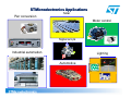
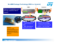
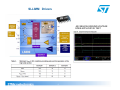
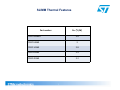
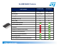
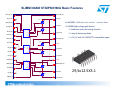
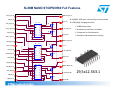
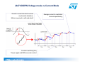
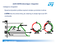
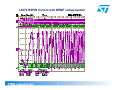
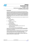
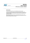
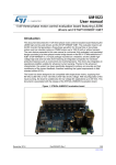
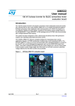
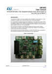
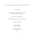
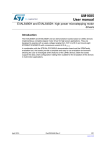
Analog & Power November 2011
Riccardo Tosoni(FAE STM)
STMicroelectronics Applications
Pwr conversion
Solar
Motor control
Signal acq &
Mems
Industrial automation
Lighting
Automotive
1
High Voltage motor control
Industrial & Power Conversion Division
Off Line Power Supply Business Unit
SLLIMM™ family
Small Low Loss Intelligent Molded Module
SLLIMM™ proposal for simple and compact solution for
motor drive up to 2kW
SLLIMM Package Technology (DBC vs. Ceramic)
Ceramic
DBC
Highest Integration Level
Driving powerful BLDC
motors
6 IGBT &
3 Drivers inside
with thermal management
Integrated Op-Amp and
Comparator for sensing &
protection
Au wire
I
C
Al wire
IGBT Diode
Ceramic
o DIP Molded Package
o PCB for drivers &
SMD
o DBC (Direct Bond
Copper) for power
stage (copper surface
exposed)
4
• DIP Molded Package
• PCB for drivers & SMD
• Lead frame and exposed
ceramic sink for power
stage
SLLIMM Drivers
-50V BELOW-GROUND VOLTAGE
SPIKE APPLICATIVE TEST
5
SLLIMM Road Map
STGIPS10K60A
STGIPS10K60T
STGIPS14K60T
STGIPS14K60
STGIPL14K60
STGIPS20K60
STGIPL20K60
25
25
25
25
38
25
38
Pkg Size [mm]
44.4*22.0*5.4
44.4*22.0*5.4
44.4*22.0*5.4
44.4*22.0*5.
4
49.6*24.5*5.4
44.4*22.0*5.
4
49.6*24.5*5.
4
DBC substrate
yes
yes
yes
yes
yes
yes
yes
Voltage
[V]
600
600
600
600
600
600
600
Current @
Tc=25°C
[A]
10
10
14
14
15
18
20
Rth (max) [ºC/W]
3.8
3.8
3
3
2.8
2.4
2.2
NTC
yes
yes
yes
no
yes
no
yes
Integrated
Bootstrap diode
yes
yes
yes
yes
yes
yes
yes
Smart shutdown
function
no
no
no
yes
yes
yes
yes
SD function
no
yes
yes
yes
yes
yes
yes
Op-amps for
Advanced current
sensing
no
no
no
no
yes
no
yes
Comparator for
fault protection
no
no
no
yes (1pin)
yes (3pin)
yes (1pin)
yes (3pin)
PART NUMBER
Pin Count
6
SLIMM Thermal Features
Part number
RTH (°C/W)
STGIPS10K60A
3.8
STGIPS14K60
3
STGIPL14K60
2.8
STGIPS20K60
2.4
STGIPL20K60
2.2
7
SLLIMM Motor Control Power
STGIPS20K60
STGIPL20K60
STGIPL14K60
STGIPS14K60
STGIPS14K60T
STGIPS10K60A
1kW STGIPS10K60T
2kW
1.5kW
8
Output Power
NEWS !!!
SLLIMM NANO Motor drive up to 100W
Benefits
High quality and Reliability
Advanced protection function
Tj = from -40ºC
to 150ºC
Improved efficiency
Reduce EMI and noise
Reduce total system cost
Easy Layout
Main features and integrated functions
Main Applications
● 600 V, 3 A ratings
● 3-phase IGBT inverter bridge including:
– 6 low-loss and short-circuit protected IGBTs
– 6 low forward voltage drop and soft recovery freewheeling
diodes
● Three control ICs for gate driving and protection including:
– smart shutdown function
– comparator for fault protection against overcurrent and shortcircuit
– op amp for advanced current sensing
– three integrated bootstrap diodes
– interlocking function
– undervoltage lockout
9
General purpose Low power motor drives
Dish washers
Compressor drives
Refrigerators
Pumps
Air Con
Fans
NEWS!!!!!!!!
2012
Samples available
SLLIMM NANO Features
STGIPN3H60A
STGIPN3H60
26
26
29,5x12.5X3.1
29,5x12.5X3.1
600
600
Current @ Tc=25°C [A]
3
3
RTH(J-A) [°C/W]
50
50
PART NUMBER
Pin Count
Pkg Size [mm]
Voltage [V]
Integrated bootstrap diode
Smart shutdown function
SD function
Op-amps for advanced current sensing
Comparator for fault protection
3.3/5V input interface compatibility
Interlocking function
Under Voltage Lock Out (on both Vcc and Vboot)
10
SLIMM NANO STGIPN3H60A Basic Features
LIN U (pin 16)
VBoot U (pin 17)
P (pin 18)
NC (pin 15)
T1
D1
6x 4A/600V IGBTs with ultra- soft fast recovery diode.
HIN U (pin 14)
U (pin 19)
VccU (pin 13)
LIN
NC (pin 12)
3x L6388 (High voltage gate driver)
T2
HIN
VCC
D2
VBOOT
N_U (pin 20)
OUT
LIN V (pin 11)
Dead time and interlocking function
HVG
LVG
GND
VBoot V (pin 21)
HIN V (pin 10)
Internal bootstrap diode
3.3V, 5V and 15V CMOS/TTL compatible inputs
T3
VccV (pin 9)
D3
LIN
NC (pin 8)
HIN
VCC
cut pin
VBOOT
HVG
N_V (pin 22)
OUT
T4
NC (pin 7)
LVG
GND
D4
N_V (pin 23)
NC (pin 6)
LIN W (pin 5)
cut pin
LIN
HIN W (pin 4)
HIN
VCC
VBOOT
HVG
T5
VBoot W (pin 24)
OUT
D16
VccW (pin 3)
NC (pin 2)
LVG
GND
W (pin 25)
T6
D18
GND (pin 1)
N_W (pin 26)
11
29,5x12.5X3.1
SLIMM NANO STGIPN3H60 Full Features
/LIN_U (pin 16)
VBOOT U (pin 17)
6x 4A/600V IGBTs with ultra-soft fast recovery diode.
/SD (pin 15)
3
VCC_U (pin 13)
4
5
CIN1 (pin 12)
6
7
8
/LIN_V (pin 11)
L6390
Vboot
SD/OD
HVG
HIN
OUT
VCC
NC
DT
NC
OP-
LVG
OPOUT
CP+
GND
OP+
16
15
T1
1
14
L6388 features plus:
U, VS_U (pin 19)
13
12
11
T21
10
D2
NU (pin 20)
9
5
6
7
8
OP2+ (pin 6)
SD/OD
HVG
HIN
OUT
VCC
NC
DT
NC
OP-
LVG
OPOUT
CP+
GND
OP+
16
15
T3
2
Vboot
14
Cut pin
D3
1
3
L6390
13
12
V, VS_V (pin 22)
T4
2
4
U2
LIN
11
D4
1
10
3
1
3
OPOUT2 (pin 7)
9
NV (pin 23)
Cut pin
/LIN_W (pin 5)
VCC_W (pin 3)
4
5
6
/SD (pin 2)
7
8
GND (pin 1)
HVG
HIN
OUT
VCC
NC
DT
NC
OP-
LVG
OPOUT
CP+
GND
OP+
16
15
T5
VBOOT_W (pin 24)
2
Vboot
SD/OD
14
D5
1
13
3
3
L6390
12
W, VS_W (pin 25)
11
10
9
T6
2
2
U3
LIN
D6
1
NW (pin 26)
3
1
HIN_W (pin 4)
OpAmp for advanced current sensing
VBOOT_V (pin 21)
2
OP2- (pin 8)
Shutdown pin and Smart shutdown
Comparator for fault detection
HIN_V (pin 10)
VCC_V (pin 9)
3x L6390 (High voltage gate driver)
D1
3
2
U1
LIN
2
1
3
HIN_U (pin 14)
2
P (pin 18)
12
29,5x12.5X3.1
Low power motor control board featuring
™
SLLIMM NANO STGIPN3H60
and MCU STM32F100C6T6
Industrial & Multi-Market Competence Center
& Power Transistor Division
STEVAL-IHM036V1 evaluation board
I&MMCC & PTD
Daniel Kohout
November 14, 2011
Target Applications
General purpose 3-phase inverter for 3-phase
permanent magnet synchronous motors with
vector field oriented control for output power up to
100W.
Inverter for high efficiency circulating water pump for heating
systems in single-family houses
High efficiency drain pump for home appliance white goods,
like dishwashers and washers
High efficiency and reliable solution for small power transfer
pumps for waste sludge – sewerage plants in singe-family
houses, waste piping
High efficiency transfer pumps for outlet condensation water
High efficiency exactor hoods and blowers for gas furnace
application
Compressor drives for fridges
Marketing positioning
STEVAL-IHM036V1 evaluation board:
The goal of the STEVAL-IHM036V1 demonstration board is to
present an design consisting in a 3-phase inverter bridge
based on 600V, 3A small loss intelligent molded module
STGIPN3H60 and STM32F100C6T6 MCU.
The SLLIMMTM NANO itself consist of short-circuit rugged
IGBT’s and wide range of auxiliary functions like under voltage
lockout and smart shut-down.
The system has been designed to for a field oriented control
(FOC).
System Architecture
User interface
2 x LED
Button
Potentiometer
MCU
Power supply
Block
Aux. power
Supply
VIPer16
EMI filter /
Rectifier /
Bulk cap.
cap.
Motor
SLLIMM™ NANO
STM32F100C6T6
Sensing (op. amp.)
Protection (comparator)
RS485 (Optional)
Sensing /
protection Block
Single shunt
resistor
Power
Block
Main Features
STEVAL-IHM036V1 main features:
Using IGBT SLLIMM™ NANO STGIPN3H60 in NDIP-26L molded
package
Maximum output power for applied motor up to 100 W
Single phase power supply: 195VAC to 265VAC, or direct DC line up to
+400VDC
Input in-rush current limiter controlled by NTC resistor
Based on STMicroelectronics's ARM™ Cortex-M3 core-based
STM32F100C6T6 microcontroller
Single shunt resistor current sensing method
Possibility to modify the board by adding RS-485 bus
EN55014 (CISPR 14), IEC 61000-4-5 and IEC61000-4-4 compliant
Compact and safe design
ST components used in the application
STEVAL-IHM036V1 bill of material includes:
1 x IGBT SLLIMM™ NANO STGIPN3H60
1 x MCU STM32F100C6T6 microcontroller
1 x PWM SMPS smart driver VIPer16LD
1 x Linear regulator L78L33CV
2 x High efficiency power rectifier STTH1L06U
2 x Small signal schottky diode BAT48JFILM
1 x Bus driver ST485EB (N.A.)
Why STGIPN3H60 SLLIMM™ NANO
Why STGIPN3H60:
600 V, 3A 3-phase IGBT inverter bridge including control ICs for gate driving and freewheeling
diodes
Internal bootstrap diode
Interlocking function
Optimized for low electromagnetic interference
VCESAT negative temperature coefficient
Short-circuit rugged IGBT
Under-voltage lockout
Fully isolated package
Smart shut down function
Op-amps for advanced current sensing
Comparators for fault protection against over temperature and over current
A good alternative to promote:
STGIPN3H60 A - The same IGBT‘s, no extra feature available (Op.Amp., comparator)
SLLIMMTM-nano for low power motor control up 100W
Main features:
Benefits:
• 600 V 3-phase IGBT inverter bridge including control ICs for
• Improved design time,
• Reduced manufacturing efforts,
• Increased reliability and quality level.
• Maximized efficiency, reduced EMI and noise
• Higher level of protection and lower propagation
gate driving and ultra - soft fast recovery freewheeling diodes
• Dead time and interlocking function
• Internal bootstrap diode
• 3.3V, 5V and 15V CMOS/TTL compatible inputs
• Smart shutdown function
• Integrated comparator for fault protection against over
current and short-circuit
• Integrated Op-amp for advanced current sensing
delay time.
• Small form factor (PCB space reduction)
Why VIPer16L
Why VIPer16L:
800 V avalanche rugged power section
Relative simple design
Operating frequency 60kHz
Hysteretic thermal shutdown
Limiting current with adjustable set point
A good alternative to promote:
VIPer06 - When less power is required
VIPer26 - When higher power is required (> 200 mA)
Why STM32F100C6T6
Why STM32F100C6T6 :
Low & medium-density value line, advanced ARM-based 32-bit MCU
LQFP48 7 × 7 mm package
Core: ARM 32-bit Cortex™-M3 CPU
2.0 to 3.6 V application supply and I/Os
32 Kbytes of Flash memory
Temperature range from -40 to 85˚C
A good alternative to promote:
STM32F100x8 or STM32F100xB, if larger Flash memory is requested
For Sales and Marketing
STEVAL-IHM036V1
Low power motor control board STEVAL-IHM036V1 featuring SLLIMM™
STGIPN3H60 and MCU STM32F100C6T6
Targeted to dishwasher, washer and dryer drain pumps, fridge
compressors, extractor hood fans and heating recirculation pumps
Single phase connection – input supply voltage from 195VAC to 265VAC
Possibility to use single supply or dual supply mode
For dual supply mode DC supply input from 18VDC to 400VDC
Complete motor control platform for output power up to 100W
Compliance with EN55014, IEC 61000-4-5 and IEC 61000-4-4
Over-temperature and over-current hardware protection
Possibility to modify the board with RS-485 interface
Single shunt current reading configuration
Ordering code: STEVAL-IHM036V1
User Manual: UM1483
On Stock by end of Q4/2011 (prototypes available now)
The STEVAL-IHM036V1 evaluation board
Technical Part
System Architecture
User interface
2 x LED
Button
Potentiometer
MCU
Power supply
Block
Aux. power
Supply
VIPer16
EMI filter /
Rectifier /
Bulk cap.
cap.
Motor
SLLIMM™ NANO
STM32F100C6T6
Sensing (op. amp.)
Protection (comparator)
RS485 (Optional)
Sensing /
protection Block
Single shunt
resistor
Power
Block
System Architecture
Control block:
Accept user commands, motor drive configuration parameters
provide appropriate digital signals to perform the proper motor driving strategy
Could be updated with driver ST485EB for RS485 BUS
Power block:
performs a power conversion from DC bus in to the motor
three-phase inverter topology
based on SLLIMM™ STGIPN3H60
Sensing / protection:
Single shunt topology
PMSM with using of FOC itself is conceived for sinusoidal shaped back-EMF
Fully using advantage of the SLLIMM™
Power supply block:
Single phase connecting - supply voltage 195VAC to 265VAC or direct DC line up to
+400VDC
System Architecture - Supply Block
Auxiliary power supply
(Bus voltage for inverter)
+325VDC
+15VDC
J5
INPUT
J1
(To IPM)
SW4
(To MCU, op. amp.)
NTC inrush limiter /
EMI filter /
Bridge rectifier /
Buck converter
Viper16
L78L33ACU
+3.3VDC
System Architecture - Supply Block
Includes rectifier bridge
In-rush current limiter – NTC resistor
Complete EMI filter based on CM choke, X2 and Y2 capacitors
EN55014, IEC61000-4-4 and IEC61000 4-5 compliant
Auxiliary power supply based on Viper16L in buck converter topology
Working frequency: 60 kHz
Single phase power supply: 195VAC to 265VAC or direct DC line up to
+400VDC
System Architecture - Power / Sensing Block
+325VDC BUS
SLLIMM™ NANO
COMPARATOR
Smart
SD
EM STOP
MCU
Motor
+
Phase A
-
Phase B
Vref
U
V
W
Phase C
STM32F100C6T6
Op. Amp.
+
-
R
Current
R
R
Sensing /
protection Block
R
R
+3.3V
R
Single shunt
Resistor 0.4R
R
Power Block
System Architecture - Power / Sensing Block
Based on SLLIMM™ STGIPN3H60
Designed for current up to 3A
Integrated drivers dice L6390
FOC with single shunt current reading for vector control method
Fully using integrated features of the SLLIMM™ :
Using integrated comparator for over-current protection
Direct connection to shut down function of the IPM
Advanced current sensing with integrated Op-Amp
Adjustable gain of operational amplifier with external resistor
network
System Architecture – Control block
JTAG interface
JTAG connector
MCU
STM32F100C6T6
USER interface
LED 1
LED 2
DAC 1
2 x LED
Button
Potentiometer
DAC 2
Button
Potentiometer
Hardware signals
RS485 (Optional)
IPM Temperature (NTC)
Over current / emergency STOP
Current
Bus voltage
PWM Channel U
PWM Channel V
PWM Channel W
System Architecture – Control block
Based on STM32F100C6T6
Generated PWM signals for SLLIMM™
User interface: LED, buttons, potentiometer, DAC
JTAG interface
Possibility to modify the board by adding RS485 serial interface
Sensing various signal with ADC channels
External 8 MHz crystal
+3.3V supply voltage
Control block – PMSM FOC library v3.0
The STM32 PMSM FOC Library v3.0 is a:
Motor Control Software Development Kit
To be used with STM32F103xx or STM32F100xx
For 3-phase Permanent Magnet Synchronous Motors
Library main features:
Single/Dual simultaneous vector control (FOC)
Sensor / Sensorless
Energy efficient, quiet, motor drive
Outstanding dynamic performances, speed range
Full customization through GUI
Wide range of hardware support, system configurations,
addressing applications from Home Appliances to Factory
Automation
Control block - ST Motor Control Workbench
(STMCWB)
ST Motor Control Workbench, in this version, is a PC code generator tool that
reduces the designer effort and time in the firmware development for all the ST
Motor control FW library (starting from STM32 PMSM FOC FW library 3.0). The
user through a graphical user interface (GUI) generate the parameter header files
which configures the library according the application needs.
Tools – Software part
Download:
STM32 FOC PMSM SDK v 3.0 firmware library zip file
http://www.st.com/internet/com/SOFTWARE_RESOURCES/SW_COMPONENT/FIRMWAR
E/stm32_pmsm_foc_motorcontrol_fwlib.zip
ST MC Workbench v 1.0.2 zip file
http://www.st.com/internet/com/SOFTWARE_RESOURCES/TOOL/CONFIGURATION_UTIL
ITY/motorcontrol_workbench.zip
Consult:
TN0516 “Overview of the STM32F103xx/STM32F100xx PMSM single/dual FOC SDK V3.0”
http://www.st.com/internet/com/TECHNICAL_RESOURCES/TECHNICAL_LITERATURE/TE
CHNICAL_NOTE/DM00026481.pdf
UM1052 “STM32F103 or STM32F100 PMSM single/dual FOC SDK V 3.0”
http://www.st.com/internet/com/TECHNICAL_RESOURCES/TECHNICAL_LITERATURE/US
ER_MANUAL/CD00298474.pdf
UM1053 “Advanced development Guide for STM32F103 or STM32F100 PMSM single/dual FOC
library”
http://www.st.com/internet/com/TECHNICAL_RESOURCES/TECHNICAL_LITERATURE/US
ER_MANUAL/CD00298482.pdf
STEVAL-IHM036V1 parameters - efficiency
Efficiency measurement:
Overall efficiency of the whole demonstration board is above
90% (test conditions- 230VAC, PWM 16kHz, Tamb 25˚C)
Consumption with no motor commutation (STNBY) ~0.6W
Efficiency
(%)
95.0
90.0
Efficiency n(%)
95˚C
81˚C
62˚C
85.0
113˚C
80.0
75.0
70.0
Temperature of the
STGIPN3H60
65.0
60.0
0
10
20
30
40
50
60
Electrical power (W)
70
80
90
100
STGIPN3H60 vs. Main Competitor FOC @ 16kHz
SINUSOIDAL FOC CONTROL – SINGLE SHUNT – 3200 RPM (160Hz) – 16kHz – STGIPN3H60
Electrical Pout
25W
50W (*)
75W (*)
95(*)
25°C
61°C
80°C
96°C
120°C
50°C
87°C
109°C
123°C @ 65W
-
75°C
116°C
122°C @ 35W
-
-
Ta
(*) or the maximum power according to a case temperature of 125°
125°C
SINUSOIDAL FOC CONTROL – SINGLE SHUNT – 3200 RPM (160Hz) – 16kHz – Main Competitor
Electrical Pout
25W
50W (*)
75W (*)
25°C
63°C
95°C
133°C @ 70W
50°C
93°C
126°C @ 47W
-
75°C
119°C
128°C @ 30W
-
Ta
(*) or the maximum power according to a case temperature of 125°
125°C
FOC 16kHz - TA = 50°C
FOC 16kHz - TA=25°C
130
128
Tc [°C]
Tc [°C]
STGIPN3H60 vs. Main Competitor FOC @ 16kHz
120
110
96
95
90
70
50
93
87
80
20
Main competitor
130
128
125
122
120
119
116
115
110
25
30
Electrical Power [W]
STGIPN3H60
25
30
35 40 45 50 55
Electrical Power [W]
STGIPN3H60
FOC 16kHz - TA = 75°C
Tc [°C]
109
90
STGIPN3H60
123
100
20 25 30 35 40 45 50 55 60 65 70 75 80 85 90 95 100
Electrical Power [W]
20
126
120
110
80
63
61
130
35
Main competitor
40
60
Main competitor
65
70
STEVAL-IHM036V1 parameters – compliance with
EN55014 (CISPR14-1)
The STEVAL-IHM036V1 evaluation board was tested to be
compliant with conducted radio disturbances according to CISPR14
specification, for frequency range from 150kHz to 30MHz
Frequency range 150kHz – 30MHz
Detector average; detector quasi peek
Measured on power supply lines (AC line: L and N)
STEVAL-IHM036V1 parameters – compliance with
IEC61000-4-4 and IEC61000-4-5
The board was tested to be compliant with IEC61000-4-4 burst
immunity:
Burst duration 15ms +/- 20% at 5kHz
Burst period 300ms +/- 20%
Polarity positive/negative
Applied to power supply lines (AC line: L and N)
Passed 2kV with criteria A (no damage, no influence)
The board was tested to be compliant with IEC61000-4-5 surge
immunity:
Polarity positive/negative
Duration time 10 events; repetition time 30s
Phase angle 0˚, 90˚, 180˚, 270˚ for each test condition
Common mode – applied among to AC line and PE earth
Differential mode – applied to AC line (L and N)
Passed 2kV line to line and 2kV line to earth
How to connect STEVAL-IHM036V1
JTAG
J-link, ST-link…
J3
J2
SHIMANO PMSM motor
J1
J5
+30VDC
Auxiliary +15V adapter
Supply source up to 30V, 3A capable
Schematic /1
INPUT PART WITH RECTIFIER
F1
2A
FUSE_SMALL
NTC1 10R-B57153S0100M
+Bus
C2
330nF/X2
VR1
592-275; p-600mW
C1
4.7nF/Y 2
C3
220nF/X2
D2
1N4007
R1
470k
C4
330nF/X2
1
IN_230VAC
+3.3V
C5
+
C6
4.7nF/Y 2
100uF/400V
D4
1N4007
2
3
2
1
T1
3
4
J1
D1
1N4007
D3
BAT48JFILM
R2
470k
D5
1N4007
Bus_v oltage
Div. ratio 116
C7
10nF
R3
8k2
CM_choke 12mH
+3.3V LINEAR
U2
L78L33ACU
U1 VIPe r1 6L D
Drain4
Drain3
Drain2
Drain1
COMP
4
3
2
1
+
Source4
Source3
Source2
Source1
C17
1uF/400V
VDD
LIM
FB
R7
68k
5
6
7
R5
120R
C8
100nF
R6
13k
C15
47nF
8
2
1
+15V AUX
C42
100nF
C9
100nF
+3.3V
C11
100nF
+
C10
47uF/6.3V
C12
100nF
+
C13
100nF
D6
STTH1L06A
C18
1uF/50V
L2
+15V
2.2mH
+15V
C20
D7
STTH1L06A
+3.3V
C16
220nF
+15V
J5
+15V
2
R4 51k
13
14
15
16
SHORTED
Vin
+15V
GND
470uH
3
L1
Vout
SW4
+Bus
1
BUCK CONVERTER
R8
7k5
+
D8
BZV55C18SMD
C19
100nF
100uF/25V
D9
LED 'green'
J2
1
2
3
MOTOR
phas e_W
phas e_V
phas e_U
C14
22uF/6.3V
Schematic /2
POWER INVERTER PART
U3
PWM-U-L
!SD
PWM-U-H
+15V
PWM-V-L
+
C24
4.7uF/25V
PWM-V-H
OP2-
C26
100nF
OU2
PWM-W-L
16
15
14
13
12
11
10
9
8
7
6
5
4
3
2
1
STGIPN3H60
VBOOT U
/LIN_U
/SD
HIN_U
VCC_U
CIN1
/LIN_V
HIN_V
VCC_V
OP2OPOUT2
OP2+
/LIN_W
HIN_W
VCC_W
/SD2
GND
P
U, VS_U
NU
VBOOT_V
V, VS_V
NV
VBOOT_W
W, VS_W
NW
17
C21
C22
1uF
1uF
+3.3V
R9
3k3
18
+Bus
19
phas e_U
!SD
EM_STOP
20
21
22
C27
330pF
C23
C25
1uF
1uF
25
C28
C29
26
1uF
1uF
phas e_V
23
24
+3.3V
RT1
NTC 10k
phas e_W
PWM-W-H
t
R10
1R6
+3.3V
R15 1k0
R14
n.c.
OU2
D10
R17
18k
+3.3V
R13
1R6
Het_temperature
C31
10nF
E_C
R18
4k7
C30
2.2nF
BAT48JFILM
+3.3V
R20 6k2
R19
6k2
OU2
C32
R22
1k
cinp
R21 1k
C33
33pF
TP1
T POINT 15V
TP5 T POINT CIN
+15V
TP2
T POINT 3.3V
TP3
T POINT GND
cinp
TP6 T POINT SD
+3.3V
R23 1k0
E_C
R12
1R6
R16 1k0
Current
100pF
R11
1R6
!SD
TP7 T POINT D_1
OP2-
DAC_1
TP4 T POINT C
TP8 T POINT D_2
Current
DAC_2
Schematic /3
MCU part
JTAG
LED_2
LED_1
+3.3V
+3.3V
PB4
PB3
PA15
PA14
R30
1M
C36
30pF
30pF
1
2
3
4
5
6
7
8
9
10
11
12
C37
100nF
L3
2.2uH
+
C39
4.7uF/6.3V
C40
100nF
+3.3V
VDD_3
VSS_3
PB9
PB8
BOOT0
PB7
PB6
PB5
PB4
PB3
PA15
PA14
Res
C38
U4
VBA
PC13
PC14
PC15
PD0
PD1
NRST
VSSA
VDDA
PA0
PA1
PA2
VDD_2
VSS_2
PA13
PA12
PA11
PA10
PA9
PA8
PB15
PB14
PB13
PB12
PA3
PA4
PA5
PA6
PA7
PB0
PB1
PB2
PB10
PB11
VSS_1
VDD_1
R31
10k
48
47
46
45
44
43
42
41
40
39
38
37
Y1 8MHz
PA13
PWM-W-H
PWM-V-H
PWM-U-H
PWM-W-L
PWM-V-L
PWM-U-L
!SD
PB4
PA15
PA13
PA14
R26
10k
PB3
Res
R28
10k
R29
10k
J3
13
14
15
16
17
18
19
20
21
22
23
24
STM32F100C6T6
36
35
34
33
32
31
30
29
28
27
26
25
+3.3V
1
2
3
4
5
6
7
8
9
10
11
12
13
14
15
16
17
18
19
20
+3.3V
+3.3V
R24
Pot
10k
+3.3V
Current
Bus_v oltage
DAC_1
DAC_2
SW
Het_temperature
Pot
+3.3V
R32
10k
R33
10k
R34
10k
R35
10k
R25
PB3
PB4
4k7
C34
PA13
PA14
SW
22nF
C35
SW1
+3.3V
+3.3V
R42
N.A.
R41
N.A.
U5 S T 485E B /N.A .
R40
N.A.
C41
N.A.
1
2
3
4
SW3
N.A.
RO
RE
DE
DI
Vcc
B
A
GND
8
7
6
5
J4
R38
N.A.
SW2
N.A.
1
2
3
RS-485/N.A.
R39
N.A.
68nF
LED_1
R36
1k6
LED_2
R37
1k6
User
R27
100R
D11
LED 'y ellow'
D12
LED 'y ellow'
Tools
Datasheets of available components:
STGIPN3H60 IPM
http://www.st.com/internet/com/TECHNICAL_R
ESOURCES/TECHNICAL_LITERATURE/DAT
ASHEET/DM00032611.pdf
VIPer16
http://www.st.com/internet/com/TECHNICAL_R
ESOURCES/TECHNICAL_LITERATURE/DAT
ASHEET/CD00218828.pdf
STM32F100C6T6
http://www.st.com/internet/com/TECHNICAL_R
ESOURCES/TECHNICAL_LITERATURE/DAT
ASHEET/CD00251732.pdf
User manual UM:1483
Low power motor control board
STEVAL-IHM036V1 featuring
SLLIMM™ STGIPN3H60 and
MCU STM32F100C6T6
NEWS!!! SLIMM SINGLE LEG Modular half bridge
NEWS!!!!!!!! 2012
Samples available
1. It includes several innovative features:
Modular and expandable solution
Better Thermal behavior than a six-pack solution
Improved board layout
Several “smart” functions embedded
Silicon options offered for both PFC (W) and Motor Control (K)
PN
BVCES @ 25°C
IC @ 25°C
Features
NTC
Package
STGIPS35K60L1
600 V
35 A
L6390 based
Y
SDIP 22L
STGIPS40W60L1
600 V
40 A
L6390 based
Y
SDIP 22L
46
SLIMM SINGLE LEG Features
L6390 Driver available features
35A 600V
Pkg Size [mm]
49.6*24.5*5.4
DBC substrate
yes
Voltage [V]
600
Current @ Tc=25°C [A]
35
Rth (max) [ºC/W]
1.25
Embedded Thermal Resistor (NTC)
Yes
Integrated Bootstrap diode
Yes
Smart shutdown function
Yes
SD function
Yes
Op-amps for Advanced current sensing
Yes (3 pins)
Comparator for fault protection
Yes
3.3/5V input interface compatibility
Yes
Interlocking Function
Yes
Under Voltage lockout (on Vcc and Vboot)
yes
47
Integrated bootstrap diodes
mean:
component cost saving easy
layout
Thanks to Smart Shutdown
function, ST HV gate driver can
turn off the IPM in a faster
(T:200ns) and safer way during
abnormal state ( Over Current
or Over Temperature)
SD function available for an
efficient connection with
micro-controller
Integrated interlocking function
can avoid any malfunctioning
coming from overlapped input
signals
SLIMM Motor Control Evaluation Board
STEVAL-IHM025V1
1 x IGBT IPM STGIPL14K60
1 x PWM SMPS smart driver VIPer16LD
1 x IGBT power switch STGP10NC60KD
STEVAL-IHM027V1
1 x IGBT IPM STGIPS10K60A
1 x buck converter based on Viper16
1 x IGBT power switch STGP10NC60KD
STEVAL-IHM028V1
1 x IGBT IPM STGIPS20K60
1 x PWM SMPS smart driver VIPer26LD
1 x IGBT power switch STGW35NB60SD
48
Three-phase power stage with shunt-based current
reading
Complete source files software libraries for 3-PH
Induction and PMSM motors provided
1KW Power Inverter STGIPL14K60
Single phase connecting - supply voltage from 125VDC to 400VDC
Possibility to use PMAC motors, 3-phase asynchronous motors,
bi-phase AC motors or BLDC motors
Input in-rush limiter with by-passing relay
Brake switch with over-voltage comparator
Hall sensor or encoder input feature, tachometer input feature
Over-temperature and over-current hardware protection
Compact and safety design
1 x IGBT IPM STGIPL14K60
1 x PWM SMPS smart driver VIPer16LD
1 x IGBT power switch STGP10NC60KD
Ordering code: STEVAL-IHM025V1
Evaluation boards available at: http://www.st.com/evalboards
49
1KW Power Inverter STGIPS10K60A
Single phase connecting - supply voltage from 125VDC to 350VDC
Motor control connector for interface with STM3210B-EVAL board
Possibility to use induction motor or PMSM motors up to 1000 W
Regenerative brake control feature
Input inrush limitation with bypassing relay
Hall\Encoder inputs
Possibility to connect BEMF daughter board for sensor-less six-step
control of BLDC motors
Tachometer input
Compact and safety design
1 x IGBT IPM STGIPS10K60A
1 x buck converter based on Viper16
Ordering code: STEVAL-IHM027V1
Evaluation boards available at: http://www.st.com/evalboards
50
2 KW Power Inverter STGIPS20K60
HV supply mode -voltage 90VAC to 285VAC or direct DC line
125VDC to 400VDC
Input voltage range extended to +400V to be compliant with
PFC
Input inrush limiter with bypassing relay
Brake feature with over-voltage comparator
Single or three shunt resistors current sensing method
Hall sensor or encoder input feature
Tachometer input feature
Over-temperature and over-current hardware protection
Active fan with automatic over-temperature switching
Relative compact and safety design
1 x IGBT IPM STGIPS20K60
1 x PWM SMPS smart driver VIPer26LD
1 x IGBT power switch STGW35NB60SD
Ordering code: STEVAL-IHM028V1
Evaluation boards available at: http://www.st.com/evalboards
51
Stepper motor control L6470 DSPIN &
L6480 CSPIN
Industrial & Power Conversion Division
Off Line Power Supply Business Unit
DSPIN & CSPIN
The new State of the Art in µstepping Drivers
L6470 DSPIN Functional Block
3V Volt.
Reg.
16MHz
Oscillator
Programmabl
Chargee speed
Pump profile
ADC
dSPIN
core
POWER
STAGE
Microstepping
SPI
Thermal
protection
Voltage mode
driving
DAC &
Comp
Comprehensive
Current
command set
sensing
Protections
54
L6470 DSPIN Features
► Supply voltage 8V – 45V
► 3Arms (7A peak)
► RDS,ON = 0.37 ohm(high side) + 0.18 ohm(low
side)
► Integrated Current Sensing (no external shunt)
► Up to 128 microsteps
► Voltage mode operation
► Sensorless Stall Detection
► Programmable speed profile
► Programmable positioning
► 8bit 5Mhz SPI interface
d SPIN
core
(Daisy Chain compatible)
► Integrated 16MHz oscillator
► Integrated 5bit ADC
► Integrated 3V voltage regulator
► Over Current, Over Temperature
and Under Voltage protections
► QFN and HTSSOP package
55
L6470 DSPIN Voltage mode vs Current Mode
1. Abrupt current changes cause strong mechanical vibrations.
Current mode tries to follow even non idealities (reference
voltage quantization and sampling)
Noisy and jerky motion.
3. Non constant switching freq.
Torque ripple and EMI are difficult to control.
56
2. Peak current is
controlled. Average current
value is different from target
one.
Inaccurate positioning
L6470 DSPIN Voltage mode vs Current Mode
Smooth current transient reduces
mechanical vibrations.
Motor movement is soft and silent!
Average current is controlled.
Accurate positioning.
Constant switching freq.
Torque ripple and EMI are under control.
57
L6470 DSPIN Advantages: Integration
Intelligence integration
Speed and position profiles required complex µcontroller routines
d SPIN does the whole tricky job, listening to simple high level SPI
commands
58
L6470 DSPIN Intelligence Integration
before d SPIN…
many digital + analog
connections
dedicated
hi-performance
µC
+
µC
system µC
µC
many digital + analog
connections
dedicated
hi-performance
µC
serial interface
+
µC
many digital + analog
connections
dedicated
hi-performance
µC
µC
59
+
L6470 DSPIN Intelligence Integration
…after d SPIN !
► System is heavily simplified
► No more dedicated µC to perform speed profile and positioning
calculations
► A lot less passive components
and…
SP
I
far better performances!
µC
SP
I
SP
I
system µC
SP
I
60
L6470 DSPIN Technical Details
128 µstep
Sinewave
generation
PWM
Modulat
or
HBridge
PWM
Modulat
or
HBridge
Optimal resolution is
128 µsteps
(0.78% of a step)
Typical motor
precision:
5% of a step
61
Voltage mode drawbacks and solutions
Back-Electro Motive Force Effective and flexible
heavily influences voltage
BEMF compensation
system
to current relation
Windings applied voltages Supply voltage
are perturbed by supply
voltage fluctuations
compensation though
integrated 5bit ADC
Phase resistances vary
Phase resistance
with temperature
compensation register
62
L6470 DSPIN BEMF Compensation
Without BEMFcompensation
With BEMFcompensation
Motor
speed
Motor
speed
Applied
phasevoltage
Applied
phasevoltage
BEMF
voltage
BEMF
voltage
Resulting
phasecurrent
Resulting
phasecurrent
63
L6470 DSPIN Current with BEMF compensation
64
L6470 DSPIN Supply voltge compensation
Compensation algorithm
calculates correction coefficient
VS + n(t)
L6470
ADC
PWM
+
H-Bridge
COMP
VOUT
Sinewave
Amplitude
Compensation coefficient is
applied to sinewave amplitude
5bit ADC measures
actual motor supply
voltage
65
L6470 DSPIN Phase resistance variation compensation
Motor phase resistance increases
during operation causing a phase
current reduction and a torque loss
L6470
PWM
+
HBridge
KTHERM
Sinewave
Amplitude
Resistance variation can be
compensated by a programmable
KTHERM coefficient
(1 to 1.47)
66
L6470 DSPIN Stall Detection
Using integrated current sensing and the adjustable STALL
current threshold a cheap and easy stall detection can be
implemented
STALL!
Vphase
BEMF is null and
current is suddenly
Normal operation
increased
STALL
threshold
Iphase
BEMF
67
L6470 DSPIN a complete digital interface
µC
► The fast SPI interface with daisy-chain
capability allows a single MCU to manage
multiple devices
Programmable alarm FLAG open drain
output for interrupt-based FW
In daisy-chain configuration, FLAG
pins of different devices can be orwired to save host controller GPIOs
BUSY open drain output allows the
MCU to known when the last command
has been performed
In daisy-chain configuration, BUSY
pins of different devices can be orwired to save host controller GPIOs
68
µC
FAIL!
!
µC
BUSY
L6470 DSPIN Positioning & Speed profile
µC
SPI
Power
µC sends dSPIN high level
commands…
Free-run
run at constant speed
Positioning reach the desired position
… and
dSPIN does the tricky
job!
69
L6470 DSPIN Costant speed command
Run(SPD, DIR) command drives the motor to reach the target
speed SPD in the selected direction. Target speed and direction can
be changed anytime
70
L6470 DSPIN Step Clock Mode
Very slow motion can be achieved enabling step-clock mode
through the StepClock(DIR) command
When L6470 is in step-clock mode, internal µstep logic is clocked
through the external STCK pin instead of internal motion engine
71
L6470 DSPIN Automatic Microstepping Full Step
Control system automatically switches from microstep to
full- step mode when the speed is greater than a programmable
threshold
Switching from microstep to full-step allows increasing the
torque at high speed with a low impact on motion smoothness
72
L6470 DSPIN External Switch Management
Device can manage an external switch to:
– immediately stop the motor
– init home position through GoUntil command
GoUntil command moves the motor with a selected constant speed
and stops the motor when the switch is closed; at that time one of the
following actions can be taken:
– absolute position register is reset to zero
– current absolute position is stored into MARK register
73
L6470 DSPIN Progammable Output Slew Rate
H-Bridge
180 V/µs
74
LESS EMI
290 V/µs
LESS POWER
530 V/µs
L6470 DSPIN Daisy Chaining
75
L6470 DSPIN Typical Application
Minimal component count
µC: only 4 SPI signals + 2÷4 optional
GPIOs
76
76
NEWS L6480 CSPIN Features
► Supply voltage 7.5V – 85V
► Dual full-bridge gate drivers
► Fully programmable gate driving
► Embedded miller clamp
► Up to 128 microsteps
► Voltage mode operation
cSPIN
► Sensorless Stall Detection
core
► Programmable speed profile
► Programmable positioning
► 8bit 5Mhz SPI interface
(Daisy Chain compatible)
► Integrated 16MHz oscillator
► Integrated 5bit ADC
► Integrated 3.3V voltage regulator
► Integrated 15V/7.5V voltage regulator
► Full set of protection
●
●
●
ES available
SOP H1 2012
Over Current
Over Temperature
Under Voltage protections
77
L6480 CSPIN Programmable Gate Driver Turn ON
Gate
source
current
Controlled current time
from 125 ns to 3.75 us
(125 ns resolution)
tCC
IGATE
time
Controlled gate current
4, 8, 16, 24, 32, 64 and 96 mA
78
L6480 CSPIN Programmable Gate Driver Turn Off
Gate
sink
current
Controlled current time
from 125 ns to 3.75 us
(125 ns resolution)
tCC
tOB
Turn-off overboost time
up to 250 ns
100mA
IGATE
time
Controlled gate current
4, 8, 16, 24, 32, 64 and 96 mA
79
L6480 CSPIN Eval Board
Try the new cSPIN with our demonstration board!
L6480 + STD10NF10
Up to 85 V
Up to 10 A
Available
NOW!
80