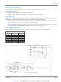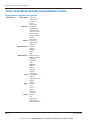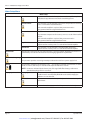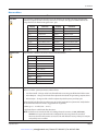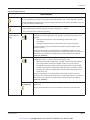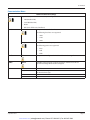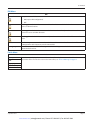
1
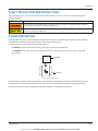
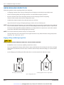
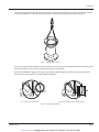
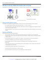
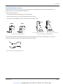
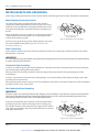
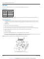
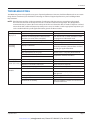
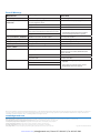
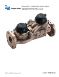
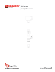
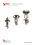
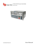
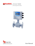
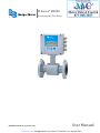
M-Series® M5000
Electromagnetic Flow Meter
MAG-UM-00219-EN-02 (September 2013)
User Manual
www.mvandc.com | [email protected] | Phone: 877.566.3837 | Fax: 925.407.2903
M-Series® M5000 Electromagnetic Flow Meter
Page ii
September 2013
www.mvandc.com | [email protected] | Phone: 877.566.3837 | Fax: 925.407.2903
User Manual
CONTENTS
SAFETY PRECAUTIONS AND INSTRUCTIONS . . . . . . . . . . . . . . . . . . . . . . . . . . . . . . . . . . . . . . . . . . . . . . . . . . . . 5
SYSTEM DESCRIPTION . . . . . . . . . . . . . . . . . . . . . . . . . . . . . . . . . . . . . . . . . . . . . . . . . . . . . . . . . . . . . . . . . . 5
UNPACKING AND INSPECTION . . . . . . . . . . . . . . . . . . . . . . . . . . . . . . . . . . . . . . . . . . . . . . . . . . . . . . . . . . . . . 6
Rigging, Lifting and Moving Large Units . . . . . . . . . . . . . . . . . . . . . . . . . . . . . . . . . . . . . . . . . . . . . . . . . . . . . 6
METER LOCATION, ORIENTATION AND APPLICATIONS . . . . . . . . . . . . . . . . . . . . . . . . . . . . . . . . . . . . . . . . . . . . . . 8
Remote Amplifier Outdoor Location . . . . . . . . . . . . . . . . . . . . . . . . . . . . . . . . . . . . . . . . . . . . . . . . . . . . . . . 8
Pipelines and Fluid Flow . . . . . . . . . . . . . . . . . . . . . . . . . . . . . . . . . . . . . . . . . . . . . . . . . . . . . . . . . . . . . . . 8
Meter Orientation . . . . . . . . . . . . . . . . . . . . . . . . . . . . . . . . . . . . . . . . . . . . . . . . . . . . . . . . . . . . . . . . . . . 9
Vertical Placement . . . . . . . . . . . . . . . . . . . . . . . . . . . . . . . . . . . . . . . . . . . . . . . . . . . . . . . . . . . . . . . . . . 9
Horizontal Placement . . . . . . . . . . . . . . . . . . . . . . . . . . . . . . . . . . . . . . . . . . . . . . . . . . . . . . . . . . . . . . . . 9
Straight Pipe Requirements . . . . . . . . . . . . . . . . . . . . . . . . . . . . . . . . . . . . . . . . . . . . . . . . . . . . . . . . . . . . . 9
Pipe Reducer Requirements . . . . . . . . . . . . . . . . . . . . . . . . . . . . . . . . . . . . . . . . . . . . . . . . . . . . . . . . . . . 10
Chemical Injection Applications . . . . . . . . . . . . . . . . . . . . . . . . . . . . . . . . . . . . . . . . . . . . . . . . . . . . . . . . . 10
Partially-Filled Pipe Situations . . . . . . . . . . . . . . . . . . . . . . . . . . . . . . . . . . . . . . . . . . . . . . . . . . . . . . . . . . . 11
METER GASKETS AND GROUNDING . . . . . . . . . . . . . . . . . . . . . . . . . . . . . . . . . . . . . . . . . . . . . . . . . . . . . . . . . 12
Meter/Pipeline Connection Gaskets . . . . . . . . . . . . . . . . . . . . . . . . . . . . . . . . . . . . . . . . . . . . . . . . . . . . . . 12
Meter Grounding . . . . . . . . . . . . . . . . . . . . . . . . . . . . . . . . . . . . . . . . . . . . . . . . . . . . . . . . . . . . . . . . . . 12
Conductive Pipe Grounding . . . . . . . . . . . . . . . . . . . . . . . . . . . . . . . . . . . . . . . . . . . . . . . . . . . . . . . . . . . 12
Non-Conductive Pipe Grounding . . . . . . . . . . . . . . . . . . . . . . . . . . . . . . . . . . . . . . . . . . . . . . . . . . . . . . . . 12
AMPLIFIER MOUNTING CONFIGURATION OPTIONS . . . . . . . . . . . . . . . . . . . . . . . . . . . . . . . . . . . . . . . . . . . . . . 13
Meter Mount Configuration . . . . . . . . . . . . . . . . . . . . . . . . . . . . . . . . . . . . . . . . . . . . . . . . . . . . . . . . . . . . 13
Remote Mount Configuration . . . . . . . . . . . . . . . . . . . . . . . . . . . . . . . . . . . . . . . . . . . . . . . . . . . . . . . . . . 13
Submersible Option . . . . . . . . . . . . . . . . . . . . . . . . . . . . . . . . . . . . . . . . . . . . . . . . . . . . . . . . . . . . . . . . 13
WIRING . . . . . . . . . . . . . . . . . . . . . . . . . . . . . . . . . . . . . . . . . . . . . . . . . . . . . . . . . . . . . . . . . . . . . . . . . . . 13
Wiring Safety . . . . . . . . . . . . . . . . . . . . . . . . . . . . . . . . . . . . . . . . . . . . . . . . . . . . . . . . . . . . . . . . . . . . . 13
Opening the M5000 Cover . . . . . . . . . . . . . . . . . . . . . . . . . . . . . . . . . . . . . . . . . . . . . . . . . . . . . . . . . . . . 13
BATTERY . . . . . . . . . . . . . . . . . . . . . . . . . . . . . . . . . . . . . . . . . . . . . . . . . . . . . . . . . . . . . . . . . . . . . . . . . . 14
Battery Life . . . . . . . . . . . . . . . . . . . . . . . . . . . . . . . . . . . . . . . . . . . . . . . . . . . . . . . . . . . . . . . . . . . . . . 14
Battery Replacement . . . . . . . . . . . . . . . . . . . . . . . . . . . . . . . . . . . . . . . . . . . . . . . . . . . . . . . . . . . . . . . . 14
Remote Mount Installation . . . . . . . . . . . . . . . . . . . . . . . . . . . . . . . . . . . . . . . . . . . . . . . . . . . . . . . . . . . . 15
September 2013
Page iii
www.mvandc.com | [email protected] | Phone: 877.566.3837 | Fax: 925.407.2903
M-Series® M5000 Electromagnetic Flow Meter
Mount Bracket to Amplifier . . . . . . . . . . . . . . . . . . . . . . . . . . . . . . . . . . . . . . . . . . . . . . . . . . . . . . . . . 15
Wiring Configuration . . . . . . . . . . . . . . . . . . . . . . . . . . . . . . . . . . . . . . . . . . . . . . . . . . . . . . . . . . . . . 15
Wiring for Remote Configuration . . . . . . . . . . . . . . . . . . . . . . . . . . . . . . . . . . . . . . . . . . . . . . . . . . . . . 15
CONFIGURING INPUT/OUTPUT (I/O) . . . . . . . . . . . . . . . . . . . . . . . . . . . . . . . . . . . . . . . . . . . . . . . . . . . . . . . . 16
Circuit Board Diagram . . . . . . . . . . . . . . . . . . . . . . . . . . . . . . . . . . . . . . . . . . . . . . . . . . . . . . . . . . . . . . . 16
Digital Output Wiring Diagrams . . . . . . . . . . . . . . . . . . . . . . . . . . . . . . . . . . . . . . . . . . . . . . . . . . . . . . 17
Digital Output Selections . . . . . . . . . . . . . . . . . . . . . . . . . . . . . . . . . . . . . . . . . . . . . . . . . . . . . . . . . . 17
PROGRAMMING THE M5000 . . . . . . . . . . . . . . . . . . . . . . . . . . . . . . . . . . . . . . . . . . . . . . . . . . . . . . . . . . . . . . 18
Function Buttons . . . . . . . . . . . . . . . . . . . . . . . . . . . . . . . . . . . . . . . . . . . . . . . . . . . . . . . . . . . . . . . . . . 18
Display . . . . . . . . . . . . . . . . . . . . . . . . . . . . . . . . . . . . . . . . . . . . . . . . . . . . . . . . . . . . . . . . . . . . . . . . . 18
Icons . . . . . . . . . . . . . . . . . . . . . . . . . . . . . . . . . . . . . . . . . . . . . . . . . . . . . . . . . . . . . . . . . . . . . . . 18
Battery Levels . . . . . . . . . . . . . . . . . . . . . . . . . . . . . . . . . . . . . . . . . . . . . . . . . . . . . . . . . . . . . . . . . . 18
M5000 MAIN MENU PROGRAMMING OPTIONS . . . . . . . . . . . . . . . . . . . . . . . . . . . . . . . . . . . . . . . . . . . . . . . . . 19
USING THE M5000 MAIN MENU PROGRAMMING OPTIONS . . . . . . . . . . . . . . . . . . . . . . . . . . . . . . . . . . . . . . . . . . 20
Display Menu Screen Hierarchy Structure . . . . . . . . . . . . . . . . . . . . . . . . . . . . . . . . . . . . . . . . . . . . . . . . . . . 20
SECURITY . . . . . . . . . . . . . . . . . . . . . . . . . . . . . . . . . . . . . . . . . . . . . . . . . . . . . . . . . . . . . . . . . . . . . . . . . . 21
Setting a PIN . . . . . . . . . . . . . . . . . . . . . . . . . . . . . . . . . . . . . . . . . . . . . . . . . . . . . . . . . . . . . . . . . . . . . 21
Logging In . . . . . . . . . . . . . . . . . . . . . . . . . . . . . . . . . . . . . . . . . . . . . . . . . . . . . . . . . . . . . . . . . . . . . . . 21
Logging Out . . . . . . . . . . . . . . . . . . . . . . . . . . . . . . . . . . . . . . . . . . . . . . . . . . . . . . . . . . . . . . . . . . . . . 21
Meter Setup Menu . . . . . . . . . . . . . . . . . . . . . . . . . . . . . . . . . . . . . . . . . . . . . . . . . . . . . . . . . . . . . . . . . 22
Measure Menu . . . . . . . . . . . . . . . . . . . . . . . . . . . . . . . . . . . . . . . . . . . . . . . . . . . . . . . . . . . . . . . . . . . . 23
Inputs/Outputs Menu . . . . . . . . . . . . . . . . . . . . . . . . . . . . . . . . . . . . . . . . . . . . . . . . . . . . . . . . . . . . . . . 25
Communication Menu . . . . . . . . . . . . . . . . . . . . . . . . . . . . . . . . . . . . . . . . . . . . . . . . . . . . . . . . . . . . . . . 27
Miscellaneous Menu . . . . . . . . . . . . . . . . . . . . . . . . . . . . . . . . . . . . . . . . . . . . . . . . . . . . . . . . . . . . . . . . 28
Information Menu . . . . . . . . . . . . . . . . . . . . . . . . . . . . . . . . . . . . . . . . . . . . . . . . . . . . . . . . . . . . . . . . . . 28
PIN Menu . . . . . . . . . . . . . . . . . . . . . . . . . . . . . . . . . . . . . . . . . . . . . . . . . . . . . . . . . . . . . . . . . . . . . . . 29
Faults Menu . . . . . . . . . . . . . . . . . . . . . . . . . . . . . . . . . . . . . . . . . . . . . . . . . . . . . . . . . . . . . . . . . . . . . . 29
MAINTENANCE . . . . . . . . . . . . . . . . . . . . . . . . . . . . . . . . . . . . . . . . . . . . . . . . . . . . . . . . . . . . . . . . . . . . . . 30
Cleaning the Flow Tube and Electrode . . . . . . . . . . . . . . . . . . . . . . . . . . . . . . . . . . . . . . . . . . . . . . . . . . . . . 30
TROUBLESHOOTING . . . . . . . . . . . . . . . . . . . . . . . . . . . . . . . . . . . . . . . . . . . . . . . . . . . . . . . . . . . . . . . . . . . 31
Errors & Warnings . . . . . . . . . . . . . . . . . . . . . . . . . . . . . . . . . . . . . . . . . . . . . . . . . . . . . . . . . . . . . . . . . . 32
Page iv
September 2013
www.mvandc.com | [email protected] | Phone: 877.566.3837 | Fax: 925.407.2903
User Manual
SAFETY PRECAUTIONS AND INSTRUCTIONS
Some procedures in this manual require special safety considerations. In such cases, the text is emphasized with the
following symbols:
Symbol
Explanation
Warning indicates the potential for severe personal injury, death or substantial property damage.
Comply with the instructions and proceed with care.
Caution indicates the potential for minor personal injury or property damage. Comply with the
instructions and proceed with care.
SYSTEM DESCRIPTION
The Badger Meter M-Series® model M5000 electromagnetic flow meter is intended for fluid metering in most industries
including water, wastewater, food and beverage, pharmaceutical and chemical.
The basic components of an electromagnetic flow meter are:
•
The detector, which includes the flow tube, isolating liner and measuring electrodes.
•
The amplifier, which is the electronic device responsible for the signal processing, flow calculation, display and
output signals.
Amplifier
®
Detector
Figure 1: Amplifier and Detector
The construction materials of the wetted parts (liner and electrodes) should be appropriate for the specifications on the
intended type of service. We recommend that you review all of the compatibilities consistent with the specifications.
Each meter is factory tested and calibrated. A calibration certificate is included with each meter.
September 2013
Page 5
www.mvandc.com | [email protected] | Phone: 877.566.3837 | Fax: 925.407.2903
M-Series® M5000 Electromagnetic Flow Meter
UNPACKING AND INSPECTION
Follow these guidelines when unpacking the M-Series equipment.
•
If a shipping container shows any sign of damage, have the shipper present when you unpack the meter.
•
Follow all unpacking, lifting and moving instructions associated with the shipping container.
•
Open the container and remove all packing materials. Store the shipping container and packing
materials in the event the unit needs to be shipped for service.
•
Verify that the shipment matches the packing list and your order form.
•
Inspect the meter for any signs of shipping damage, scratches, or loose or broken parts.
NNOTE: If the unit was damaged in transit, it is your responsibility to request an inspection report from the carrier within 48
hours. You must then file a claim with the carrier and contact Badger Meter for appropriate repairs or replacement.
•
All detectors with polytetrafluoroethylene (PTFE) liners are shipped with a liner protector on each end to maintain
proper form of the PTFE material during shipping and storage.
NNOTE: Do not remove the liner protectors until you are ready to install.
•
Storage: If the meter is to be stored, place it in its original container in a dry, sheltered location. Storage temperature
ranges are: –40…160° F (–40…70° C).
Rigging, Lifting and Moving Large Units
WHEN RIGGING, LIFTING OR MOVING LARGE UNITS, FOLLOW THESE GUIDELINES:
•
DO NOT lift or move a meter by its amplifier, junction box or cables.
•
Use a crane rigged with soft straps to lift and move meters with flow tubes that are between two inches and eight
inches (50 mm and 200 mm). Place the straps around the detector body, between the flanges, on each side of the
detector.
•
Use the lifting lugs when lifting meter flow tubes that are 10 inches (250 mm) in diameter or larger.
®
®
Place straps between flanges.
Use lifting lugs with 10-inch or larger meters.
Figure 2: Rigging Large Units
Page 6
September 2013
www.mvandc.com | [email protected] | Phone: 877.566.3837 | Fax: 925.407.2903
User Manual
•
Use the sling-rigged method to lift large detectors into a vertical position while they are still crated. Use this method
to position while they are still crated. Use this method to position large detectors vertically into pipelines.
Figure 3: Sling-Rigged Lifting Methods
•
Do not lift a detector with a forklift by positioning the detector body on the forks, with the flanges extending beyond
the lift. This could dent the housing or damage the internal coil assemblies.
•
Never place forklift forks, rigging chains, straps, slings, hooks or other lifting devices inside or through the detector's
flow tube to hoist the unit. This could damage the isolating liner.
Do not lift detector with forklift.
Do not lift or rig lifting devices through detector.
Figure 4: Lifting and Rigging Cautions
September 2013
Page 7
www.mvandc.com | [email protected] | Phone: 877.566.3837 | Fax: 925.407.2903
M-Series® M5000 Electromagnetic Flow Meter
METER LOCATION, ORIENTATION AND APPLICATIONS
The M5000 provides two amplifier mounting options: an integral or meter mount option and a junction box/remote option.
Meter mount amplifier
Junction box with remote amplifier
Figure 5: Amplifier Mounting Options
Remote Amplifier Outdoor Location
The amplifier can be installed and operated outdoors. However, it must be protected from the elements, as follows:
•
The ambient environment/temperature rating for the unit is –4…140° F (–20…60° C).
•
If an indoor location is within 100 feet (30 meters) of the detector, consider increasing the cable length (up to 100 ft)
and mounting the amplifier indoors.
•
At minimum, fabricate a roof or shield over and/or around the amplifier to protect the LCD display screen from direct
sunlight.
Pipelines and Fluid Flow
Take the following precautions during installation:
•
Do not install the meter on pipes with extreme pipe vibrations. If pipes are vibrating, secure the piping with
appropriate pipe supports in front of and behind the meter. If vibrations cannot be restrained, mount the amplifier in
a remote location.
•
Do not install the detector close to pipeline valves, fittings or impediments that can cause flow disturbances.
•
For detectors with PTFE liners, do not install the detector on suction sides of pumps.
•
Do not install the detector on outlet sides of piston or diaphragm pumps. Pulsating flow can affect meter
performance.
•
Avoid installing the detector near equipment that produces electrical interference such as electric motors, transformers,
variable frequency, and power cables.
•
Verify that both ends of the signal cables are securely fastened.
•
Place power cables and signal cables in separate conduits.
•
Place the meter where there is enough access for installation and maintenance tasks.
Page 8
September 2013
www.mvandc.com | [email protected] | Phone: 877.566.3837 | Fax: 925.407.2903
User Manual
Meter Orientation
Mag meters can operate accurately in any pipeline orientation and can measure volumetric flow in forward and reverse
directions.
NNOTE: A "Forward Flow" direction arrow is printed on the detector label.
Vertical Placement
Mag meters perform best when placed vertically, with liquid flowing upward and meter electrodes in a closed, full pipe.
Figure 6: Vertical Placement
Vertical placement allows the pipe to remain completely full, even in low flow, low pressure applications, and it prevents
solids build-up, sediment deposit and accumulation on the liner and electrodes.
NNOTE: Carefully observe the “Forward Flow” label on the meter body and install the meter accordingly. When installed
vertically, rotate amplifier so that cable glands are facing down.
Horizontal Placement
Electrode
M5000 meters are equipped with an Empty Pipe
Plane
Detection feature. If an electrode mounted in the pipe
Electrode
is not covered by fluid for five seconds, the meter will
Plane
display an Empty Pipe Detection condition. The meter
will send out an error message and stop measuring
RIGHT
WRONG
flow. When the electrode is again covered with fluid,
Figure 7: Horizontal Placement
the error message disappears and the meter will begin
measuring.
When installing the meter on a horizontal pipe, mount the detector to the pipe with the flow-measuring electrode axis in a
horizontal plane (three and nine o’clock). This placement helps prevent solids build-up, sediment deposit and accumulation
on the electrodes.
Straight Pipe Requirements
Sufficient straight-pipe runs are required at the
detector inlet and outlet for optimum meter accuracy
and performance. An equivalent of three diameters of
straight pipe is required on the inlet (upstream) side. Two
diameters are required on the outlet (downstream) side.
FLOWMETER
D (Pipe Size)
D (Pipe Size)
FORWARD FLOW
ELBOW
TEE
GATE VALVE
(FULLY OPEN)
CHECK VALVE
GLOBE VALVE
BUTTERFLY VALVE
PUMP
3xD
2xD
MINIMUM STRAIGHT PIPE
MINIMUM STRAIGHT PIPE
7xD
MINIMUM STRAIGHT PIPE
STANDARD CONCENTRIC
REDUCERS
(NO DISTANCE REQUIRED)
ELBOW
TEE
ANY VALVE
MINIMUM PIPING REQUIREMENT
Figure 8: Straight Pipe Requirements
September 2013
Page 9
www.mvandc.com | [email protected] | Phone: 877.566.3837 | Fax: 925.407.2903
M-Series® M5000 Electromagnetic Flow Meter
Pipe Reducer Requirements
With pipe reducers, a smaller meter can be mounted in larger pipelines. This arrangement may increase low-flow accuracy.
There are no special requirements for standard, concentric, pipe reducers.
Custom fabricated pipe reducers must have an approximate slope angle of 15 degrees to minimize flow disturbances and
excessive loss of head. If this is not possible, install the custom pipe reducers as if they were fittings and install the required
amount of straight pipe
Figure 9: Pipe Reducer Requirements
Chemical Injection Applications
For water line applications with a chemical injection point, install the meter upstream of the injection point. This eliminates
any meter performance issues.
Figure 10: Chemical Injection Point Upstream of Meter
If a meter must be installed downstream of a chemical injection connection, the distance between the meter and the
injection point should be between 50 and 100 feet (15 and 30 meters). The distance must be long enough to allow the water
or chemical solution to reach the meter in a complete, homogeneous mixture.
Figure 11: Chemical Injection Point Upstream of Meter
If the injection point is too close, the meter senses the two different conductivities for each liquid. This will likely result in
inaccurate measurements. The injection method—spaced bursts, continuous stream of drips or liquid or gas—can also affect
downstream readings by the meter.
Page 10
September 2013
www.mvandc.com | [email protected] | Phone: 877.566.3837 | Fax: 925.407.2903
User Manual
Partially-Filled Pipe Situations
In some locations, the process pipe may be momentarily only partially filled. Examples include: lack of back pressure,
insufficient line pressure and gravity flow applications.
To eliminate these situations:
• Do not install the meter at the highest point of the pipeline.
• Do not install the meter in a vertical, downward flow section of pipe.
• Always position the ON/OFF valves on the downstream side of the meter.
RIGHT
WRONG
FLOW
RIGHT
FLOW
FLOW
FLOW
WRONG
Do not install in a vertical, downward position.
Figure 12: Incorrect Meter Placement
Position "On/Off" valves on downstream side.
Figure 13: Position Valves on Downstream Side
To minimize the possibility of partially-full pipe flows in horizontal, gravity or low pressure applications, create a pipe
arrangement that ensures the detector remains full of liquid at all times.
Figure 14: Pipe Positioned to Keep Water in Detector
September 2013
Page 11
www.mvandc.com | [email protected] | Phone: 877.566.3837 | Fax: 925.407.2903
M-Series® M5000 Electromagnetic Flow Meter
METER GASKETS AND GROUNDING
Gasket and grounding requirements must be considered when determining the meter location, orientation and application.
Meter/Pipeline Connection Gaskets
You must install gaskets (not provided) between the detector's
isolating liner and the pipeline flange to ensure a proper and secure
hydraulic seal. Use gaskets that are compatible with the fluid. Center
each gasket on the flange to avoid flow restrictions or turbulence in
the line.
During installation, do not use graphite or any electrically conductive
sealing compound to hold the gaskets. This could compromise the
accuracy of the measuring signal.
GASKETS RECOMMENDED
Figure 15: Meter/Pipeline Connection Gaskets
If you are using a grounding ring in the detector/pipeline connection,
place the ring between two gaskets. (See "Non-Conductive Pipe
Grounding" on page 12.)
Meter Grounding
Process pipeline material can be either electrically conductive (metal) or not electrically conductive (made of or lined with
PVC, fiberglass or concrete).
IIMPORTAN
It is essential that the mag meter amplifier’s input ground (zero voltage reference) be electrically connected to the liquid media and
to a good, solid earth ground reference.
Conductive Pipe Grounding
To achieve an adequate ground, the meter body MUST be electrically connected to the liquid media. The mag meter flanges
are provided with grounding bolts for this purpose.
If the pipe material is electrically conductive, simply install grounding straps between these grounding bolts and the
mating flanges.
To ensure a good electrical connection at the mating flanges, we recommend that you drill and tap the flanges and install a
grounding screw (not provided).
These grounding straps must be copper wire, at least 12 AWG size. They must be connected on both sides (inlet and outlet) of
the detector and to a local, earth ground.
Non-Conductive Pipe Grounding
IIMPORTAN
If the process pipe is not electrically conductive (PVC, fiberglass, cement-lined pipes or any other non-conductive material) and the
meter was not originally ordered with an optional grounding electrode, you must install a pair of grounding rings between the
mating flanges at both ends of the meter. See the following illustration.
In this case, the grounding straps should be connected to both of the
grounding rings and to a good, solid earth ground. Grounding rings
are available in stainless steel. If your fluid is too aggressive for stainless
steel, order a meter with the optional grounding electrode in a material
compatible with the fluid.
GROUNDING RING
GROUNDING RING
GASKETS RECOMMENDED
Figure 16: Non-Conductive Pipe Grounding
Page 12
September 2013
www.mvandc.com | [email protected] | Phone: 877.566.3837 | Fax: 925.407.2903
User Manual
AMPLIFIER MOUNTING CONFIGURATION OPTIONS
Meter Mount Configuration
The meter mount configuration has the amplifier mounted directly on the detector. This compact, self-contained
configuration minimizes installation wiring.
Remote Mount Configuration
The remote mount configuration places the amplifier at a location away from the fluid flow and detector. This is necessary in
situations where process fluid temperature or the environment exceeds amplifier ratings.
The detector and amplifier are connected by wires, run through conduit, between junction boxes on the detector and the
amplifier. The distance between the detector junction box and amplifier junction box can be up to 100 feet (30 meters). A
remote mounting bracket is supplied.
Submersible Option
If you are installing the meter in a vault, you should order the remote amplifier option. You must not install the amplifier inside
a vault. We also recommend ordering the remote meter package with the submersible option (NEMA 6P). This will eliminate
any potential problems resulting from humidity or temporary flooding in the vault.
NNOTE: NEMA 6P enclosures are constructed for indoor or outdoor use to provide protection against access to hazardous
parts; to provide a degree of protection against ingress of solid foreign objects and water (hose directed water and
the entry of water during prolonged submersion at a limited depth); that provide an additional level of protection
against corrosion and that will be undamaged by the external formation of ice on the enclosure.
WIRING
Wiring Safety
AT INSTALLATION, BE SURE TO COMPLY WITH THE FOLLOWING REQUIREMENTS:
• Disconnect power to the unit before attempting any connection or service to the unit.
• Do not bundle or route signal lines with power lines.
• Keep all lines as short as possible.
• Use twisted pair shielded wire for all output wiring.
• Observe all applicable, local electrical codes.
Opening the M5000 Cover
The M5000 amplifier's design lets you open the cover
without completely removing it.
Follow these steps:
1. Completely remove the top two screws from the
amplifier using a blade/slotted screwdriver.
2. Loosen both of the bottom screws so that the round
head of each screw clears the top face of the cover.
3. Pull the cover down to the open position.
Figure 17: Remove Two Screws
Figure 18: Open the Cover
September 2013
Page 13
www.mvandc.com | [email protected] | Phone: 877.566.3837 | Fax: 925.407.2903
M-Series® M5000 Electromagnetic Flow Meter
BATTERY
Use a two D-cell battery pack (1/2" to 6") or a double two D-cell battery pack (8" to 24").
Battery Life
Standard Pack
Sampling
Expected Life
0.25
3 months
4
4 years
8
8 years
15
10 years
These calculations are for a standard battery pack, with two D-size batteries, with communication and outputs OFF, at a
temperature of 77º F (25º C).
Battery Replacement
1. Go to Main Menu > Misc > Battery > Change and select the capacity of the battery pack which should be installed
(see label on the battery pack 19 Ah, 38 Ah or 70 Ah). Press E to quit. The display freezes (no reaction by pressing
any button).
2. Open the cover.
3. Remove all connectors (detector and outputs).
4. Remove all 4 screws of the main board, remove the circuit board and disconnect the old battery.
5. Remove the old battery and wait about 2 minutes before replacing it with a new one (LCD display should be off ).
6. Plug the battery connector into the back of the main board and reinstall the circuit board.
7. Replace all the plugs.
8. Close the cover tight.
9. Check time and date (Main Menu > Misc > Time and Main Menu > Misc > Date DMY).
10.Check capacity of battery (Main Menu > Misc > Battery AH). The first value is the used capacity, which should be 0.0. The
second value is the capacity of the battery pack. Battery AH is a read-only parameter.
NNOTE: Totalizers and configuration remain unaffected during battery replacement.
Figure 19: Amplifier Housing Components – Exploded View
Page 14
September 2013
www.mvandc.com | [email protected] | Phone: 877.566.3837 | Fax: 925.407.2903
User Manual
Remote Mount Installation
If you are installing the M5000 amplifier in a remote location, review the procedures in this section.
Mount Bracket to Amplifier
1. Align bracket-mounting holes with amplifier mounting holes.
2. Attach bracket to amplifier with supplied screws. Torque the screws to 80 inch-pounds.
Wiring Configuration
Wiring between the detector and the M5000 amplifier comes complete from the factory. If your installation requires the use
of conduit, we recommend that you follow these steps when wiring the detector to the amplifier.
1. Carefully remove the wires connected to the terminal blocks that run to the M5000 amplifier or to the junction box.
See the chart below for a reference of wire color to terminal connection.
2. Run cable through the conduit while retaining the wiring of the cable to the amplifier or the junction box, as supplied.
3. Complete conduit assembly on both ends and rewire the cable as it was previously wired.
Wiring for Remote Configuration
Remote style M5000 amplifier models can be ordered with standard cables measuring 15, 30, 50 and 100 feet.
Junction Box
Connection
No.
11
12
13
40
44*
44*
45
46
Description
Wire Color
Coil
Coil
Main Shield
Empty Pipe
Shield
Empty Pipe Shield
Electrode
Electrode
Red/Brown
Blue/White
Not Used
Pink
Green
Shield Wire
White
Black
*Connections with the No. 44 are lying on the same potential.
M5000 AMPLIFIER
Figure 20: Wiring for Remote Configuration
September 2013
Page 15
www.mvandc.com | [email protected] | Phone: 877.566.3837 | Fax: 925.407.2903
M-Series® M5000 Electromagnetic Flow Meter
CONFIGURING INPUT/OUTPUT (I/O)
This section describes wiring the following M5000 outputs:
•
Digital outputs
•
Communication
When the sensor and the amplifier have been wired, wire any outputs to the M5000 amplifier.
Follow all of the safety precautions and local code to prevent electrical shock and damage to the electronic components.
Circuit Board Diagram
Figure 21: Configuring Input/Output
Input/Output
Description
Terminal
Output 1
Passive max. 30V DC, 20 mA
Max. Frequency 100 Hz
OUT1 (+) and (–)
Output 2
Passive max. 30V DC, 20 mA
Max. Frequency 100 Hz
OUT2 (+) and (–)
Output 3
Passive Max 30V DC, 20 mA
OUT3 (+) and (–)
Output 4
Passive Max 30V DC, 20 mA
OUT4 (+) and (–)
Can be used with digital input as an ADE interface.
RS232
Modbus RTU
RxD, TxD, GND
IN
Digital input 3…35V DC
IN (+) and (–)
M-BUS
M-Bus interface
No polarity
Page 16
September 2013
www.mvandc.com | [email protected] | Phone: 877.566.3837 | Fax: 925.407.2903
User Manual
Digital Output Wiring Diagrams
Positive Pulse Logic
Negative Pulse Logic
Figure 22: Digital Output Wiring Diagram
Digital Output Selections
Output 1
Forward Pulse Output
Output 2
Output 3
Reverse Pulse Output
Flow direction
(Forward vs. Reverse)
Flow Setpoint
(0…100% of full scale, resolution 1%)
Flow Setpoint
(0…100% of full scale, resolution 1%)
Empty pipe alarm
Empty pipe alarm
Error alarm
Error alarm
Output 4
ADE
Off
Test
Can be used with AMR when the pulse width is set to
50 milliseconds.
—
Outputs are configurable for Pulses/Unit (PPU) and Pulse Width (PW). The PW is configurable from 5…500 milliseconds, with a
frequency limit is 100 Hz. The PPU is displayed using an automatically selected resolution.
The high/low flow alarm functionality is configurable for maximum and minimum setpoints as a percentage of full-scale flow.
Configurable values are settable from 0…100% in 1% increments.
September 2013
Page 17
www.mvandc.com | [email protected] | Phone: 877.566.3837 | Fax: 925.407.2903
M-Series® M5000 Electromagnetic Flow Meter
PROGRAMMING THE M5000
The M5000 amplifier is pre-programmed from the factory. No additional programming is necessary, however, for special
features, the meter can be programmed for specific requirements.
Function Buttons
All M5000 programming is accomplished using the three function buttons located on the
front of the amplifier. Screen navigation and digit and parameter selection is performed by a
combination of these three buttons.
The up-arrow button allows scrolling through seven menu screens. This button is also used to advance numerical digits to
change values, such as frequency, period, and EP level as well as toggle on-off conditions and flow directions.
The right-arrow button allows digit selection from left to right and allows selecting either the top row of the display or the
bottom row (the bottom row is active when flashing).
The EXIT SAVE button allows the saving of changed values and conditions, toggling between the upper and lower display
lines and returning to a previous menu.
Display
The top row displays seven digits for specific values on each screen and the bottom row
displays meter and register condition icons and current screen descriptions.
Icons
Battery status
Communication interface is activated (RS232, IrDA, M-Bus)
Meter is unlocked
Error message
Empty pipe detection
Battery Levels
The battery icon indicates three levels of capacity:
Greater than 3 volts (maximum = 3.6V)
Greater than 2 volts, less than 3 volts (recommended battery replacement)
Less than 2 volts (measuring has stopped)
Page 18
September 2013
www.mvandc.com | [email protected] | Phone: 877.566.3837 | Fax: 925.407.2903
User Manual
M5000 MAIN MENU PROGRAMMING OPTIONS
The following M5000 programming options are available from the Main Menu:
•
Meter Setup
•
Measure
•
In/Out
•
Communication
•
Miscellaneous
•
Information
•
Pin
•
Faults
The applicable security level for each menu option is indicated as follows:
A
S
U
Administrative
Service
User
Parameters indicated by the battery icon, if changed, will affect battery performance.
September 2013
Page 19
www.mvandc.com | [email protected] | Phone: 877.566.3837 | Fax: 925.407.2903
M-Series® M5000 Electromagnetic Flow Meter
USING THE M5000 MAIN MENU PROGRAMMING OPTIONS
Display Menu Screen Hierarchy Structure
Main_Menu →
Meter Setup → Calibration
Scale Factor
Frequency
Period
Empty Pipe
Measure → Flow Unit
Totalizer Unit
Full Scale Flow
Low Flow Cutoff
Flow Direction
Totalizer1 Reset
Median
Filter Display
In/Out → Simulation
Digital Input
Outputs
Communication → Interface
RS-232
MODBUS
M-Bus
ADE
Miscellaneous → Battery Voltage
Battery Capacity
Language
Date DMY
Time
EEPROM
Battery
Restart
HDD Free
Polar[V]
Datalogger
Info → Serial Number
Version
Compilation Date
OtpCrc
AppCrc
PINs → Control
User
Service
Admin
Random
Emergency
Faults → Preamp
Coil
Empty Pipe
Measure Time
Voltage Overflow
Page 20
September 2013
www.mvandc.com | [email protected] | Phone: 877.566.3837 | Fax: 925.407.2903
User Manual
SECURITY
The M5000 security feature allows the option to restrict access to the meter by way of a 6-digit Personal Identification Number
(PIN). The system administrator can set up a single PIN for each of the three different levels of access:
•
Administration – allows access to all M5000 menu configuration screens.
•
Service – allows access to service-level and user-level menu configuration screens.
•
User – allows access only to user-level menu configuration screens.
NNOTE: For a lost PIN, Contact Badger Meter Technical Support at 800-456-5023 for a replacement PIN.
Not all levels of access need to be set. If no PINs are set up, any M5000 user will have access to all functions.
NNOTE: The security settings will also apply to remote access. All remote writes via Modbus to the meter will be blocked
unless the user is remotely logged in.
Setting a PIN
1. From the Main Menu, press the right-arrow button.
2. From the Meter Setup menu, press the up-arrow button until the Pin menu is displayed.
3. Press the right-arrow button to display the PINS Control menu.
4. Press the right-arrow button to flash ON or OFF.
5. With either ON or OFF flashing, press the up-arrow button to display ON.
6. Press the EXIT SAVE button to save the ON setting.
7. With the Control menu flashing, press the up-arrow button to display the desired security level (user, service,
or admin).
8. With the desired security level flashing, press the right-arrow button to display the upper row of six zeros (digits).
9. Press the up-arrow button to change the first digit, followed by pressing the right-arrow button to select the
next digit.
10.Press the EXIT SAVE button to save the PIN number for that security level.
The saved PIN number will be the same PIN number used to log in to the amplifier.
NNOTE: Be sure to log off when you have completed work with the M5000. Otherwise, a five-minute time delay occurs
between the most recent activity and the time when the M5000 automatically logs off.
Logging In
To change any parameter in the mag meter, the PIN entered must provide the proper security privilege required by
the parameter.
To enter a PIN, go to the Login menu and enter the PIN for the required security level.
Once you are properly logged in, the unlocked icon appears on the meter display.
NNOTE: A PIN Error message displays if the incorrect PIN is entered.
Logging Out
To log out, follow steps 1 through 8 under Setting a PIN. At step 9, enter an unknown PIN, then press EXIT SAVE.
September 2013
Page 21
www.mvandc.com | [email protected] | Phone: 877.566.3837 | Fax: 925.407.2903
M-Series® M5000 Electromagnetic Flow Meter
Meter Setup Menu
Meter Setup
Calibration
Diameter
A
Detector Factor
A
Detector Zero
A
This parameter is set at the factory. In the event the amplifier is replaced,
verify that the pipe diameter matches the installed pipe size.
This parameter is set at the factory. This factor compensates for accuracy
error as a result of the installed detector.
In the event the amplifier is replaced, this parameter must be
reprogrammed with the original detector zero.
This parameter is set at the factory.
This parameter compensates for accuracy error as a result of the installed
detector.
In the event the amplifier is replaced, this parameter must be
reprogrammed with the original detector factor.
Amplifier Factor
This parameter is set at the factory and is Read Only. This factor
compensates for accuracy error as a result of the installed amplifier.
Coil Current
This parameter is set at the factory and is Read Only. This factor
compensates for accuracy error as a result of the installed amplifier.
Changing the scale factor lets you adjust the meter´s accuracy without disturbing parameters set
by the factory. You can tune the meter to meet changing application requirements.
Scale Factor
S
Power Line Frequency This parameter is set at the factory.
This parameter provides measuring immunity to industrial noise from a power supply feed.
S
Period
This parameter configures the frequency (1/4, 1…99 seconds) of sampled measurements. In other
words, if set to 15, then every 15 seconds it will sample for 208 micro seconds.
A
Empty Pipe Detection
NNOTE: Parameters indicated by the battery icon, if changed will affect battery performance.
Standard sampling period is 15 seconds.
Empty Pipe ON/OFF
When set to ON, an Empty Pipe condition indicates to the outputs
that the meter is not completely filled. When set to OFF, empty pipe
conditions are not detected.
S
Threshold
S
Measure
This parameter is set at the factory and adjusted to the conductivity of
normal water.
Measures the real empty pipe value. This parameter is Read Only.
Page 22
September 2013
www.mvandc.com | [email protected] | Phone: 877.566.3837 | Fax: 925.407.2903
User Manual
Measure Menu
Measure
Flow Unit
U
This parameter establishes the unit of measure for the flow rate and full scale flow. Changing this
parameter readjusts the full scale flow parameter. For example, changing from GPM to GPS would
change the full scale flow from 60 gal/min to 1 gal/s.
Display
gal/s
Gallons/Sec.
L/min
Liters/Minute
gal/min
Gallons/Min.
L/h
Liters/Hour
gal/h
Gallons/Hour
m /s
Cubic Meters/Sec.
MG/d
MillionGallons/Day
3
m /min
Cubic Meters/Min.
IG/s
ImperialGallons/Sec.
m /h
Cubic Meters/Hour
IG/min
ImperialGallons/Min.
ft /s
Cubic Feet/Sec.
IG/h
ImperialGallons/Hour
ft /m
Cubic Feet/Min.
oz/min
Ounce/Min
ft /h
Cubic Feet/Hour.
bbl/min
Barrel/Min
3
3
3
Full Scale Flow
S
Flow Unit
Liters/Second
3
U
Display
L/s
3
Totalizer Unit
Flow Unit
This parameter establishes the units of measure for the totalizers.
Display
Totalizer Unit
L
Liters
hL
Hectoliter
m3
Cubic Meters
ft
Cubic Feet
3
gal
U.S. Gallons
MG
Million Gallons
IG
Imperial Gallons
bbl
Barrel
oz
Fluid Ounces
ac/ft
Acre per foot
This parameter sets the maximum flow that the system is expected to measure. This parameter has
influence on other system parameters, which include:
• Low Flow Cutoff – Changes to full scale flow affect the measuring cut-off threshold of the meter
• Alarm Outputs – Changes to full scale flow adjusts the thresholds for generating setpoint alarms
• Pulse Outputs – Changes to full scale flow adjusts the pulse frequency and duty cycle
Change the full scale flow based on the meter size and the application’s requirements. Verify that the
full scale flow falls within the meter’s suggested flow range limits.
Flow Range: 0.1…32.8 ft/s (0.03…10 m/s)
The full scale flow is valid for both flow directions.
NNOTE: If the flow rate exceeds the full scale setting of more than 100%, a FLOW_OVERLOAD_
WARNING message indicates that the configured full scale range has been exceeded.
However, the meter will continue to measure. This will affect the latency of the pulse outputs
and possibly cause overflow.
September 2013
Page 23
www.mvandc.com | [email protected] | Phone: 877.566.3837 | Fax: 925.407.2903
M-Series® M5000 Electromagnetic Flow Meter
Measure
Low Flow Cutoff
U
Flow Direction
S
Low flow cutoff defines the threshold at which flow measurement will be forced to zero. The cutoff
value can be set from 0% to 10% of the full scale flow. Increasing this threshold will help prevent false
readings during “no flow” conditions possibly caused by pipe vibration or inherent system noise.
This parameter allows setting the meter to measure forward flow only (unidirectional) or both forward
and reverse flow (bidirectional).
Unidirectional
Flow is totalized in only one direction. The flow direction is indicated by the arrow printed on the
detector label. Unidirectional measurements on the main display screen include:
T1: Registers forward flow, resettable by menu or Modbus RTU.
T2: Registers forward flow, non-resettable.
Bidirectional
Flow is totalized in both directions. Bidirectional measurements on the main display screen include:
T1+: Registers forward flow, resettable by menu or Modbus RTU
T1-: Registers reverse flow, resettable by menu or Modbus RTU
T1N: Registers total flow, T+ - T-, resettable by menu or Modbus RTU
T2+: Registers forward flow, non-resettable
T2-: Registers reverse flow, non-resettable
T1 Reset
T2N: Registers total flow, T+ - T-, non-resettable
This parameter allows the reset of totalizer T1.
S
Median
Filter Display
This parameter can be set to ON or OFF. When set to ON, the median display filters out the flow rate
fluctuations displayed on the LCD.
This parameter can be set from 0…99 seconds. The display will update less frequently, depending on
how high the filter display is set.
Page 24
September 2013
www.mvandc.com | [email protected] | Phone: 877.566.3837 | Fax: 925.407.2903
User Manual
Inputs/Outputs Menu
Inputs/Outputs
Flow Simulation
Flow Simulation provides output simulation based on a percentage of the full scale flow. Simulation
will not accumulate the totalizers. The range of simulation includes –100…100% of the full scale flow.
S
The Flow Simulation Parameter lets you set the range of simulation in increments of 50 (OFF, 0, 50, 100,
-50, -100). The factory default is OFF.
• Digital input lets you reset totalizers or interrupt flow measurement.
Digital Input
• Input switching is provided by applying an external voltage of 3…35V DC.
S
Digital Outputs
(continued on next
page)
• Use a “normally open” contact for operating.
Pulse/Unit
This parameter lets you set how many pulses per unit of measure will be
transmitted to remote applications. For example, assuming the unit of measure
is gallons:
S
• Setting the Pulses/Unit to 1 (standard setting) will transmit 1 pulse
every gallon
• Setting the Pulses/Unit to 0.01 will transmit 1 pulse every 100 gallons
You must configure pulses/unit if the function of the selected output is to be
forward or reverse .
This parameter must be considered with the Pulse Width and Full Scale Flow
parameters. The maximum pulse frequency is 100 Hz. The frequency is correlated
with the flow rate. Violation of output frequency limits will generate a PULSE_
OVERLOAD_WARNING.
Width
This parameter establishes the ON duration of the transmitted pulse. The
configurable range is 0…500 ms. The factory default is 0 ms.
S
• Non-zero pulse width configuration – the OFF duration of the transmitted
pulse is dependent on flow rate. The OFF duration is to be at least the
configured ON duration. At full scale flow, the ON duration equals the Off
duration. The maximum configurable output frequency is limited to 100 Hz.
• The duty cycle of the transmitted pulse is at 50% of the output frequencies
greater than 1 Hz.
This parameter must be considered with the Pulses/Unit and Full Scale Flow
parameters. The maximum pulse frequency is 100 Hz. The frequency is correlated
with the flow rate. Violation of output frequency limits will generate a PULSE_
OVERLOAD_WARNING.
Power
Line Frequency
S
This parameter provides measuring immunity to industrial noise from a power
supply feed.
This parameter should be set to your nominal line frequency, typically 50 Hz.
September 2013
Page 25
www.mvandc.com | [email protected] | Phone: 877.566.3837 | Fax: 925.407.2903
M-Series® M5000 Electromagnetic Flow Meter
Inputs/Outputs
Digital Outputs
(continued)
Set Min.
S
Set Max.
S
[Out 1 Func]
[Out 2 Func]
[Out 3 Func]
[Out 4 Func]
S
This parameter establishes, as a percentage of full scale flow, the threshold at
which the output alarm will be activated. Flow rates below the threshold will
activate the output alarm.
This parameter establishes, as a percentage of full scale flow, the threshold at
which the output alarm will be activated. Flow rates above the threshold will
activate the output alarm.
This parameter provides configuration of the functional operation of the
associated output. The following operations are supported:
Function
Off
Test
MinMax
Empty
ErAlarm
Forward
Reverse
Direct
ADE
Dig1
X
X
X
X
X
X
Dig2
X
X
X
X
X
X
Dig3
X
X
X
X
X
Dig4
X
X
• Inactive [Off ] means digital output is switched off. It is recommended
to switch off the outputs in the menu “Output function” if not used. This
increase the battery life time.
• Test [Test] triggers the output.
• Flow setpoint [MinMax] provides indication when flow rate exceeds
thresholds defined by flow setpoints (set min, set max).
• Empty pipe alarm [Empty] provides indication when pipe is empty.
• Error alarm [ErAlarm] provides indication when meter has error condition.
• Forward pulse [Forward] generates pulses during forward flow conditions.
• Reverse pulse [Reverse] generates pulses during reverse flow conditions.
• Flow direction [Direct] provides indication on current flow direction.
[Out 1 Type]
[Out 2 Type]
[Out 3 Type]
[Out 4 Type]
S
• ADE [ADE] “Absolute Digital Encoder” for remote meter reading using ASCII
communication protocol.
This parameter lets you set the output switch to normally open or normally
closed. If normally open is selected, the output switch is open (no current) when
the output is inactive, and closed (current flows) when the output is active.
If normally closed is selected, the output switch is closed (current flows) when
the output is inactive, and open (no current) when the output is active.
Page 26
September 2013
www.mvandc.com | [email protected] | Phone: 877.566.3837 | Fax: 925.407.2903
User Manual
Communication Menu
Communication: Port Settings
Interface
S
This parameter provides communication port configuration.
• IrDA (Modbus RTU)
• Serial (Modbus RTU)
• M-Bus
Serial
• OFF (turns off the serial interfaces)
Baud Rate
This parameter sets the baud rate.
S
The following baud rates are supported:
• 9600
• 1200
Parity
S
• 2400
This parameter sets the parity.
The following parities are supported:
• Even
• Odd
Modbus
Address
• Mark
This parameter configures the Modbus address in the range from 1…247.
S
M-Bus
Address
S
ADE
Control
Protocol
Dial
Resolution
MeterBus protocol mainly used in the European market. Please direct
questions to Badger Meter Technical Support.
ON/OFF
V1 standard messages
V2 extended messages
4…9
0.0001…10000
September 2013
Page 27
www.mvandc.com | [email protected] | Phone: 877.566.3837 | Fax: 925.407.2903
M-Series® M5000 Electromagnetic Flow Meter
Miscellaneous Menu
Misc
Battery Voltage
Battery Ah
Displays the current battery voltage. This parameter is Read Only.
Displays the current battery capacity. For example, 0/38Ah to 38/38Ah. This parameter is Read Only.
Language
NNOTE: A new battery should be at or near a 0/38 reading.
This parameter allows changing the current language. English is the default setting.
U
Day, Month, Year
The following languages are supported:
German (Deutsch), Czech (Cestina), Spanish (Espanol), French (Francais), Russian (России),
Italian (Italiano).
A real-time calendar. The day, month, and year must be reprogrammed after the battery is replaced.
S
Time
A real-time clock. The hour, minute, and second must be reprogrammed after the battery is replaced.
S
EEPROM
A
Battery
Format the EEPROM to erase all log files. Totalizers and configuration remain unaffected during a
format.
Saves Totalizers to nonvolatile memory in preparation for battery replacement.
S
Restart
Provides the ability to reset the meter electronics.
S
HDD Free
Indicates the amount of free flash memory space.
S
Polarity
Datalogger
Measured electrode polarizing voltage (just for service purposes).
The logging period can be adjusted to the following values:
1 min / 15 min / 1 h / 6 h / 12 h / 24 h. See the Datalogging User Manual for more information.
Information Menu
Info
Serial Number
Version
Compilation Date
OPT CRC
APP CRC
Serial number of the electronic board.
Software version of the device.
Date of the software version.
Checksum of the software update.
Checksum of the application.
Page 28
September 2013
www.mvandc.com | [email protected] | Phone: 877.566.3837 | Fax: 925.407.2903
User Manual
PIN Menu
PIN
Control
Two options are available:
• ON (requires PIN configuration)
A
• OFF
Users logged in with this PIN have access to all user levels. Users at this level do not have access to
Service or Admin functions.
User
U
Service
Users logged in with this PIN have access to both service and user-level procedures. Users at this level
do not have access to Admin functions.
S
Admin
Users logged in with this PIN have access to all procedures. Users at this level have full access to the
meter.
A
Random
This function generates a random number which is used when a PIN is lost. This number will be needed
for Badger Meter Tech Support to provide a Master PIN.
Enter the Master PIN received from Badger Meter Technical Support to unlock the meter in case the
Admin PIN has been lost.
Emergency
Faults Menu
Faults
Preamp
Coil
The Faults menu displays the errors and the number of time they have occurred each hour. For an
explanation of the error that has occurred or how to fix it, see "Errors & Warnings" on page 32.
Empty Pipe
Measure Time
Volume Overflow
September 2013
Page 29
www.mvandc.com | [email protected] | Phone: 877.566.3837 | Fax: 925.407.2903
M-Series® M5000 Electromagnetic Flow Meter
MAINTENANCE
Mandatory, routine or scheduled maintenance should not be required for the M5000 Mag Meter electronics or flow tube after
proper installation.
However, some occurrences may require personnel to perform the following:
•
Flow tube and electrode cleaning
•
Circuit board replacement
DO NOT CLEAN COMPONENTS INSIDE THE AMPLIFIER OR JUNCTION BOX.
Cleaning the Flow Tube and Electrode
At times flow tube, electrodes, amplifier/junction box housings and the amplifier window may need periodic cleaning,
depending on process fluid properties, fluid flow rate and surrounding environment.
Clean the flow tube and electrodes by following the material handling and cleaning procedures documented in Material
Safety Data Sheet (MSDS) guidelines for the products(s) that were in contact with the flow tube and electrodes.
Should flow tube and/or electrode cleaning become necessary:
1. Disconnect detector from pipeline.
2. Clean electrodes according to MSDS guidelines.
3. Reconnect detector to pipeline.
Page 30
September 2013
www.mvandc.com | [email protected] | Phone: 877.566.3837 | Fax: 925.407.2903
User Manual
TROUBLESHOOTING
The M5000 mag meter is designed for many years of optimal performance. However, should it malfunction, there are certain
things that we recommend you check before contacting our Technical Support department or your local Badger Meter
Representative.
NNOTE: If the fluid measured has a high concentration of conductive solids, deposits may accumulate on the internal
liner walls and electrodes. These deposits will cause a reduction of the measuring output. Thus, Badger Meter
recommends that you remove the meter and inspect the liner and electrodes after six months. If deposits are found,
remove them with a soft brush. Repeat inspection process every six months or until an appropriate inspection cycle
can be established for the specific application. Other general conditions include:
Description
Possible Cause
Recommended Action
Flow is present but
display is "0"
Disconnected signal cable.
Check signal cable.
Detector mounted opposite of the main Flow
direction (see arrow on the nameplate).
Turn detector 180° or switch terminal E1 and E2
or reprogram to bidirectional mode.
Coil or electrode cables exchanged.
Check cable connections for cross wiring.
Improper low flow cutoff or full scale flow.
Replace configuration defaults.
Inaccurate
measuring
Improper calibration.
Wrong calibration parameter.
Pipe not fully filled, or air in pipe.
Invalid fluid conductivity.
Invalid fluid mixture.
Blank display
Dead battery.
Flow rate value
Detector factor.
known to be wrong Deposits on electrodes and/or liner.
Incorrect pipe size programmed.
Flow rate indication Cable issue.
unstable
Grounding issue.
Check the parameters (detector factor and size)
according to supplied data sheet.
Check if meter is completely filled with fluid.
Purge line to eliminate air bubbles.
Replace battery.
Check value on label.
Check and remove deposits.
Check size if necessary.
Make sure cable is shielded and not vibrating.
Make sure meter is properly grounded to a good
earth ground.
Partially full pipe.
Make sure pipe is full of fluid.
Air in pipe.
Make sure fluid does not contain air bubbles.
Invalid fluid conductivity.
Make sure amplifier is not too close to sources of
electrical interference.
September 2013
Page 31
www.mvandc.com | [email protected] | Phone: 877.566.3837 | Fax: 925.407.2903
Errors & Warnings
What You See
MEASURE_TIMEOUT
COMMON_MODE_VOLTAGE_
OVERLOAD
EMPTY_PIPE_WARNING
PULSE_OVERLOAD_WARNING
FLOW_OVERLOAD_WARNING
LOW_POWER_WARNING
EEPROM_ERROR
CONFIG_ERROR
PREAMPLIFIER_OVERLOAD
COIL ERROR
Why It Happened
How to Fix It
The board may be damaged.
Contact Badger Meter Technical Support.
Common mode voltage is smaller than
–2.0V or larger than +4.1V.
Make sure the meter is properly grounded.
Empty detector.
Switch Empty Pipe detection ON.
Dirty electrodes.
Clean the electrodes.
Measured impedance between the Empty Pipe
•
electrode and the Ground exceeded the set value.
•
Empty detector.
Make sure the pipe is filled.
Check Empty Pipe threshold. It should be
60000 Ω (corresponds with 20 µS/cm).
Overflow occurred on the flow output.
Lower the pulse number.
Flow exceeded the Full Scale of more than 100%.
Set the flow range properly.
Battery voltage is smaller than 3.0V.
Consider replacing the battery.
Configuration file is missing.
Replace the board.
Configuration file is corrupted.
Replace the board.
Input voltage exceeded the limits.
Maximum polarization is ± 227 mV; maximum
power line noise is 10.6 mV; maximum useful
signal is 10.7 mV.
Empty detector.
Switch Empty Pipe detection ON.
Dirty electrodes.
Clean the electrodes.
Coil/sensor is not connected.
•
Make sure wiring is properly connected to the
amplifier.
•
If that does not clear the alarm, contact
Badger Meter Technical Support.
Coil shorted.
Issue with coil current.
M-Series and ORION are registered trademarks of Badger Meter, Inc. Other trademarks appearing in this document are the property of their respective entities. Due to continuous
research, product improvements and enhancements, Badger Meter reserves the right to change product or system specifications without notice, except to the extent an
outstanding contractual obligation exists. © 2013 Badger Meter, Inc. All rights reserved.
www.badgermeter.com
The Americas | Badger Meter | 4545 West Brown Deer Rd | PO Box 245036 | Milwaukee, WI 53224-9536 | 800-876-3837 | 414-355-0400
México | Badger Meter de las Americas, S.A. de C.V. | Pedro Luis Ogazón N°32 | Esq. Angelina N°24 | Colonia Guadalupe Inn | CP 01050 | México, DF | México | +52-55-5662-0882
Europe, Middle East and Africa | Badger Meter Europa GmbH | Nurtinger Str 76 | 72639 Neuffen | Germany | +49-7025-9208-0
Czech Republic | Badger Meter Czech Republic s.r.o. | Maříkova 2082/26 | 621 00 Brno, Czech Republic | +420-5-41420411
Slovakia | Badger Meter Slovakia s.r.o. | Racianska 109/B | 831 02 Bratislava, Slovakia | +421-2-44 63 83 01
Asia Pacific | Badger Meter | 80 Marine Parade Rd | 21-04 Parkway Parade | Singapore 449269 | +65-63464836
Legacy Document Number: IOM-832
China | Badger Meter | 7-1202 | 99 Hangzhong Road | Minhang District | Shanghai | China 201101 | +86-21-5763 5412
www.mvandc.com | [email protected] | Phone: 877.566.3837 | Fax: 925.407.2903