1
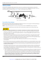
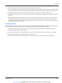
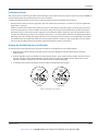
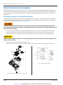
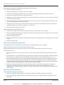
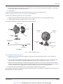
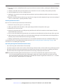
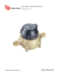
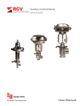
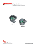
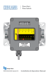
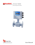
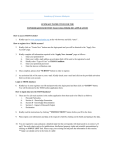
Recordall® Compound Series Meter
Lead-Free Bronze Alloy, Sizes 2", 3", 4" & 6"
NSF/ANSI Standards 61 and 372 Certified
RCS-UM-00076-EN-02 (September 2013)
User Manual
www.mvandc.com | [email protected] | Phone: 877.566.3837 | Fax: 925.407.2903
Recordall® Compound Series Meter, Sizes 2", 3", 4" and 6"
Page ii
September 2013
www.mvandc.com | [email protected] | Phone: 877.566.3837 | Fax: 925.407.2903
User Manual
CONTENTS
SCOPE OF THIS MANUAL . . . . . . . . . . . . . . . . . . . . . . . . . . . . . . . . . . . . . . . . . . . . . . . . . . . . . . . . . . . . . . . . . 5
PRODUCT INFORMATION . . . . . . . . . . . . . . . . . . . . . . . . . . . . . . . . . . . . . . . . . . . . . . . . . . . . . . . . . . . . . . . . 5
Product Description . . . . . . . . . . . . . . . . . . . . . . . . . . . . . . . . . . . . . . . . . . . . . . . . . . . . . . . . . . . . . . . . . 5
Related Literature . . . . . . . . . . . . . . . . . . . . . . . . . . . . . . . . . . . . . . . . . . . . . . . . . . . . . . . . . . . . . . . . . . . 5
Safety Information . . . . . . . . . . . . . . . . . . . . . . . . . . . . . . . . . . . . . . . . . . . . . . . . . . . . . . . . . . . . . . . . . . 5
Unpacking and Inspection . . . . . . . . . . . . . . . . . . . . . . . . . . . . . . . . . . . . . . . . . . . . . . . . . . . . . . . . . . . . . 5
INSTALLATION . . . . . . . . . . . . . . . . . . . . . . . . . . . . . . . . . . . . . . . . . . . . . . . . . . . . . . . . . . . . . . . . . . . . . . . . 6
Preinstallation Considerations . . . . . . . . . . . . . . . . . . . . . . . . . . . . . . . . . . . . . . . . . . . . . . . . . . . . . . . . . . . 6
Installing the Meter . . . . . . . . . . . . . . . . . . . . . . . . . . . . . . . . . . . . . . . . . . . . . . . . . . . . . . . . . . . . . . . . . 7
Adapter Spacers . . . . . . . . . . . . . . . . . . . . . . . . . . . . . . . . . . . . . . . . . . . . . . . . . . . . . . . . . . . . . . . . . 8
Performance Checks . . . . . . . . . . . . . . . . . . . . . . . . . . . . . . . . . . . . . . . . . . . . . . . . . . . . . . . . . . . . . . . . . 9
Reading the Recordall Registers (and Encoder) . . . . . . . . . . . . . . . . . . . . . . . . . . . . . . . . . . . . . . . . . . . . . . . . 9
MAINTENANCE . . . . . . . . . . . . . . . . . . . . . . . . . . . . . . . . . . . . . . . . . . . . . . . . . . . . . . . . . . . . . . . . . . . . . . . 10
Accuracy Testing . . . . . . . . . . . . . . . . . . . . . . . . . . . . . . . . . . . . . . . . . . . . . . . . . . . . . . . . . . . . . . . . . . . 10
Maintenance Equipment . . . . . . . . . . . . . . . . . . . . . . . . . . . . . . . . . . . . . . . . . . . . . . . . . . . . . . . . . . . . . . 10
Preventive Maintenance . . . . . . . . . . . . . . . . . . . . . . . . . . . . . . . . . . . . . . . . . . . . . . . . . . . . . . . . . . . . . . 10
Periodic Inspection . . . . . . . . . . . . . . . . . . . . . . . . . . . . . . . . . . . . . . . . . . . . . . . . . . . . . . . . . . . . . . 11
Cleaning . . . . . . . . . . . . . . . . . . . . . . . . . . . . . . . . . . . . . . . . . . . . . . . . . . . . . . . . . . . . . . . . . . . . . 11
SERVICING PARTS AND ASSEMBLIES . . . . . . . . . . . . . . . . . . . . . . . . . . . . . . . . . . . . . . . . . . . . . . . . . . . . . . . . . 12
Removing the High Flow Turbo Meter Head Assembly . . . . . . . . . . . . . . . . . . . . . . . . . . . . . . . . . . . . . . . . . . . 12
Removing the Turbo Measuring Element Assembly from the Cover Plate . . . . . . . . . . . . . . . . . . . . . . . . . . . . 14
Removing the Magnet Carrier/Top Gear Set . . . . . . . . . . . . . . . . . . . . . . . . . . . . . . . . . . . . . . . . . . . . . . 14
Removing the Straightening Vanes/Nose Cone . . . . . . . . . . . . . . . . . . . . . . . . . . . . . . . . . . . . . . . . . . . . 14
Removing the Calibration Mechanism . . . . . . . . . . . . . . . . . . . . . . . . . . . . . . . . . . . . . . . . . . . . . . . . . . 14
Inspecting the Rotor and Bearings . . . . . . . . . . . . . . . . . . . . . . . . . . . . . . . . . . . . . . . . . . . . . . . . . . . . 16
Removing the Rear Nose Cone . . . . . . . . . . . . . . . . . . . . . . . . . . . . . . . . . . . . . . . . . . . . . . . . . . . . . . . 17
Reinstalling the High Flow Turbo Meter Head Assembly . . . . . . . . . . . . . . . . . . . . . . . . . . . . . . . . . . . . . . . 17
Removing the Low Flow Side . . . . . . . . . . . . . . . . . . . . . . . . . . . . . . . . . . . . . . . . . . . . . . . . . . . . . . . . . . . 18
Servicing the Chamber and Disc . . . . . . . . . . . . . . . . . . . . . . . . . . . . . . . . . . . . . . . . . . . . . . . . . . . . . . 18
Valve Assembly . . . . . . . . . . . . . . . . . . . . . . . . . . . . . . . . . . . . . . . . . . . . . . . . . . . . . . . . . . . . . . . . . . . . 19
Removing the Valve Assembly . . . . . . . . . . . . . . . . . . . . . . . . . . . . . . . . . . . . . . . . . . . . . . . . . . . . . . . 19
Replacing the Valve Assembly . . . . . . . . . . . . . . . . . . . . . . . . . . . . . . . . . . . . . . . . . . . . . . . . . . . . . . . 19
Reinstalling the Cover Assembly . . . . . . . . . . . . . . . . . . . . . . . . . . . . . . . . . . . . . . . . . . . . . . . . . . . . . . . . . 20
SPECIFICATIONS . . . . . . . . . . . . . . . . . . . . . . . . . . . . . . . . . . . . . . . . . . . . . . . . . . . . . . . . . . . . . . . . . . . . . . 20
September 2013
Page iii
www.mvandc.com | [email protected] | Phone: 877.566.3837 | Fax: 925.407.2903
Recordall® Compound Series Meter, Sizes 2", 3", 4" and 6"
Page iv
September 2013
www.mvandc.com | [email protected] | Phone: 877.566.3837 | Fax: 925.407.2903
User Manual
SCOPE OF THIS MANUAL
This manual contains installation, operation and maintenance procedures for the Badger Meter® Recordall® Compound Series
meters with magnetic drives. To ensure efficient operation of the meters, read and understand the instructions in this manual.
Retain the manual in a location where it is readily available.
PRODUCT INFORMATION
Product Description
The Compound Series meters combine two metering technologies in one innovative package. A positive displacement
chamber measures low flow, while a turbine chamber records high flow. The compound meters are available in 2", 3", 4" and
6" sizes.
A spring-loaded valve assembly controls the flow through each of the two measuring elements to provide maximum accuracy
and performance.
The basic components of the compound meter are a housing, Turbo Series head assembly and cover assembly with disc
chamber assembly. The Turbo head assembly includes a Recordall register or encoder for high flow totalization and complete
turbo head components (cage and rotor). The cover assembly includes a Recordall register or encoder for low flow totalization
and a complete chamber assembly.
The output of both measuring elements, the disc and turbo, is transmitted to each Recordall register or encoder by means
of ceramic magnets. The register or encoder is permanently sealed in a controlled environment relative to humidity and
cleanliness, thus assuring longevity of performance.
Related Literature
• The Recordall Compound Series Meters Product Data Sheet contains information on operating principle, meter construction,
materials, tolerances and specifications.
• The Recordall Compound Series Meters Parts List contains illustrations of parts, part numbers, and part descriptions.
Safety Information
The installation of the Recordall Compound Series meter must comply with all applicable federal, state, and local rules,
regulations, and codes.
Failure to read and follow these instructions can lead to misapplication or misuse of the meter, resulting in personal injury and
damage to equipment.
Unpacking and Inspection
To avoid damage in transit, Badger Recordall Compound Series meters are shipped to the customer in special shipping
containers. Upon receipt of shipment, be sure to follow these unpacking and inspection procedures:
NNOTE: If damage to a shipping container is evident upon receipt of a meter, request that a representative of the carrier be
present when the meter is unpacked.
a. Carefully open the shipping container, following any instructions that may be marked on the container. Remove all
cushioning material surrounding the meter and carefully lift the meter from the container. Keep the container and
all packing material for possible use in reshipment or storage.
b. Visually inspect the meter and applicable accessory devices for any signs of damage such as scratches, loose or
broken parts or other physical damage that may have occurred during shipment.
NNOTE: If damage is found, request an inspection by carrier’s agent within 48 hours of delivery. Then file a claim with the
carrier. A claim for equipment damaged in transit is the responsibility of the customer.
September 2013
Page 5
www.mvandc.com | [email protected] | Phone: 877.566.3837 | Fax: 925.407.2903
Recordall® Compound Series Meter, Sizes 2", 3", 4" and 6"
INSTALLATION
Procedures for installing Recordall Compound Series meters are essentially the same for all meter sizes. Any special
instructions required for the installation or connection of accessory devices such as AMR/AMI technologies or strainers is
provided in the literature for those devices. Figure 1 shows a recommended meter installation.
By-Pass
(Permanent or
Temporary)
Valve
(Open)
Minimum of Five
Diameters of
Straight Pipe
Upstream
Downstream
Badger Plate
Strainer and
Compound Meter
Coupling
Adaptor
Shut-Off
Valve
Figure 1: Recommended meter installation
Preinstallation Considerations
Before proceeding any further with the installation, first read the instructions in the paragraphs immediately following to
become familiar with the requirements and procedures involved.
NNOTE: The Recordall Compound Series meters are designed for operation in HORIZONTAL piping arrangements.
• Be sure that the meter flow range and size of the meter coincide with the intended service and demand for water.
THE LIFE OF THE COMPOUND METER WILL BE CURTAILED IF OPERATED AT FLOW RATES HIGHER THAN SPECIFIED.
• The meters are designed for use in cold water service (up to 120° F or 27° C) within the applicable flow requirements
for compound meters. For use with water at higher temperatures, consult your Badger Meter representative or nearest
Badger Meter regional sales office.
• If solid material is present in the water to be metered, a strainer must be installed in the service piping upstream of the
meter. The strainer, in addition to protecting the meter from debris in the line, minimizes the effect of velocity profile
distortions or turbulence caused by changes in pipe direction or valving resulting in more accurate registration. Contact
your Badger Meter representative for information on Recordall Plate Strainers.
• Avoid locating the meter in close quarters. Allow sufficient space to permit access for meter reading, testing,
and maintenance.
• Because of the need to test large meters periodically to verify their performance, it is recommended that a bypass system
be incorporated into the piping arrangement. This will also provide a means of performing periodic cleanout and routine
maintenance without interrupting service to the customer. A test port is incorporated in the meter housing and can be
used for field accuracy testing.
• The Recordall Compound Series meter is accuracy and pressure tested prior to shipment, therefore no field adjustments
are required. As turbine performance is directly related to the flow conditions of the water stream entering the meter,
upstream fittings and piping changes can adversely affect flow registration. For valid registration and proper performance,
consider the following installation considerations:
◊ When installing the meter with a Badger Meter Plate Strainer, a minimum of 5 pipe diameters of straight, unobstructed
pipe is required upstream of the meter. (A minimum of 10 pipe diameters of straight unobstructed pipe is required
upstream of a meter installed without a plate strainer. The deletion of a strainer, however, is not recommended.) This
allows for dampening of velocity profile distortions caused by items such as elbows, pumps and dirt traps upstream
of the meter. Where spiral flows are created by three dimensional elbows or rotary pumps, use additional distance
to dampen the effect. If a basket or Y-type strainer is used, place it 5 to 10 pipe diameters upstream of the meter to
dampen velocity profile distortions created by this design.
Page 6
September 2013
www.mvandc.com | [email protected] | Phone: 877.566.3837 | Fax: 925.407.2903
User Manual
◊ Do not install check valves or pressure reducing devices upstream of the meter.
◊ Valves immediately upstream of the meter should only be fully-open gate valves. Butterfly valves are acceptable if they
are 5 pipe diameters or more upstream from the meter. Downstream, fully open gate or butterfly valves can be used.
◊ Unweighted check valves should not be located closer than 3 pipe diameters downstream of the meter.
◊ Externally weighted check valves and pressure reducing devices should not be located closer than 5 pipe diameters of
the meter.
◊ When installing a compound meter and plate strainer of a size smaller than the pipe installation, to reduce the effect
of jetting caused by the increase in flow velocity, a minimum of 5 pipe diameters of pipe equal in size to the meter, is
required upstream of the meter. Additional length is required if a sharp contraction or an eccentric reducer, rather than
a concentric, tapered reducer is used.
Installing the Meter
Overall dimensions and laying lengths of each meter size are listed in the Recordall Compound Series Meter Product Data Sheet.
Review the dimensional requirements, choose an installation point in the piping, and proceed as follows:
1. Measure precisely the overall length of the meter with gaskets attached to the inlet and outlet flange connections.
2. Provide proper gap length in service piping.
3. Install meter in the pipeline so that the flow arrow on the meter housing points in the same direction as water flow.
4. With meter and gaskets in place, tighten flange connection bolts.
5. To relieve possible strain on the piping, position a meter support under the meter housing where appropriate.
September 2013
Page 7
www.mvandc.com | [email protected] | Phone: 877.566.3837 | Fax: 925.407.2903
Recordall® Compound Series Meter, Sizes 2", 3", 4" and 6"
Adapter Spacers
The 2" and 4" Compound Series meters are supplied in 15-1/4" and 20" lay lengths respectively. If you have an existing
compound meter with a lay length of 17" for the 2" size or 24" for the 4" size, a Flange Adapter Kit is available for each to
accommodate the difference. Mount the Flange Adapter to the outlet side of the meter.
Figure 2: 2" adapter
Figure 3: 2" adapter with a 2" elliptical meter
Figure 4: 2" adapter with a 2" round meter
Figure 5: 4" adapter
Figure 6: 4" with a 4" meter
Description
Part Number
2" Elliptical Flange Adapter Kit
64186-001
2" Round Flange Adapter Kit
64186-002
4" Flange Adapter Kit
64186-003
COMPOUND METERS MUST OPERATE IN A COMPLETELY FILLED LINE AT ALL TIMES. THE DOWNSTREAM PIPING MUST
ALWAYS BE ARRANGED TO PROVIDE SUFFICIENT BACK PRESSURE TO MAINTAIN A FULL LINE AT THE METER. BY
ELIMINATING AIR IN THE LINE, AS WELL AS SUDDEN FLOW SURGES, INACCURATE REGISTRATION AND DAMAGE TO THE
TURBINE MECHANISM CAN BE AVOIDED.
Page 8
September 2013
www.mvandc.com | [email protected] | Phone: 877.566.3837 | Fax: 925.407.2903
User Manual
Performance Checks
Any valves or devices controlling the flow of water through a compound meter must always be opened and closed SLOWLY to
prevent shock loads that may damage the meter’s rotor assembly.
Complete the following checks to ensure that a compound meter is properly installed and operational:
• Slowly open the upstream valve to apply water pressure to the meter and check to see if there are any leaks. Tighten the
flange bolts as required.
• Perform a functional test of the meter. Slowly open valve on downstream side of the meter to evacuate any air that may
have been trapped in the service line. When air has been eliminated, increase demand flow rate by further opening the
downstream valve or valves. Observe the register for correct direction of flow. Continue to open the demand side valves
to a flow rate sufficient to open the valve assembly in the meter—a procedure which will start water flowing through the
turbo high-side rotor. The high flow pointer will now move in the proper direction. Now open all applicable service valves.
• Check the flow rate to verify that the flow does not exceed the maximum continuous duty specification. The rate of flow
can be quickly checked by timing the quantity registered through the meter in one minute.
Reading the Recordall Registers (and Encoder)
To determine the total reading for meter, the totals for both low and high flow must be added together.
1. Determine the low flow total by reading the registere/encoder identified as low flow. Read only the moveable
number wheels.
2. From the high flow register, read both the number wheels and the sweep hand. Read the number wheels first. Read
only the moveable number wheels. Note the position of the sweep hand, round the number down to the nearest
increment. Add the reading from the number wheel and the sweep hand together.
3. To determine the complete total flow, add the low flow and high flow totals together.
9
0
Recordall
0
90 Recordall ® 10
1
®
Compound
400
Compound
8
Badger Meter
2
64063-017
80
20
Badger Meter
64063-002
2"/3"
Gallons
7
6
Low Flow
Total Flow=High + Low
®
3
4
3"
Gallons
70
60
High Flow
®
30
40
5
50
Low Flow
High Flow
Figure 7: Reading the register example
September 2013
Page 9
www.mvandc.com | [email protected] | Phone: 877.566.3837 | Fax: 925.407.2903
Recordall® Compound Series Meter, Sizes 2", 3", 4" and 6"
MAINTENANCE
This section is limited to information pertaining to the general maintenance of Badger Meter Recordall Compound Series
meters. An exploded view of the meter, along with part numbers and descriptions, are provided in the Recordall Compound
Series Meters Parts List.
Accuracy Testing
The Compound Series meter can be tested for accuracy with a test meter or a test tank of known volume. A test plug is
provided on the meter. The low flow register is for recording the amount of water passing through the disc, or low flow side
of the meter. The high flow register is for recording the amount of water passing through the turbo, or high flow side of
the meter.
When testing at flow rates below the meter’s cross-over point, only the low flow test hand will move. Record the initial reading
(low flow odometer and low flow test circle). To determine the amount of water that has passed through the meter during
test, take the new reading from the low flow test circle. If more than one revolution of the test circle, take a new reading from
both the low flow odometer and the low flow test circle. The difference between the initial and final reading is then compared
to that recorded by the test meter or test tank.
When testing flow rates at or above the meter’s crossover point, the high flow and low flow register test hands will move.
This is because both sides of the meter, disc and turbo, operate simultaneously at these flow rates. The disc side of the meter
operates at all flow rates to keep the chamber free of debris that might enter the meter. Record the initial readings (high flow
odometer and high flow test circle, low flow odometer and low flow test circle). If less than one revolution of the high flow
test circle, record both the new high flow and low flow test circle readings. The amount of flow recorded by the high flow and
low flow test circles during test must be added together to determine the total flow through the meter. Compare this to that
recorded by the test meter or test tank.
If more than one revolution of the high flow test circle occurs, take new readings from the low flow odometer, high flow and
low flow test circles and add all complete high flow test circle revolutions to this. Once again, the amount of flow recorded by
the high flow and low flow test circles must be added together and combined to determine the total flow through the meter. This
is then compared to that recorded by the test meter or test tank.
A simplified alternative to recording the initial and final odometer readings on the high flow and low flow odometers, is to
record the number of complete revolutions of the test hand on the high flow and/or low flow test circles during test. This is
then added to the difference between the initial and final position of the test hands on the test circles to determine the total flow
through the meter.
For correct testing procedures, and test volumes based upon meter flow rates, please refer to AWWA M-6 Manual. Starting the
test when the register test circle hands are on zero and operating the meters through complete revolution of the test circles
are desirable operating procedures to follow.
THE TEST HANDS OPERATE INDEPENDENTLY OF ONE ANOTHER. FOR EXAMPLE, DURING METER OPERATION AT FLOWS
BELOW CROSSOVER, THE LOW FLOW TEST HAND WILL REVOLVE WHILE THE HIGH FLOW TEST HAND IS STATIONARY,
ALLOWING HIGHER READINGS ON THE LOW FLOW ODOMETER ONLY.
Maintenance Equipment
The tools and equipment recommended for use in servicing and maintaining of Recordall Compound Series meters consist of
the usual complement of hand tools used by plumbers and mechanics.
Preventive Maintenance
The purpose of preventive maintenance is to ensure efficient operation and long life of the meter by detecting and correcting
any defect that might damage the meter or cause it to fail. Preventive maintenance consists of periodic inspection, accuracy
testing, and cleaning procedures.
Page 10
September 2013
www.mvandc.com | [email protected] | Phone: 877.566.3837 | Fax: 925.407.2903
User Manual
Periodic Inspection
• Visually inspect the meter for missing hardware, loose screws, broken or scratched register lenses or any other signs of
wear or deterioration.
• Verify that the meter is operating at the proper flow rate and pressure. A loss in pressure, coupled with a decrease in flow
rate, may indicate that the screen in the upstream pipeline—or the meter itself—is clogged with foreign material and
needs cleaning.
Cleaning
• Clean all dirt, grease, moisture or other foreign material from the exterior of the meter. After cleaning, rinse thoroughly
with water.
• In the event that system pressure has been reduced and the upstream filter or meter is clogged, the foreign material
must be flushed out. To flush the screen, open the cleanout plug and purge the foreign material with fresh water from
the service line. If cleaning the screen does not restore system pressure, the compound meter also should be flushed by
purging with fresh service water through the cleanout plugs located on the housing.
September 2013
Page 11
www.mvandc.com | [email protected] | Phone: 877.566.3837 | Fax: 925.407.2903
Recordall® Compound Series Meter, Sizes 2", 3", 4" and 6"
SERVICING PARTS AND ASSEMBLIES
When the performance of a compound meter indicates a need for servicing, refer to the following instructions pertaining to
removal, inspection and installation of service parts and assemblies. Also see the Recordall Compound Series Meter Parts List for
part numbers of replaceable components and correct ordering information. If satisfactory repair cannot be made, contact
Badger Meter.
Removing the High Flow Turbo Meter Head Assembly
A typical installation would be equipped with drain and piping valves. To inspect or replace components of the High Flow
Turbo Head Assembly, close the upstream and downstream valves. However, if the installation does not have a drain valve,
proceed as follows to relieve pressure. See Figure 8 on page 12.
UPSTREAM AND DOWNSTREAM VALVES MUST BE CLOSED BEFORE ATTEMPTING TO REMOVE METER HEAD FROM
HOUSING. FAILURE TO DO SO CAN LEAD TO THE HEAD BEING "EJECTED" FROM HOUSING, CAUSING PERSONAL INJURY
AND/OR PROPERTY DAMAGE!
1. Loosen each of the High Flow Turbo Head Assembly bolts about 1-1/2 turns. Do not completely remove the bolts.
2. If the O-ring between the High Flow Turbo Head Assembly and the housing is secure and not leaking, pry the
Measuring Element Assembly loose by inserting a screwdriver blade where the head and housing join together.
BE SURE THAT ANY WATER COMING OUT OF THE METER HEAD DOES NOT SPRAY ONTO ELECTRICAL EQUIPMENT AND
CREATE A SHOCK HAZARD.
3. Allow the meter to drain and relieve internal pressure.
4. When pressure is relieved, remove the head bolts. Lift the Turbo measuring element assembly from the housing.
High Flow
Register
Low Flow
Register
High Flow Turbo
Meter Head
Assembly
Cage Seal
Cover
Assembly
O-Ring
Figure 9: Chamber and disc assembly
Housing
Drain Plug
Figure 8: Removing the high flow turbo meter head assembly
Page 12
September 2013
www.mvandc.com | [email protected] | Phone: 877.566.3837 | Fax: 925.407.2903
User Manual
6"
Calibration shaft seal plug
O-ring
Cover plate
Hold down strap
Transmission shaft gear
Protection tube
Nose cone setscrew
Cage insert
Calibration shaft lock screw
Calibration shaft
Head O-ring
Magnet carrier
Calibration linkage
Nose cone setscrew
Nose cone/straightening
vane assembly (2)
Transmission shaft
Rotor
bottom bearing
Calibration ring (rear)
Calibration ring (front)
Cage setscrew (1)
Cage seal
2", 3" and 4"
Figure 10: High flow turbo measuring element assemblies
September 2013
Page 13
www.mvandc.com | [email protected] | Phone: 877.566.3837 | Fax: 925.407.2903
Recordall® Compound Series Meter, Sizes 2", 3", 4" and 6"
Removing the Turbo Measuring Element Assembly from the Cover Plate
1. Remove the O-ring and cage seal.
2. Check for damage and clean or replace prior to reassembly.
3. To remove the measuring element from the cover, remove the calibration shaft seal plug and the lock screw.
4. Place the cover register-side down on a table or flat surface.
5. Lightly tap or press the calibration shaft from the wet side out of the bore in the cover (2", 3" and 4" only). Do not strike
or bend the calibration linkage.
6. The measuring element insert can be removed from the cover plate for service or replacement by removing the cage
set screws (quantity of one, except for the 6" size.)
7. Holding the cover plate in one hand, rotate the thermoplastic element counter-clockwise until the bayonet-like tabs
are aligned with open areas of the cover plate (2", 3" and 4" only).
8. Remove the element from the cover plate.
Removing the Magnet Carrier/Top Gear Set
1. To remove the magnet carrier from the measuring element insert, lift it off the stainless steel pin.
2. Check the condition of the magnet and gear on the magnet carrier for damage or wear. If significant wear or damage is
present, replace the magnet carrier.
3. Remove the hold-down strap.
4. Check the condition of the transmission shaft gear for damage or wear. If significant wear or damage is present, replace
the gear.
5. Lift the gear off the shaft.
Removing the Straightening Vanes/Nose Cone
The straightening vanes are an integral part of the upstream and downstream nose cone assemblies.
To gain access to them, remove the measuring element from the cover.
Removing the upstream nose cone provides access to the rotor, calibration ring and the transmission assembly.
To remove the nose cone:
1. Unscrew the upstream nose cone setscrew. For 2", 3" and 4" meters, slide the calibration linkage into the cage insert
stop.
2. Take hold of the nose cone/straightening vanes and turn them clockwise, thereby disengaging the calibration linkage
from the tab on the calibration ring and unlocking the bayonets of the nose cones from the cage (see Figure 12).
3. If the tab of the calibration ring has not disengaged the linkage, rotate the ring carefully by pushing the struts at the
interior of the element (between the straightening vanes and the rotor). Pull the nose cone assembly out from the
measuring element insert. For 6" meters, remove the transmission gear by lifting it off the shaft, noting the alignment
of the D-shaped bore with the flat on the shaft (required to align for assembly).
4. Remove the retaining ring that holds down the calibration drive plate, located under magnet carrier magnet (see
Figure 8). Remove drive plate. Rotate calibration ring until pin clears slot of cage. Take hold of the nose cone/
straightening vanes and turn clockwise. Pull the nose cone assembly out from the measuring element insert. Remove
rotor assembly.
Removing the Calibration Mechanism
To disassemble the calibration ring assembly:
1. Remove the calibration shaft seal plug and unscrew the calibration shaft lock screw from the cover plate.
2. Remove the calibration shaft thrust washer and calibration shaft. Press the calibration shaft out of the cover plate
from below.
Page 14
September 2013
www.mvandc.com | [email protected] | Phone: 877.566.3837 | Fax: 925.407.2903
User Manual
3. If a leak exists at this point in the disassembly of the meter, remove the calibration shaft O-ring. Before reinserting the
O-ring, apply a light coat of silicon grease to it.
4. Clean all parts.
To gain access to the calibration ring, the straightening vane/nose cone must be removed. See
“Removing the Magnet Carrier/Top Gear Set” on page 14 for instructions.
To remove the calibration ring from the nose cone assembly:
1. Align the ring slots with the bayonets of the nose cone assembly (located on inner ring of calibration ring).
2. Carefully lift the calibration ring from the nose cone assembly.
To reinstall the calibration mechanism, follow this procedure in reverse.
CALIBRATION RING
PIN
ARROW TIP
CAGE
INSERT
PIN OF
CALIBRATION
RING
CAGE INSERT
(TOP VIEW)
NOSE
CONE
CALIBRATION
LINKAGE
SMALL HOLE WITH
CHAMFER UP
TRANSMISSION
GEAR
TOP SIDE
RETAINING RING
INTO CAGE
THIS END
LARGE HOLE WITH
CHAMFER DOWN
2", 3" and 4"
CALIBRATION DRIVE
PLATE
6"
Figure 11: Calibration ring/linkage assemblies
Reassembling the Calibration Mechanism
1. Align the pin on the perimeter of the calibration ring with the arrow tip located on the nose cone assembly (see
Figure 11 on page 15).
2. For 2", 3" and 4" sizes, install the calibration linkage into the cage with the larger hole to engage the calibration ring
tab, with the side of chamfered edge of the hole towards the nose cone assembly (see Figure 11 on page 15).
3. With the calibration linkage fully inserted to the cage stop, install the nose cone onto the cage and rotate it counterclockwise to engage the pin of the ring to the calibration linkage. The hole of the calibration linkage has to be aligned
onto the calibration shaft, engaging it fully so that the calibration ring cannot vibrate during operation.
4. Tighten the calibration shaft lock screw to securely hold the calibration ring in position.
After servicing or replacing the calibration mechanism, check the accuracy and calibration according to the instructions in the
Recordall Turbo Series Meter User Manual.
September 2013
Page 15
www.mvandc.com | [email protected] | Phone: 877.566.3837 | Fax: 925.407.2903
Recordall® Compound Series Meter, Sizes 2", 3", 4" and 6"
Inspecting the Rotor and Bearings
To inspect the rotor, remove the nose cone assembly from the measuring element insert as described in
"Removing the Magnet Carrier/Top Gear Set" on page 14.
Check the rotor worm and blades for signs of damage and wear. Also inspect the bearing bushings in the front and rear shaft.
If damage or wear has occurred, replace the part (see Figure 12). If water deposits are found, remove any mineral deposits
from the rotor blade surfaces, cage insert interior disc, and nose cone vanes and mating surfaces.
Inspect the rotor bearing pins in the straightening vane and nose cone assembly for signs of damage and wear (see
Figure 12). The spherical end of the bearing pin must not show any drag lines and/or wear.
ROTOR
BEARINGS (2)
ROTOR
WORM
NOSE CONE
ASSEMBLY
(2)
BEARING
PIN
Figure 12: Rotor and nose cone assembly (2", 3", 4" and 6" turbo head assemblies)
NNOTE: Only highly-polished bearing pin ends provide a minimum of friction and optimal meter performance. Bearing
pins are an integral part of the straightening vane and nose cone assembly. Wear or damage would require the
replacement of this component.
Reassembling the Rotor and Bearings
1. Install the rear nose cone to the cage. See "Removing the Magnet Carrier/Top Gear Set" on page 14.
2. Place the rotor assembly with the worm gear side leading through the cage.
3. Place the rotor assembly on the rear rotor bearing pin, while tipping the assembly back so that the opening is up. See
“Removing the Calibration Mechanism” on page 14 for instructions on assembling the calibration rings with the
nose cone assembly.
4. Insert the front nose cone assembly partially onto the cage insert, engaging the bearing pin with the front bearing of
the rotor.
5. Tilt the measuring element insert assembly forth and back to see that the rotor now engages the bearing pins on the
straightening vane/nose cones and is free to rotate and slide.
DO NOT FORCE THE NOSE CONE ASSEMBLY INTO THE CAGE INSERT. BE SURE THAT THE ROTOR ENGAGES BOTH THE
FRONT AND REAR ROTOR BEARING PINS PRIOR TO PRESSING THE NOSE CONE ASSEMBLY FULLY INTO THE CAGE
INSERT.
Page 16
September 2013
www.mvandc.com | [email protected] | Phone: 877.566.3837 | Fax: 925.407.2903
User Manual
6. Press the nose cone assembly fully into the cage insert and turn it counter-clockwise, catching the calibration linkage
in the slot.
7. Check to see that the rotor spins freely. If it does not, remove the nose cone assembly and repeat the procedure.
8. Install and tighten the nose cone assembly setscrew.
9. Holding the cover plate in one hand, align the thermoplastic cage bayonet-like tabs with the slots in the cover plate
(2", 3" and 4" only).
10.Rotate the element clockwise until the cage setscrew hole is aligned. Install and tighten the cage setscrews (quantity of
1 for 2", 3" and 4" meters, a quantity 4 for the 6" meter).
Removing the Rear Nose Cone
Rear nose cone removal requires transmission shaft removal.
1. Remove the strap over the gear (2", 3", and 4" only).
2. Lift the gear off the shaft. The shaft has a flat spot that aligns with the D-shaped bore in the gear.
3. Remove the nose cone set screw.
4. Remove the protection tube by carefully pressing (with flat surface of blade screwdriver) on the bottom of the tube
located inside the rear nose cone.
5. Press to release the detent lock, approximately 1/4" vertical travel, then lift the tube out from the top of the cage insert.
6. Lift the transmission shaft assembly up and out of the bottom bearing, then slide shaft downward and diagonally out
(towards you) to remove it from the nose cone/cage assembly.
7. Holding cage firmly with one hand, rotate the nose cone clockwise with other hand, then carefully lift it off the cage.
To reinstall the rear nose cone, follow this procedure in reverse. See “Inspecting the Rotor and Bearings” on page 16 for
instructions on reassembling the components.
Reinstalling the High Flow Turbo Meter Head Assembly
• Use a new O-ring after each teardown and reassembly.
• To provide a tight seal, make sure the surfaces of the housing and meter head are clean and free of any old O-ring material.
• Be careful not to force the measuring element insert into the meter housing. If you experience any binding, do not force
the element into the housing. Remove the element from the housing and properly reinsert the unit.
NNOTE: Head bolts should be tightened similar to that on car tire. First insert the bolts and snug-fit each. Then, using a
crisscross pattern, tighten the bolts down. Following this pattern, the meter head will not turn and the rotor will
remain perpendicular to the flow, eliminating any potential flow distortion. Tighten the head bolts to 10…11 ft-lb for
the 2" size, and 35…40 ft-lb for the 3", 4" and 6" sizes.
September 2013
Page 17
www.mvandc.com | [email protected] | Phone: 877.566.3837 | Fax: 925.407.2903
Recordall® Compound Series Meter, Sizes 2", 3", 4" and 6"
Removing the Low Flow Side
Follow same removal steps for the cover as listed in “Removing the High Flow Turbo Meter Head Assembly” on page 12.
High Flow
Register
Turbo Head
Assembly
Low Flow
Register
Chamber
Assembly
Bottom Plate
Bypass Seal
Cover Seal
Figure 13: Removing the low flow side
Servicing the Chamber and Disc
1. Remove the screws holding the bottom plate on the cover assembly.
2. Remove the bottom plate.
3. Remove the chamber retaining strap.
4. Lift out the chamber and disc assembly.
5. Inspect the chamber and parts (see Figure 9) for visible signs of wear. The thrust roller and dovetail insert should be
replaced if worn. Replace the chamber if wear is evident on disc spindle where it contacts the crossbar magnet drive or
the balls or if the disc plate is worn by foreign material. If water deposits are found, remove any mineral deposits from
the disc and chamber interior surfaces. Before replacing the chamber in the meter head, make certain that the area
surrounding the magnet in the meter head is clean.
Page 18
September 2013
www.mvandc.com | [email protected] | Phone: 877.566.3837 | Fax: 925.407.2903
User Manual
Valve Assembly
Removing the Valve Assembly
With the cover assembly removed, the valve assembly is exposed for service.
1. Remove the lock pawl (see Figure 14).
2. Turn the valve assembly counter-clockwise to unscrew it from the housing.
3. Lift the valve assembly out of the housing.
Replacing the Valve Assembly
If any portion of the valve assembly requires replacement, we recommend replacing the entire valve assembly.
1. Drop in the new assembly.
2. Turn the assembly clockwise to thread it into the housing.
3. Drop the lock pawl back into position to lock in the assembly.
NNOTE: The 4" and 6" assemblies cannot be disassembled and must be completely replaced. Complete replacement of 2" and
3" is also recommended as noted, but the seal can be replaced with a special tool. Please contact Badger Meter for
further details.
High Flow
Register
Turbo Head
Assembly
Low Flow
Register
Cover
Assembly
Lock Pawl
Valve
Assembly
Figure 14: Valve assembly
September 2013
Page 19
www.mvandc.com | [email protected] | Phone: 877.566.3837 | Fax: 925.407.2903
Reinstalling the Cover Assembly
Badger Meter recommends that a new O-ring be used after each teardown and reassembly of the cover assembly. To assure
a tight seal, make sure O-ring is positioned correctly on the housing and that the O-ring and cover assembly are clean and
free of dirt or residual traces of old O-ring material. If necessary, use silicone grease to help retain the O-ring and to serve as a
lubricant in reassembling it to the housing.
Cover bolts should be tightened in a crisscross pattern similar to Turbo head bolts. Torque 2" and 3" cover assembly bolts to
16…18 ft-lb. Torque the bolts for the 4" and 6" cover assemblies to 35…40 ft-lb.
SPECIFICATIONS
Compound Series Model
Meter Flanges, Class 150
2" (50 mm)
3" (80 mm)
4" (100 mm)
6" (150 mm)
2" elliptical or round
3" round
4" round
6" round
(50 mm)
(80 mm)
(100 mm)
(150 mm)
Typical Operating Range
0.5…200 gpm
0.5…450 gpm
0.75…1000 gpm
0.75…2000 gpm
(100% ± 1.5%)
(0.1…45 m3/h)
(0.1…102 m3/h)
(0.17…227 m3/h)
(0.17…454.4 m3/h)
Low Flow Registration
(97% minimum)
0.25 gpm (0.06 m3/h)
0.25 gpm (0.06 m3/h)
0.375 gpm (0.09 m3/h)
0.375 gpm (0.09 m3/h)
Maximum Continuous Flow
170 gpm (38.3 m3/h)
400 gpm (90.3 m3/h)
800 gpm (181.6 m3/h)
1500 gpm (340.5 m3/h)
Pressure Loss at Maximum
Continuous Flow
5.4 psi at 170 gpm
6.0 psi at 400 gpm
11.0 psi at 800 gpm
9.3 psi at 1500 gpm
(0.38 bar at 38.3 m3/h)
(0.41 bar at 90.3 m3/h)
(0.75 bar at 181.6 m3/h)
(0.64 bar at 340.5 m3/h)
Crossover Flow Rate, Typical
Pressure Loss at Crossover
Minimum Crossover Accuracy
12 gpm
12 gpm
20 gpm
30 gpm
3.5 psi (0.24 bar)
4.0 psi (0.28 bar)
4.0 psi (0.28 bar)
5.0 psi (0.35 bar)
97%
97%
97%
95%
Maximum Operating Pressure
150 psi (10 bar)
Maximum Operating
Temperature
105° F (41° C)
Test Plug
1-1/2"
2"
Materials
Meter Housing & Cover
Lead-free bronze alloy
Turbo Cast Head
Lead-free bronze alloy
Nose Cone & Straightening Vanes
Thermoplastic
Rotor
Thermoplastic
Rotor Radial Bearings
Lubricated thermoplastic
Rotor Thrust Bearing
Sapphire jewels
Rotor Bearing Pivots
Passivated 316 stainless steel
Calibration Mechanism
Stainless steel & thermoplastic
Measuring Chamber & Disc
Thermoplastic
High Flow Valve
Stainless steel & thermoplastic
Magnets
Ceramic
Register Lens
Glass
Register Housing & Cover
Thermoplastic or bronze
Trim
Stainless steel
Drain Plug (3/4")
Stainless steel or lead-free bronze alloy
Test Plug
Stainless steel or lead-free bronze alloy
ORION, Recordall, and RTR are registered trademarks of Badger Meter, Inc. Other trademarks appearing in this document are the property of their respective entities. Due to
continuous research, product improvements and enhancements, Badger Meter reserves the right to change product or system specifications without notice, except to the
extent an outstanding contractual obligation exists. © 2013 Badger Meter, Inc. All rights reserved.
www.badgermeter.com
The Americas | Badger Meter | 4545 West Brown Deer Rd | PO Box 245036 | Milwaukee, WI 53224-9536 | 800-876-3837 | 414-355-0400
México | Badger Meter de las Americas, S.A. de C.V. | Pedro Luis Ogazón N°32 | Esq. Angelina N°24 | Colonia Guadalupe Inn | CP 01050 | México, DF | México | +52-55-5662-0882
Europe, Middle East and Africa | Badger Meter Europa GmbH | Nurtinger Str 76 | 72639 Neuffen | Germany | +49-7025-9208-0
Czech Republic | Badger Meter Czech Republic s.r.o. | Maříkova 2082/26 | 621 00 Brno, Czech Republic | +420-5-41420411
Slovakia | Badger Meter Slovakia s.r.o. | Racianska 109/B | 831 02 Bratislava, Slovakia | +421-2-44 63 83 01
Asia Pacific | Badger Meter | 80 Marine Parade Rd | 21-04 Parkway Parade | Singapore 449269 | +65-63464836
Legacy Document Number: RCS-IOM-1
China | Badger Meter | 7-1202 | 99 Hangzhong Road | Minhang District | Shanghai | China 201101 | +86-21-5763 5412
www.mvandc.com | [email protected] | Phone: 877.566.3837 | Fax: 925.407.2903