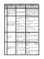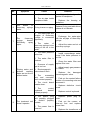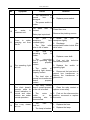
1
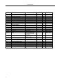
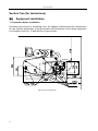
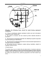
Ritter® Superior
Chair-mounted Dental Unit
Instruction Manual
User Manual
Service Manual
J1181, V03.00.01
J1181, V03.00.01
z
Thank you for choosing our product.
z
It is designed for users to safely and effectively use this equipment. Please
carefully read the product instruction manual before installation and
debugging as well as operation and maintenance, and properly keep it for
future use.
z
Properly keep the product quality maintenance card, product instruction
manual as well as installation and maintenance accessories provided with
product.
z
Please strictly follow the operation instruction when using and properly
maintain it.
z
Any problems arise during using, please contact with local distributor or our
company, and we will provide you with excellent service and help.
z
Commitment: when handling failure, if necessary, we commit to provide users
with necessary and more specific technical data.
1
J1181, V03.00.01
Number
1
1.1
1.2
1.2.1
1.2.2
1.2.3
1.2.4
1.2.5
1.2.6
1.2.7
1.2.8
1.2.8.1
1.2.8.2
1.2.8.3
1.2.8.4
1.2.8.5
1.2.8.6
1.2.8.7
Name
Chair Unit Part
Dental Chair Part(main body)
Light Arm Part
Light Arm(main body)
Bowl Rinse Spout
Cup Fill spout
Spittoon Cover
Protective cushion cover
Water Bottle
Operation manual
Plastic Membrane
Saliva ejector tip
Suction tip
Suction Fitter
Syringe tip
Connector
Valve
Fuse
1.2.8.8
Pipe
1.3
1.3.1
1.3.2
1.3.3
1.4
1.4.1
1.4.2
1.4.3
1.4.4
Operation Light part
Operation Light (main body)
Bulb
Tools
Dentist Operating Stool
Seat Cushion
Backrest
Gas Spring
Furcation Truckle
2
Order Number
JPC8-G1/2”
G1/2”
RF1-20:(ø5X20, 0.2A
1A 2A 3.15A 5A 10A
glass tube)
ø8X1(Blue
Black),L=1.5m
50W 12V halogen bulb
Quantity
1
1
1
1
1
1
1
1
1
1
1
1
Unit
Sets
Sets
Sets
Sets
p.c.
p.c.
p.c.
p.c.
p.c.
p.c.
p.c.
p.c.
Remark
1
2
1
2
p.c.
p.c.
p.c.
p.c.
Spare Part
Spare Part
Spare Part
Spare Part
Spare Part
Spare Part
Spare Part
1
p.c.
Spare Part
1
1
1
1
1
1
1
1
1
Sets
Sets
p.c.
p.c.
Sets
p.c.
p.c.
p.c.
p.c.
Spare Part
J1181, V03.00.01
Contents
I. General ..................................................................................................................................................... 5 II. Transportation and storage ....................................................................................................................... 9 III. Environmental safety................................................................................................................................ 9 1. Disposal of packing material ........................................................................................................ 9 2. Disposal of equipment ................................................................................................................... 9 Section one (For end user) ................................................................................................................................. 11 IV. Illustrations............................................................................................................................................. 11 V. Profile..................................................................................................................................................... 12 VI. Structure of complete machine............................................................................................................... 12 VII. Working Conditions ............................................................................................................................... 13 VIII. Main technical parameters...................................................................................................................... 13 IX. External dimension of equipment........................................................................................................... 14 X. Operation................................................................................................................................................ 15 1. Invocate power switch ................................................................................................................. 15 2. Heating of rinsing water .............................................................................................................. 15 3. Water supply of rinsing................................................................................................................ 16 4. Water supply of spittoon washing ............................................................................................ 16 5. Installation of handpiece ............................................................................................................. 16 6. Handpiece operation..................................................................................................................... 16 7. Air and water pressure adjustment of handpiece................................................................. 17 8. Installation of three-way syringe ............................................................................................... 17 9. Three-way syringe operation...................................................................................................... 17 10. Saliva ejector and high vacuum suction ............................................................................. 18 11. Water bottle system .................................................................................................................. 18 12. Operation of electric chair ...................................................................................................... 19 13. Operation of preset position of electric chair .................................................................... 19 14. Reset button ............................................................................................................................... 19 15. Head rest...................................................................................................................................... 19 16. Hand rest ..................................................................................................................................... 20 17. Dentist Stool ............................................................................................................................... 20 XI. Cleaning and sterilization....................................................................................................................... 20 1. Handpiece........................................................................................................................................ 20 2. Other instruments ......................................................................................................................... 20 3. Exterior accessories..................................................................................................................... 20 Section Two (for technicians)............................................................................................................................. 22 XII. Equipment installation............................................................................................................................ 22 1. Preparation before installation................................................................................................................ 22 2. Pipeline layout........................................................................................................................................ 23 3. Installation step ...................................................................................................................................... 24 XIII. Function debugging................................................................................................................................ 26 1. Adjustment of filter relief valve.................................................................................................. 26 2. Main controlling board................................................................................................................. 26 3. Setup of the automatic control .................................................................................................. 28 4. Setting of instrument arm ........................................................................................................... 29 XIV. Maintenance ........................................................................................................................................... 29 1. Handpiece........................................................................................................................................ 29 2. Water filter ....................................................................................................................................... 29 3. Relief valve of air filtration .......................................................................................................... 30 3
J1181, V03.00.01
4. Saliva ejector and suction ........................................................................................................... 30 5. High vacuum filter screen r......................................................................................................... 30 6. Filter screen of saliva ejector ..................................................................................................... 31 7. Operating light................................................................................................................................ 31 8. Fuse................................................................................................................................................... 31 XV. Failure diagnosis..................................................................................................................................... 31 XVI. Others ..................................................................................................................................................... 35 XVII. Diagram of the air and water pipes of the system................................................................................... 36 XVIII. Electric wiring diagram .......................................................................................................................... 37 4
J1181, V03.00.01
I. General
The manual is divided two sections: the first one is addressed to the end-user, the
second section one is addressed to the technicians.
The meaning of signs used in the instruction manual is as follows: Attention, Caution
and Warning.
Attention: important content is included that deserves attention.
Caution: it comes before some particular operations. The equipment can be damaged
once these provisions are violated.
Warning: it comes before some particular operations. The equipment can be damaged
and operator can be injured once these provisions are violated.
Warning:
To guarantee the safe and normal operation, this machine shall not be placed in
the environment of mixture of the inflammable anesthesia gas with air or oxygen
or nitrous oxide.
This unit is IPX0, Class I, Type B APPLIED PART.
Operation method: Continuous operation with intermittent loading. Operation/ interval
time: 2min/18min.
The equipment does not cause electromagnetic or other influences at other equipment.
It is not susceptible of such influences by other equipment, as it complies with
Electro-Magnetic Compatibility Directive 89/336/EEC, emended by 92/68/EEC and
93/68/EEC directives, and it satisfies the requirements of the EN60601-1-2 harmonized
standard.
The units is suitable for use in all establishments, including domestic establishments
and those directly connected to the public low-voltage supply network that supplies
buildings used for domestic purposes.
Floors should be wood, concrete or ceramic tile. If floor are covered with synthetic
material, the relative humidity should be at lease 30%.
Mains power quality should be that of a typical commercial or hospital environment.
5
J1181, V03.00.01
Guidance and manufacture’s declaration – electromagnetic emission
The Ritter Superior Chair-mounted Dental Unit is intended for use in the electromagnetic
environment specified below. The customer of the user of the Ritter Superior Chair-mounted Dental Unit should assure
that it is used in such and environment.
Emission test
Compliance
Electromagnetic environment – guidance
RF emissions
The Ritter Superior Chair-mounted Dental Unit
CISPR 11
uses RF energy only for its internal
function. Therefore, its RF emissions are
Group 1
very low and are not likely to cause any
interference in nearby electronic equipment.
RF emission
The Ritter Superior Chair-mounted Dental Unit
Class A
CISPR 11
is suitable for use in all establishments,
other than domestic and those directly
Harmonic emissions
connected to the public low-voltage power
IEC 61000-3-2
supply network that supplies buildings used
Voltage fluctuations/
for domestic purposes.
Not applicable
flicker emissions
IEC 61000-3-3
Guidance and manufacture’s declaration – electromagnetic immunity
The Ritter Superior Chair-mounted Dental Unit is intended for use in the electromagnetic environment specified below.
The customer or the user of Ritter Superior Chair-mounted Dental Unit should assure that it is used in such an environment.
Immunity test
IEC 60601 test level
Compliance level
Electromagnetic environment guidance
Electrostatic
±6 kV contact
±6 kV contact
Floors should be wood, concrete
discharge (ESD)
±8 kV air
±8 kV air
or ceramic tile. If floor are covered
IEC 61000-4-2
with synthetic material, the relative
humidity should be at least 30%.
Electrical fast
±2 kV for power supply
±2kV for power
Mains power quality should be that
transient/burst
lines
supply lines
of a typical commercial or hospital
IEC 61000-4-4
6
environment.
Surge
±1 kV differential mode
±1 kV differential
Mains power quality should be that
IEC 61000-4-5
±2 kV common mode
mode
of a typical commercial or hospital
±2 kV common mode
environment.
J1181, V03.00.01
Voltage dips, short
<5% UT
<5% UT
Mains power quality should be that
interruptions and
(>95% dip in UT)
(>95% dip in UT)
of a typical commercial or hospital
voltage variations on
for 0.5 cycle
for 0.5 cycle
environment. If the user of the
40% UT
40% UT
Ritter Superior
Chair-mounted Dental Unit
(60% dip in UT)
(60% dip in UT)
requires continued operation
for 5 cycles
for 5 cycles
during power mains interruptions,
70% UT
70% UT
(30% dip in UT)
(30% dip in UT)
for 25 cycles
for 25 cycles
<5% UT
<5% UT
(>95% dip in UT)
(>95% dip in UT)
for 5 sec
for 5 sec
power supply input
lines
IEC 61000-4-11
NOTE
it is recommended that the
Ritter Superior
Chair-mounted Dental Unit be
powered from an uninterruptible
power supply or a battery.
UT is the a.c. mains voltage prior to application of the test level.
Guidance and manufacture’s declaration – electromagnetic immunity
The Ritter Superior Chair-mounted Dental Unit is intended for use in the electromagnetic environment specified
below. The customer or the user of Ritter Superior Chair-mounted Dental Unit should assure that it is used in such
an environment.
Immunity test
IEC 60601 test level
Compliance
level
Electromagnetic environment - guidance
Portable and mobile RF communications equipment
should be used no closer to any part of the
Ritter Superior Chair-mounted Dental Unit,
including cables, than the recommended separation
distance calculated from the equation applicable to
the frequency of the transmitter.
Recommended separation distance
Conducted RF
3 Vr m s
IEC 61000-4-6
150 kHz to 80 MHz
Radiated RF
3 V/m
IEC 61000-4-3
80 MHz to 2.5 GHz
3 Vr m s
3 V/m
Where P is the maximum output power rating of the
transmitter in watts (W) according to the transmitter
manufacturer and d is the recommended separation
distance in metres (m).
Field strengths from fixed RF transmitters, as
a
determined by an electromagnetic site survey, should
be less than the compliance level in each frequency
b
range.
Interference may occur in the vicinity of equipment
marked with the following symbol:
7
J1181, V03.00.01
NOTE 1
At 80 MHz and 800 MHz, the higher frequency range applies.
NOTE 2
These guidelines may not apply in all situations. Electromagnetic propagation is affected by absorption and
reflection from structures, objects and people.
a ) Field strengths from fixed transmitters, such as base stations for radio (cellular/cordless) telephones and land
mobile radios, amateur radio, AM and FM radio broadcast and TV broadcast cannot be predicted theoretically
with accuracy. To assess the electromagnetic environment due to fixed RF transmitters, an electromagnetic site
survey should be considered. If the measured field strength in the location in which the Ritter Superior Chair
Mounted Dental Unit is used exceeds the applicable RF compliance level above, the Ritter Superior Chair
Mounted Dental Unit should be observed to verify normal operation. If abnormal performance is observed,
additional measures may be necessary, such as reorienting or relocating the Ritter Superior Chair Mounted
Dental Unit.
b ) Over the frequency range 150 kHz to 80 MHz, field strengths should be less than 3 V/m.
Recommended separation distances between portable and mobile RF communications equipment
and the Ritter Superior Chair-mounted Dental Unit
The Ritter Superior Chair-mounted Dental Unit is intended for use in an electromagnetic environment in which radiated RF
disturbances are controlled. The customer or the user of the Ritter Superior Chair-mounted Dental Unit can help prevent
electromagnetic interference bymaintaining a minimum distance between portable and mobile RF communications
equipment (transmitters) and the Ritter Superior Chair-mounted Dental Unit as recommended below, according to the
maximum output power of the communications equipment.
Separation distance according to frequency of transmitter (m)
Rated maximum
output power of
150 kHz=to 80 MHz
80 MHz to 800 MHz
800 MHz to 2.5 GHz
transmitter
(W)
0.01
0.1167
0.1167
0.2334
0.1
0.3689
0.3689
0.7378
1
1.1667
1.1667
2.3334
10
3.6893
3.6893
7.3786
100
11.6667
11.6667
23.3334
For transmitters rated at a maximum output power not listed above, the recommended separation
distance d in metres (m) can be estimated using the equation applicable to the frequency of the
transmitter, where P is the maximum output power rating of the transmitter in watts (W) according to the
transmitter manufacturer.
NOTE 1 At 80 MHz and 800 MHz, the separation distance for the higher frequency range applies.
NOTE 2 These guidelines may not apply in all situations. Electromagnetic propagation is affected by
absorption and reflection from structures, objects and people.
Attention:
z Air source provided
prohibited to use.
by
industrial
compressor
is
strongly
z No load running and over-pressure start of the handpiece is
strongly forbidden.
z
Clean or replace the core of the water filter timely.
z No touch of the reflecting mirror is allowed when the operating
light is running, in case of the scald.
8
J1181, V03.00.01
z The dental chair is the continuous running of interval loading, and
its running/interval time is 2min/18min.
z
The operation of heater under dry condition is strictly prohibited.
z Adjust the position of the head rest and make sure that it has
been locked before using.
z
Cut off the power before replacing the safety fuse.
z No tangible thing shall be placed within the operational stroke of
this machine.
z The plastic membrane used for packing shall be disposed properly
due to its harm to human body and environment.
II. Transportation and storage
The product can be transported or stored since it has been properly packed. Under the
following ambient conditions; it can be placed fifteen weeks at most:
a) Environment temperature: - 40°C~+55°C.
b) Relative humidity: <= 93%
c) Range of the atmospheric pressure: 500 hPa~1060 hPa
d) In well-ventilated room without erosive gasses.
III. Environmental safety
1. Disposal of packing material
All packing material does no harm to the environment and can be completely recycled.
- Wooden base plate
- Carton
- Polyethylene bag
The collection and recycling of packing material are good for saving raw material and
disposing substantial waste. Please place the packing material in the specified deposit
site of recycle material.
2. Disposal of equipment
The equipment mustn't be used if it reaches its operation life. In view of this, please cut
off the power first.
The disposal of equipment won't cause any danger.
9
J1181, V03.00.01
To protect the environment, please place the equipment that can't be used any more in
the specified deposit site of recycle and non-recycle material.
Warning: the manufacturer is responsible for the safety,
reliability and performance of equipment only under the
following circumstances:
z The installation and any repair or modification is carried out by qualified
technician.
z The electric wiring of operational site must meet all the effective provisions of
installation.
z
Operate according to operating instruction.
Manufacturer:
Ritter® Concept GmbH
Distributor:
In case of a warranty request, please contact directly:
Email: [email protected]
10
J1181, V03.00.01
Section one (For end user)
IV. Illustrations
SET
P2
B-type Equipment
Heating
Attention!
Read
Attachment File
Bend Forward
A/C
Bend Backward
Protective
Grounding
Chair Rising
Spittoon
Chair Descending
Mouth Rinsing
Reset
Set
Preset position 1
P1
P3
Preset position 2
Preset position 3
11
J1181, V03.00.01
V. Profile
Ritter® Superior type chair-mounted dental unit is suitable for the treatment and
operation on oral disease. Ritter® Superior is a fully computer controlled system
treatment equipment designed by our company according to ergonomics principle with
complete function. As for its operation of complete machine, its fully automatic operation
is all controlled by the function key of microcomputer. It is composed of multifunction
dental complex treatment unit, electric dental chair and dentist chair. It adopts low
voltage DC motor and features with simple structure and convenient operation.
z
It is suitable for the treatment and operation of oral disease.
z
It is class I and B-type ordinary equipment.
z
It is fixed mount equipment.
VI. Structure of complete machine
8
1
12
9
2
10
11
3
12
4
5
6
control
1. Dentist chair
2. Air-controlled feet
switch
3.Assistant
assembly
5.Spittoon assembly
6. Bowl rinse
7. Cup fill
7
4.Electric
dental
patient chair
8. Dental complex
treatment unit
J1181, V03.00.01
9. Instrument arm
assembly
10. Operating light
11. Tray assembly
12. Instrument tray
Fig.1 Structure diagram of complete machine
VII.
Working Conditions
To ensure its normal use, the technical requirements on air, water, electricity and
environment are as follows:
a) Power supply: voltage ~230V±10% frequency 50Hz±2%, rated power: 600VA
b) Air source: without oil, water and impurity
Air pressure: 0.55~0.80Mpa flow≥50L/min
c) Water source: hydraulic pressure 0.2~0.4MPa flow≥10L/min
d) Environment: temperature 5~40°C relative humidity ≤ 80%
Atmospheric pressure range:860hPa~1060hPa
e) Color of water pipe used in the product: blue
Color of air pipe: Black
VIII. Main technical parameters
Minimum height between
≤480mm
seat cushion and floor
Maximum height between
≥780mm
seat cushion and floor
Dental
chair
Backward angle of backrest
≥65°
Up and down sliding stroke of
120mm
head rest
Maximum load
135kg
High torque turbine
Treatment
unit
Rotation
type)
speed(standard
Torque(standard type)
≥300000 r/min
≥0.06 N·cm
13
J1181, V03.00.01
Air motor handpiece
Rotation speed
≥14000 r/min
Torque
≥1 N·cm
Operating light
Treatment
unit
Illumination
8000Lux~15000Lux
Color temperature
3000K~6500K
Negative pressure of Saliva
≥27kPa
ejector
Negative pressure of high
≥20kPa
vacuum aspirator
IX. External dimension of equipment
To ensure its normal operation, please refer to Fig. 2 and keep enough space for clinical
use within its safe movement stroke.
14
J1181, V03.00.01
Fig.2 Movement range diagram of the unit
Attention: it will generate a weight of 450 kg in its fixed
mount position (Include the load limit).
X. Operation
Power
switch
Fig.3 Power switch
1. Invocate power switch
2. Heating of rinsing water
The unit has the automatic isothermal water heater. Please operate as the following to
get hot water.
Press the heating button of water heater, the indicating light beside button
will be
on, and then the water heater will heat automatically till the isothermal state. To close
this system, please press this button again, and the indicating light beside button
will be off.
Attention: it is heating if indicating light flickers; it has reached preset water
temperature if indicating light is on without flicker.
15
J1181, V03.00.01
3. Water supply of rinsing
Press rinsing water supply button
to supply water and it will be closed
automatically when it reaches preset water amount.
Attention: during automatic water supply, press this button again will stop water
supply.
4. Water supply of spittoon washing
Press water supply button
of spittoon washing to supply water automatically and it
will be closed automatically when it reaches preset time of water supply.
Attention: during automatic water supply, press this button again will stop water
supply.
5. Installation of handpiece
z
Align four holes of joint core with relevant connection pipe of handpiece.
z Align adaptor sleeve with screw mouth of handpiece, gently screw it in, moderately
screw it tight until it won't leak.
Handpiece
Joint unit
Joint
sleeve
Fig.4 Installation of
handpiece
Attention: No load running or over-pressure start of the handpiece is
strongly forbidden.
6. Handpiece operation
Take up turbine handpiece from rack and stamp on air
control feet switch to start it when the turbine handpiece
rotates.
16
Fig.5 Feet switch
J1181, V03.00.01
7. Air and water pressure adjustment of handpiece
There are air and water regulating valves (Fig. 6) used for adjusting the water vapor of
Water of
3-way
syring
Air of
3-way
syring
Handpiece1
Driven air
Handpiece1
water
Handpiece2
Driven air
Handpiece2
water
Handpiece3
water
Handpiece3
Driven air
Fig.6 Pressure adjustment of water and air
three-way syringe, driven air, cooling air and cooling water of handpiece on the reverse
of instrument tray bottom.
If the adjustment of air and water pressure of handpiece is needed, relevant air and
water regulating valves can be adjusted. Rotate clockwise to adjust down the pressure
and counter clockwise to adjust up the pressure. Careful and slow adjustment is needed
during adjustment.
8. Installation of three-way syringe
z Abut three-way syringe barrel with joint below
instrument tray, and screw it tightly.
Nozzle
z Press down spigot ring, then insert nozzle, the
nozzle will be locked when the spigot ring resets. (Fig.
7)
Spigot
ring
Attention: distinguish waterway and airway
(the left one is waterway and right one is
airway), check if the water and air injected
by three-way syringe match with the
pattern on the button of three-way syringe.
Three-way
Syringe
Syringe
handle
9. Three-way syringe operation
Press down air-out button
and water-out button
Fig.7 Installation of
three-way syringe
respectively, mist will be sprayed out if these two
buttons are pressed at the same time. Check if the spayed water, vapor and mist are
suitable. If adjustment is needed, the air and water regulating knob on the bottom
17
J1181, V03.00.01
reverse of instrument tray can be adjusted (Fig. 6) with the same method as above.
10.
Saliva ejector and high vacuum suction
The unit has two aspirators including saliva ejector and strong aspirator. Take up saliva
ejector or strong aspirator from rack to operate aspirator.
After using strong aspirator,
impurities will leave inside
filter screen cover; therefore
the impurities should be
taken out and cleared to
prevent the obstruction of
strong sucker.
The method of taking out
the screen cover is as
follows:
Cover of filter
Filter screen
Fig.8 High vacuum filter
a) Rotate spittoon in 90
degree to see filter.
b) Pull out filter screen after rotating filter cover, throw away the impurities and put it
back after remounting. Make sure to plug it into the bottom to prevent air leaking, and
then mount the filter cover.
11.
Water bottle system
The water bottle system consists of water
bottle, inlet switch and air/water pipeline
system. Uncontaminated water or medical
distilled water is put in the purified water
bottle for use by high-speed/low-speed
handpieces and three-way syringe.
Switch
Air inlet
switch
Purified
water
Method of adding water to purified water
bottle:
1) Shut off the inlet switch (at bottom of
the box)
2) When the blowing sound cannot be
heard at the inlet switch, screw off the
purified water bottle counterclockwise.
Fig.9 Water purifying
device
3) After filling up, clockwise screw the purified water bottle and open the inlet switch. It
is now ready for use.
Attention: The water outlet pressure of purified water bottle depends on the
pressure of air inlet. Open the ground box cover, check the pressure gauge on
the dedicated relief valve, and the reading should be 0.2MPa. If there is any
discrepancy, adjust it with the same method as used for the filter relief valve.
18
J1181, V03.00.01
12.
Operation of electric chair
There is spherical feet switch on the base plate of chair. Press the switch according to
the direction of arrow to complete movements such as rising,
descending, backrest forward and backward, and stop the
movement of dental chair by resetting to middle position.
Shift it to right, the backrest will bend forward; shift it to left,
the backrest will bend backward; shift it forward, the chair will
rise; shift it backward, the chair will descend. Simplex
function isn't related to the preset position of computer casing
originally set and each movement will stop automatically
when it comes to extreme position. See Fig.10.
Main control operation board and auxiliary control operation
board also have function key of simplex movement of chair.
Press the key to start and undo to stop.
13.
Fig.10 Spherical feet
switch
Operation of preset position of electric chair
P1
Press
. No matter where the seat board and backrest of dental chair are, they will
surely move to the appropriate memory position of dental chair. When they come to the
preset position of chair, the indicating light is off and the chair stop moving.
Repeat the above operation to get into another preset position.
14.
Reset button
After patient sitting on the electric chair or after consulting, doctor could press reset
button to lower the seat to minimum position and enable the backrest to bend forward to
extreme position so that patient can move freely. The specific operation is as follows:
press
. The indicating light will be off and the chair will stop operating when it
comes to this position.
Attention:
during operation process, no tangible thing shall be placed within
the operational stroke of the unit.
15. Head rest
Knob
Headrest adjusting knob: the headrest can be
adjusted to required position by screwing the knob
counterclockwise. Screw the knob clockwise, the
headrest will be locked. (Fig.11)
Button
Headstock adjusting button: press the button, the
stop plank of headstock can be moved to required
position easily. Let go the button, it will be locked
automatically. (Fig.11)
Attention: it is not supposed to be used before
the confirmation of locking of head holder after
Fig.11 Head rest
19
J1181, V03.00.01
adjusting to prevent accident.
16. Hand rest
Pull right hand rest about 10mm, then push it down, and then the patient can take his
place. Lift it up to reset it to the original place.
Attention: when taking seat, the patient shall sit in the seat frame first, and shall
not sit on the foot plate in case of damage on the chair.
17. Dentist Stool
If it is necessary to lift the seat, the seat can be lifted to appropriate height through
up-lifting of air-driven-spring operation handle by the physician with feet support the
ground and slight moving-off the seat cushion, and loose the handle to automatically
lock the air-driven-spring.
If it is necessary to descend the seat, the physician lifts the operating handle upwards
and had better slightly raise feet, and then the seat cushion will immediately descend.
Loose the handle until it descend to appropriate position and it will be locked
automatically.
XI. Cleaning and sterilization
After a period of using, it is necessary to clean and sterilize the equipment regularly.
1. Handpiece
Please refer to the enclosed instruction manual of handpiece for its sterilization.
a) Clean the surface of dental drill with alcohol cotton.
b) Blow it with clean lubricating oil for 2-3s.
c) Wrap it with sterilization package.
d) High-temperature steam sterilization (135°C, 15min, 220KPa).
2. Other instruments
a) High-temperature steam sterilization (135°C, 15min, 220KPa) should be used for
three-way syringe.
b) Disposable suction nozzle should be equipped with saliva ejector. Throw away the
suction nozzle after treating each patient and replace with a new one before the
treatment of next patient.
c) Put the high vacuum suction nozzle in high temperature sterilization box of 134°C to
sterilize it for four minutes.
3. Exterior accessories
a) Spittoon: wash it with clear water first, then sterilize it with alcohol.
20
J1181, V03.00.01
b) Instrument tray: wash it with clear water first, then sterilize it with alcohol.
c) Dental chair: clean and sterilize it with leather detergent and medical alcohol.
21
J1181, V03.00.01
Section Two (for technicians)
XII.
Equipment installation
1. Preparation before installation
According to the layout of consulting room, the lighting conditions and the convenience
for use, confirm the position of the ground box and the position of the whole equipment
in accordance with Fig. 12 and the form of ground box.
Fig.12 Layout of whole unit
22
J1181, V03.00.01
Attention: the following items should be noted during equipment
installation.
z If there is interference between equipment motion part and environment
arrangement (other equipments).
z The impact on structure and use caused by direct sunshine should be
prevented.
z The placement of equipment should take the rationality of pipeline layout and
personnel passing into consideration.
z The placement of equipment should meet the environmental requirements on
cleaning, dryness and ventilation.
z The ground that the equipment contacts during installation should be
flattened, smooth and firm.
2. Pipeline layout
The pipeline layout can be started after the determination of equipment placement
position. Generally speaking, one-piece dental treatment equipment usually adopts the
installation mode of geosynclines type that could conceal pipeline at present. According
to different floors, the construction of pipeline could adopt floor laying (pay attention to
the sealing with peripheral floor), preformed geosynclines and lower isolated layer
piping.
23
J1181, V03.00.01
Within 200×200mm around the position of the ground box, preset the gas inlet pipe, the
water inlet pipe and 1.5mm² 3-core shielded wires, and connect the ground protection.
See Fig.13.
Power suppl y
Dr ai nage pi pe
1- 1/ 2"
Ai r i nl et pi pe
wat er i nl et pi pe
Drai nage pi pe
water i nl et pi pe
Power suppl y
Ai r i nl et pi pe
Fig.13 Reference diagram of pipeline
Specification and above ground level of water pipe, air pipe and power cord pipe:
Name
Specification
Above
ground
level
Water inlet
pipe
ø 15mm(1/2")PPR pipe
30mm
Orifice
screw-threadG1/2"
Air inlet pipe
ø 15mm(1/2") aluminum
plastic pipe
30mm
Orifice
screw-threadG1/2"
Drainpipe
ø 40mm(11/2")PPR pipe
50mm
Power cord
pipe
ø 15mm(1/2")PPR pipe
50mm
Remark
The power cord should be 3-core shield patchcord of 2mm2 and the length of bare
power cord pipe should be 400mm.
3. Installation step
1) Uncase examination
Before opening the box, please examine the upper and lower side as well as the
surrounding of box-plate to see if there is damage due to collision and drench due to
rain, then open the box and check parts and accessories by referring to "packing list" to
see if it is in good condition. Any queries, please contact with the distribution unit
immediately or enquire with our company.
Caution: The opening process of external packing should be properly and orderly
to avoid injury to equipment and personnel.
2) Placement of dental chair
24
J1181, V03.00.01
Properly place dental chair according to the preset position. (The ground used for
placing dental chair should be smooth, firm and neat, because its design doesn't adopt
foundation setscrew in view of the stability of complete machine. If the ground isn't
smooth, the usability will be affected or even cause accident.)
If the ground isn't sooth, adjust six screws on the base plate of chair to make the
equipment in proper condition.
3) Connection of pipeline and circuit
Connection of air pipe and water pipe
(Fig.14)
Properly connect valve, straight-through joint
and (ø 8 × 1) PU pipe with water (air) inlet
pipeline. (Pay attention to sealing and strictly
prevent leaking.)
Straight-through
joint
JPC8-G1/2″ 8
Valve G1/2″
Circuit connection
As showed in "electric wiring diagram", properly
connect power cord and protective ground.
Properly connect the power connector and
control line connector between treatment unit
pipe and dental chair, which must be tight and
firm.
Water(air) inlet
ø 15mm(1/2
Fig 14
4) Seat cushion installation
z
Switch on the power and open the backrest of dental chair to backward position.
z Align two screws on the front lower part of seat cushion with two holes on the chair
before inserting.
z
Use the screw on the back lower part of seat cushion to fix with dental chair.
5) Installation of operating light
z Insert the wire on the lamp arm into lamp
post first and then properly connect them.
z Abut the wire connector on lamp arm with
the connector inside the post of treatment unit
body, and put it into the post.
z Thrust lamp post into post and properly
install lamp arm. Don't damage wire.
z Dismount screw on cold light operating light
and abut the wire connector on lamp arm with
the connector inside cold light operating light
(connect firmly).
Fig.15 Installation of
operating light
25
J1181, V03.00.01
z
Insert operating light into lamp arm and fix with screw.
6) Installation of cup fill spout and bowl
rinse spout
Bowl rinse
spout
Cup fill
spout
Insert the cup fill spout and bowl rinse spout
into the relevant holes. shown as the
picture.(Fig 16)
XIII. Function debugging
1. Adjustment of filter relief valve
Check the inlet pressure gauge inside the
front ground box of dental chair and its value
should be 0.5MPa. The pressure has been
properly adjusted before release and the
following methods can be used to tune it into
0.5MPa if any discrepancy arises.
Open the cover of ground box first, pull up the
spindle on top of filter relief valve about 10mm
(Fig.17), then rotate the spindle. Rotate
clockwise to adjust the pressure upwards and
counter clockwise to adjust the pressure
downwards. After adjustment, press down
spindle.
Fig. 16 Installation of cup fill spout
and bowl rinse spout
Filter
valve
relief
Water relief
valve
Fig.17 Filter relief valve
2. Main controlling board
Debug low speed air motor and high speed air turbine handpiece in turn.
Attention:
Before debugging handpiece, read instruction manual of handpiece first and
understand operation air pressure of each handpiece. (Refer to the following
enclosed list)
Dental bur or test bar must be inserted during debugging. No load running or
over pressure start-up is strictly prohibited.
Fill clean lubricant into handpiece before debugging.
Before using, the handpiece must be adjusted within specified air pressure range.
Otherwise, over-low pressure will cause invalid operation and over-high pressure will
damage handpiece.
26
J1181, V03.00.01
Our ordinary products adopt underneath type instrument tray with rectangle pressure
Air of
3-way
syring
Water of
3-way
syring
Handpiece1
Driven air
Handpiece1
water
Handpiece2
Driven air
Handpiece2
water
Handpiece3
water
Handpiece3
Driven air
Fig.18 Pressure adjustment of water and air
gauge on it. Owing to the pressure loss during transport process of compressed air,
indicated value on the gauge is supposed to be higher than the value on the instruction
manual of handpiece.
Pressure range of rectangle gauge
Handpiece name
High speed air
turbine handpiece
Low speed air
motor handpiece
Japanese NSK
four holes
0.23MPa~
0.26MPa
0.30MPa~
0.32MPa
Air and water pressure adjustment of handpiece
There are air and water regulating valves (Fig. 18) used for adjusting the water vapor of
three-way syringe, driven air, cooling air and cooling water of handpiece on the reverse
of instrument tray bottom.
If the adjustment of air and water pressure of handpiece is needed, relevant air and
water regulating valves can be adjusted. Rotate clockwise to adjust down the pressure
and counter clockwise to adjust up the pressure. Careful and slow adjustment is needed
during adjustment.
Three-way syringe
Press down air-out button
and water-out button
respectively, mist will be
sprayed out if these two buttons are pressed at the same time. Check if the spayed
water, vapor and mist are suitable. If adjustment is needed, the air and water regulating
knob on the bottom reverse of instrument tray can be adjusted (Fig. 18) with the same
method as above.
Operation of assistant work frame
27
J1181, V03.00.01
Place the strong aspirator and the saliva ejector from left to right in turns.
(1) Insert saliva ejector head reliably on saliva ejector, get moderate clear water and
observe if the water suction is smooth (abstraction rate should be≥400ml/min when
hydraulic pressure is 200kPa).
(2) Refer to saliva ejector for high vacuum suction aspirator.
3. Setup of the automatic control
There are different automatic set-up function keys on main controlling board, please
refer to Illustration to set the following operations.
1) Water supply setting of rinsing water
a) Press rinsing water button
, the indicating light is on and starts to supply water,
when press the botton more than about 3s ,the cue tone is “Beep”,and the rinsing water
setting is start .Stop pressing when the water in measuring cup reaches anticipated
water level, then the indicating light if off and stops supplying water. Setting is over.
b) After setting, computer will memorize and store, therefore, once press the rinsing
water button, it will automatically supply water with such amount when it is used in the
future.
Attention: if the tap water pressure changes suddenly and greatly or the
dimension of cup changes, please readjust the water supply according to the
above steps.
2) Setting of in commonly used chair position
Three (P1, P2, P3) memory positions have been set before release. If three (P1, P2, P3)
memory positions need to be set individually, please operate as the following steps:
a) Move the seat board and backrest of dental chair to the desired position (a memory
position).
b) Press set button
P1
SET
first, indicating light will be on and setting state will start.
SET
c) Press
again, then press button
, indicating light will be off and a desired
position will be set in the memory position of P1.
P2
SET
P3
SET
d) Repeat the step of a) and b), press
again, then press button
, indicating
light will be off and a desired position will be set in the memory position of P2.
again, then press button
, indicating
e) Repeat the step of a) and b), press
light will be off and a desired position will be set in the memory position of P3.
28
J1181, V03.00.01
Attention:
During automatic operation of electric chair, press any function key to stop
operating immediately.
All the set parameters could automatically store when the power is off.
If the EPS is power off and then resumed, no danger on
safety will be caused except the preset function stops. If
you want to continue to operate, please restart the
machine.
Setting bolt
4. Setting of instrument arm
The instrument arm have been set befor release. If there are
too many things upon the instrument tray to make the
instrument arm could not be balanced by itself, or after a long
time the spring was letdown. It is necessary to set the spring
in the instrument arm. please operate as the following steps:
a) Open the cover in the back of the instrument arm
b) Setting the spring with the relevant inner six angle spanner,
contrarotate make it strong, contrarily make it decrease.
Fig.19 Setting of
instrument arm
XIV. Maintenance
1. Handpiece
Handpiece is a delicate device, so it shall not be pounded or dropped. It shall be
cleaned and lubricated with special detergent and lubricant every day. As for the specific
method, refer to the instruction manual of handpiece.
The cleaning and sterilization methods shall be based on the recommended methods by
manufacturer of handpiece. Oil spray lubrication shall be conducted before high
temperature sterilization.
2. Water filter
The unit has water filter to ensure its normal
use. After serving a certain time, the dirt will
block the filter core and affect the water flow,
therefore, it is necessary to clean and replace
the filter core. The filter core shall be cleaned
and replaced under any of the following
conditions:
Water filter
z It has been used for over half a year.
(Depend on the local water quality)
z
The hydraulic pressure loss after filtering is
Fig.20 Water filter
29
J1181, V03.00.01
above 0.1MPa.
z
Filter core is contaminated.
z
The extracted water becomes turbid suddenly.
The specific cleaning method is as follows: open the ground box cover first,
counterclockwise rotate and dismount water filter cover to remove filter core. Clean it
with the ultrasonic or neutral detergent, wash it with tap water thoroughly after cleaning
and then mount water filter cover.
3. Relief valve of air filtration
After the filtration through the air-filtration relief valve, moisture content and impurity will
be reserved in the filter cup, which must be removed; otherwise, they will seriously
affect the curative effect. Usually, it is necessary to discharge filtration relief valve under
any of the following conditions:
z
It has been used over one week.
z The water in filter
three-quarter of volume.
cup
accounts
for
Handle
z The color of water in filter cup changes (it
isn't transparent).
Discharge valve
The specific method of discharging filtration
relief valve is as follows: unscrew drainage
valve.
4. Saliva ejector and suction
Filter cup
Discharge pipe
Besides the maintenance of their exterior
Fig.21 Relieve valve assembly of
cleanness, the cleanness of interior pipeline
air filtration
system of saliva ejector and suction still need to
be maintained. The method of cleaning pipe system is as follows: regularly pump clear
water or special sterilized water about 30s with recommended 1 or 2 times every day.
5. High vacuum filter screen
Regularly clean the sediment in the filter screen of high vacuum filter. As showed in Fig.
14, when cleaning, take out filter screen, clean it with small brush, rinse it out and then
mount it in turn according to the diagram.
30
J1181, V03.00.01
6. Filter screen of saliva ejector
Regularly clean the sediment in the filter screen of saliva ejector. When cleaning,
Filter
screen
Fig.22 Filter screen of
saliva ejector
remove the rubber head, take out the filter screen and wash it with clean water and then
mount it in turn according to the diagram. (Fig. 22)
7. Operating light
The operating light needs to be maintained regularly. The light housing and mirror
surface need to be cleaned.
a) Light housing: unscrew the setscrew of light housing and take it down to clean it
thoroughly.
b) Mirror surface: dip a little anhydrous
alcohol with soft absorbent gauze, slightly
wipe and clean interior paraboloid; blow
way the dust on exterior paraboloid with
compressed air.
Heat shield
c) Replacement of bulb: close operating
light, take down the light housing and
heat shield after the lamp is fully cold,
then replace with a new bulb; reverse the
above order, mount the heat shield and
light housing reliably.
Light
housing
Bulb
Fig.23 Operating light
8. Fuse
The fuse is in the ground box of dental chair. The method of replacing fuse is as follows:
cut off the power, counterclockwise screw off the fuse holder to take out the fuse and
replace with a new one, then clockwise screw it up.
XV.
No.
1
Failure diagnosis
Symptom
Cause
Solution
When it is used
frequently,
the The
motor
is After stopping for a while, it
dental chair doesn't overheated and stops could continue to operate
operate suddenly, operating.
properly.
while the control
system is under
31
J1181, V03.00.01
No.
Symptom
Cause
Solution
normal operation.
2
The saliva ejector
or high vacuum
aspirator
could The mounting position
operate only by of rack valve changes.
opening general air
valve.
Open the rear cover of rack,
adjust the front and back
mounting position of rack valve
until it stops when putting
down the instrument and
operates when taking up the
instrument.
1. Install supercharge water
1. The pressure of tap pump if the water pressure is
water is too low.
too low.
3
2. The water filter is
The
suction
of blocked.
saliva ejector and
3. Pressure of supply
high
vacuum
gas is too low.
aspirator is small or
without suction.
4. Negative pressure
generator is blocked.
5. The pipeline
joint leak.
and
2. Clean the water filter and
replace filter core.
3. Adjust supply gas pressure
to 0.5MPa.
4. Dismount
and
wash
negative pressure generator,
remove the blocking.
5. Check the pipeline and
joint.
1. The jet hole of 1. Dredge the jet hole of
handpiece is blocked.
handpiece.
4
No
water
handpiece.
2. The water filling 2. Shift the water filling switch
in switch of foot control air of foot control air switch to the
switch isn't open.
right.
3. The
water 3. Open the water regulating
regulating
valve
of valve of handpiece and adjust
handpiece isn't open.
it properly.
1. Adjust the operation air
1. The operation air
pressure
of
handpiece
pressure of handpiece
according
to
instruction
is too low.
manual.
5
The handpiece isn't 2. The bearing of
powerful or doesn’t handpiece is damaged.
operate.
3. The dental bur is
worn or isn't clamped
tightly.
4. The
32
pipeline
of
2. Replace the bearing of
handpiece.
3. Replace with a new dental
bur and then clamp the dental
bur tightly.
4.
Dismount
bearing
J1181, V03.00.01
No.
Symptom
Cause
Solution
handpiece is blocked.
assembly and dredge
pipeline of handpiece.
the
5. The air pipe inside
handpiece leaks.
5. Replace the housing of
handpiece.
6
The
button
of
three-way syringe O-ring is worn or aging.
leaks.
7
1. The water-pipe and
air-pipe of three-way
1. Exchange the water-pipe
syringe
is
connected
The
three-way
with the air-pipe of three-way
syringe
doesn’t oppositely.
syringe.
sufficiently
spray
2. The
water
of
2. Adjust the water and air of
vapor.
three-way syringe is too
three-way syringe.
strong or the air is too
weak.
Replace O-ring and add silicon
grease oil to lubricate.
1. The water pressure
1. Install supercharge water
is too low.
pump if the water pressure is
2. The water filter is too low.
blocked.
8
2. Clean the water filter and
3. Pressure of supply replace filter core.
gas is too low.
3. Adjust supply gas pressure
to 0.5MPa.
Rinsing water and 4. Electromagnetic
spittoon
washing valve doesn't work.
4. Replace the damaged
water are too few or
5. The
connecting electromagnetic valve.
without water.
wire and connector
5. Find out the contact failure
don't contact properly.
position of connecting wire and
6. The circuit board reconnect it.
breaks down.
7. The
keyboard
contact properly.
9
6. Replace defective circuit
control board.
doesn't
7. Replace control keyboard.
1. The power plug
isn't properly plugged
The treatment unit or doesn't properly
contact.
doesn't operate.
1. Replace power plug or
outlet.
2. Find out the reason of
blow-out first and replace
2. The power fuse is power fuse.
blow-out.
3. Replace the transformer of
33
J1181, V03.00.01
No.
Symptom
Cause
Solution
3. The transformer of ground box.
ground
box
is 4. Replace power switch.
damaged.
4. The power switch is
broken.
10
11
No
water
treatment unit.
The water
in blocked.
is
1. The
joint
of
isn't
There
is
water handpiece
screwed
tightly.
spraying out from
the air.
2. The
filter
relief
valve is full of water.
bulb
light
Clean filter core.
Remove the pinching source.
Water pipe is pinched.
1. The
operating
broken.
12
filter
1. Screw
the
handpiece tightly.
of
2. Discharge
the
accumulated water inside filter
relief valve.
of
is
1. Replace a new bulb.
2. The
connecting
2. Find out the defective
wire of operating light
connection position.
doesn't
properly
3. Replace the switch of
The operating light contact.
operating light.
isn't on.
3. The
switch
of
operating light doesn't 4. Reconnect the lead wire of
properly contact.
ground box transformer or
replace the
4. The lead wire of
ground box.
ground box transformer
doesn't
properly
contact.
34
joint
13
The chair doesn't
operate, while its
sound indication is
normal and other
buttons are under
normal operation.
14
The x-ray
isn't on.
transformer
of
1. The relay contact
doesn't contact properly 1. Clean the relay contact or
or the coil is broken.
replace a new relay.
2. The
motor
is 2. Find out the disconnection
broken
or
the position, reconnect or replace
connecting
wire
is the motor.
disconnected.
1. The
viewer blow-out.
fuse
is
2. The lamp is broken.
1. Replace the fuse.
2. Replace the lamp.
J1181, V03.00.01
No.
Symptom
Cause
3. The
broken.
amperite
Solution
is 3. Replace the amperite.
4. Repair the contact failure
4. The
connecting position of the connecting wire.
wire doesn't contact
properly.
Attention: If it is necessary for the user to repair this unit, we could provide
detailed information on the components.
XVI. Others
1. Warranty of this unit: under the premise of abiding by the regulations on
transportation, storage and use, the user is entitled to one -year free after-sale service
from the date of purchasing this unit.
2. Target users of the unit: the target users (patients) of the unit shall have basic
behavior constraint and judgment ability.
3. The installation and use of the unit must be on the basis of relevant laws,
regulations and ethics accepted by most people.
4. We reserve the final right to interpret on this product under the Regulation on the
Supervision and Administration of Medical Devices.
35
J1181, V03.00.01
XVII. Diagram of the air and water pipes of the system
36
Oper at i ng Li ght
yellow/green
black
grey
violet
green
orange
blue
brown
A0
A0
L
N
A230 A230
A0
L
N
RT1-20-5A
RT1-20-5A
230V
24V
RF1-20-3A
D0 RT1-20-2A
C20
C0 RT1-20-2A
B24
B0
A230
D13
D9.5
24VAC
230VAC
12VDC
1
2
4
3
5
transformer(230V)
13(13V)
12(9.5V)
11(0V)
6
20V
7
A230
B24
C20
DN LIMIT
BU LIMIT
com
Drop limit swich
Backrest limit swich
Foot controller
RF1-20-2A
electric dental chair
M2 M1
DMK-07
grey
violet
green
orange
blue
brown
white
green
Instrument table
1
2
3
4
5
6
6
5
6
5
4
3
2
1
Key boar d
yellow/green
orange
blue
green
1
2
3
4
5
6
6
5
6
5
4
3
blue 2
brown 1
Backrest motor
brown
Unit body
grey
violet
Lift motor
X-r ay vi ewer
input 12vAC
output 12vDC
power boar d
Microswich
Key boar d
J1181, V03.00.01
XVIII. Electric wiring diagram
37