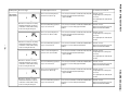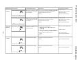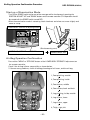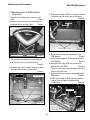
1
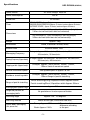
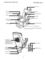
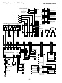
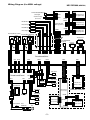
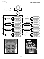
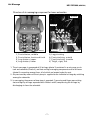
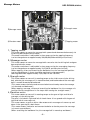
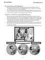
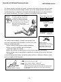
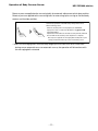
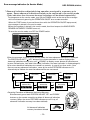
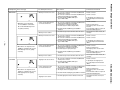
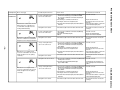
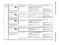
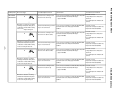
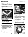
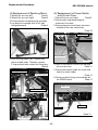
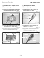
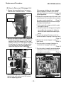
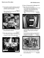
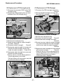
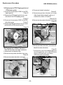
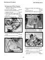
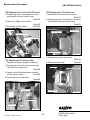
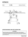
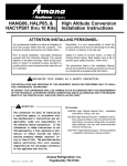
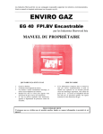
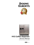
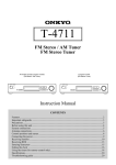
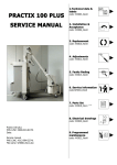
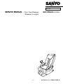
FILE No.
SERVICE MANUAL
Chair Type Massager
(Massager Lounger)
-1-
HEC-DR5000 (GENERAL)
REFERENCE NO. SM6510488-00
Specifications
Power source
HEC-DR5000 (GENERAL)
AC Local voltage 50/60 Hz
Power consumption
290 W
30 minutes
Rated time
Timer
Dimensions
(MANUAL COURSE) Approx. 15 minutes
(WHOLE BODY SENSOR AUTOMATIC COURSE) Approx. 15 minutes (maximum Approx. 20 minutes)
(AUTOMATIC COURSE) Approx. 15 minutes (maximum Approx. 20 minutes)
730 mm[width] x 1,240 mm[depth] x 1,200 mm[height]
* When not reclined (with foot rest retracted)
730 mm[width] x 1,940 mm[depth] x 680 mm[height]
* When reclined (with foot rest set horizontally)
Approx. 70kg
Weight
Accessories
Stand, Installation screws(Three)
Exterior cloth
Artificial leather 100%
Massaging Frequency
(5 stages) Approx. 10 times/min., 15 times/min., 20 times/min.,
25 times/min., 30 times/min.
Tapping Frequency (Upper body)
(5 stages) Approx. 300 times/min., 390 times/min., 480 times/min.,
540 times/min., 600 times/min.
Tapping width (Upper body)
Vertical movement speed
Backbone stretching width
(5 stages) Approx. 70mm, 85mm, 100mm, 115mm,
130mm Vartical movement speed
One up/down pass in approx. 35 sec.
(5 stages) Approx. 70mm, 85mm, 100mm, 115mm,
130mm Range of partial stretching
Range of partial stretching
Partial stretching(Long) :Repetition within Approx.200mm
Partial stretching(Short) :Repetition within Approx.100mm
Massaging balls up/down range
Approx. 720 mm
Height adjustment of
massaging balls
Reclining angle
Reclining method
Lower Body Massaging
(Air pressure)
No gradation or 2cm/one press of button
Approx. 120 - 170 degrees
Motor-driven type (Linked with foot rest)
Strong: Approx. 27kPa
Weak: Approx. 21kPa
- 2-
* There is a slight
difference according
to the part.
Name/Function of Each Part
HEC-DR5000 (GENERAL)
Head cover
Senser
Back rest
Remote control
Massage hands
Stand
Back pad
Arm rest
Seat cover
( 2 Air bags )
Foot rest
( 18 Air bags )
Reclining motors
Control unit
Air pump & Solenoids
Massage unit
Tapping motor
Massage motor
Strength motor
Elevation motor
LOCK switch
OPEN
LOCK
ON
Caster
POWER switch
Earthing screws
(for LOW voltage)
OFF
POWER
Power cord
Power plug
- 3-
Wiring Diagram (for LOW voltage)
HEC-DR5000 (GENERAL)
CN931
Limit Switch(UPPER)
(Strength)
Printed board
(Strength Pulse)
CN904
Volume Rotary
(Pressure)
CN903
CN902
CN905
Motor(Elevation)
CN911
Printed board
(Elevation Pulse)
Printed board
(Massage Pulse)
Motor(Strength)
Motor(Massage)
CN901
Motor(Tapping)
CN906
CN921
Printed board
(Tapping Pulse)
Reclining Motor(Foot Rest) Reclining Motor (Back Rest)
Switch
Motor
Motor
Switch
Main Harness
Transformer
Limit SW(UPPER)
(Elevation)
Reactor
CN25
CN24
CN8
CN9 CN10 CN11
CN19
CN23
CN12
CN16
CN13
Printed board(Main)
CN15
CN7 CN28
CN20
CN18
CN22
CN4
CN14
Valve (No.1)
Printed board(Power)
CN3
Valve (No.2)
CN5
CN6 CN27
CN1
CN2
CN17
CN21
CN1
Valve (No.3)
Thermistor
Valve (No.4)
Transformer
CN703
Printed board
(Remote Control)
Printed board
(Sensor Control)
(Remote Control)
Heater(Sole)
Valve (No.5)
Air Pump
Power Switch
Fuse
(250V 4A)
CN702
Valve (No.6)
Perspiration Sensor
CNB701
Valve (No.7)
Printed board
(Sensor Operation)
CNA701
Valve (No.8)
CN701
(Sensor)
AC
-4-
CNA791
Printed board
(Pulse Sensor)
Wiring Diagram (for HIGH voltage)
HEC-DR5000 (GENERAL)
CN931
Limit Switch(UPPER)
(Strength)
Printed board
(Strength Pulse)
CN904
Volume Rotary
(Pressure)
CN903
CN902
CN905
Motor(Elevation)
CN911
Printed board
(Elevation Pulse)
Printed board
(Massage Pulse)
Motor(Strength)
Motor(Massage)
CN901
Motor(Tapping)
CN906
CN921
Printed board
(Tapping Pulse)
Reclining Motor(Foot Rest) Reclining Motor (Back Rest)
Motor
Switch
Motor
Switch
Main Harness
Transformer
Limit SW(UPPER)
(Elevation)
Reactor
CN25
CN24
CN8
CN9 CN10 CN11
CN19
CN23
CN12
CN16
CN13
Printed board(Main)
CN15
CN7 CN28
CN20
CN18
CN22
CN4
CN14
Valve (No.1)
Printed board(Power)
CN3
Valve (No.2)
CN5
CN6 CN27
CN1
CN2
CN17
CN21
CN1
Valve (No.3)
Thermistor
Valve (No.4)
Transformer
CN703
Printed board
(Remote Control)
Printed board
(Sensor Control)
(Remote Control)
Heater(Sole)
Valve (No.5)
Valve (No.6)
Air Pump
Power Switch Fuse
(250V 4A)
CN702
Valve (No.7)
CNB701
Valve (No.8)
Printed board
(Sensor Operation)
CNA701
CN701
AC
(Sensor)
- 5-
Perspiration Sensor
CNA791
Printed board
(Pulse Sensor)
Air Wiring
HEC-DR5000 (GENERAL)
Air pump
compressing
decompressing
Air tank
1 Air bag
(Foot shiatsu, middle)
Exhaust
1 Solenoid
(Foot shiatsu, middle)
5 Solenoid
(Leg pinching)
1 Air bag
(Foot shiatsu, middle)
Exhaust
2 Solenoid
(Foot shiatsu,
back and forth)
2 Air bag
(Foot shiatsu,
back and forth)
Exhaust
3 Air bag
(Leg shiatsu, upper)
2 Air bag
(Foot shiatsu,
back and forth)
3 Solenoid
(Leg shiatsu, upper)
4 Air bag
(Leg shiatsu, lower)
4 Solenoid
(Leg shiatsu, lower)
5 Air bag
(Leg pinching)
Exhaust
6 Solenoid
(Foot pinching, outsaide)
6 Air bag
(Foot pinching, outsaide)
Exhaust
7 Air bag
(Foot pinching, insaide)
6 Air bag
(Foot pinching, outsaide)
7 Solenoid
(Foot pinching, insaide)
3 Air bag
(Leg shiatsu, upper)
Exhaust
5 Air bag
(Leg pinching)
Exhaust
7 Air bag
(Foot pinching, insaide)
8 Air bag
(Thigh, right , left)
Exhaust
8 Solenoid
(Thigh, right , left)
4 Air bag
(Leg shiatsu, lower)
8 Air bag
(Thigh, right , left)
Air tank
8
8
4
3
5
5
4
5
3
4
2
2
6 1 7
7 1 6
2
2
8
5
3
2
7
1
6
5
Air pump
Air bag position
Solenoid / Air pump position
- 6-
Air Massage
HEC-DR5000 (GENERAL)
Structure of air massaging component for lower extremites
Air hoses
Air tank
8
8
4
3
5
5
4
1,
2,
3,
4,
5
3
4
2
2
6 1 7
7 1 6
2
2
8
5
3
7
2
1
6
5
Solenoids
Air pump
Photo-1
Foot shiatsu, middle
Foot shiatsu, back and forth
Leg shiatsu, upper
Leg shiatsu, lower
5,
6,
7,
8,
Photo-2
Leg pinching
Foot pinching, outsid
Foot pinching, insaide
Thigh, right, left
1. The air massager is composed of 20 air bags (photo-1) contained in an air pump, an air
tank and solenoids (Photo-2), and foot and leg massaging components and of air hoses
(photo-2) connecting among them, all of which are located under the seat.
2. Air pressured by means of the air pump is supplied to the individual air bags by switching
among the solenoids.
3. In massaging, the process of two steps is repeated; 1) pressing and finger-pressurizing
feet and legs by air bags expanded with filled air and 2) compressing the air bags by
discharging air from the solenoids.
- 7-
Massage Motors
HEC-DR5000 (GENERAL)
2
2
1
3
3
2,Massage motor
3,Strength motor
4,Elevation motor
1,Tapping motor
4
4
1, Tapping motor
This motor rotates to move the massage balls upward and downward alternately via
the driving belt coupled to the motor.
(The motor revolutions is adjustable in three steps so that the tapping frequency
can be changed over to approximately 300,390,480,540 and 600 cycles/minute.)
2, Massage motor
This motor rotates to move the massage balls crosswise via the driving belt and gear
box coupled to the motor.
(The motor revolutions is adjustable in three steps so that the massaging frequency
can be changed over to approximately 10,15,20,25 and 30 cycles/minute.)
(When tapping, shiatu and stretching the backbone line, the massage ball position
can be changed over in three steps after starting the massagemotor.)
(Massage ball width approximately 70,85,100,115 and 130 mm.)
3, Strength motor
This motor rotates to transmit its rotating torque to the shaft screw via the driving
belt, whereby the massage unit is moved forward, and backward and the massage
balls is moved forward and backward.
(This motor rotates clockwise and counterclockwise to thereby move the massage
unit forward and backward.)
(When tapping, massage, shiatu and stretching the backbone line, the massage unit
position can be changed over in five steps after starting the strength motor.)
4, Elevation motor
This motor rotates to transmit its rotating torque to the gear of right and left of a
massage unit the driving belt.
The gear is included in right and left of a back frame. It has geared with the gear of
right and left of a massage unit.
This motor rotates, a gear on either side rotates and a massage unit moves up and
down in the gear top of a back frame.
(This motor rotates, clockwise and counterclockwise to thereby move the massage
unit move up and down.)
(When stretching the backbone line, the massage ball is moved up and down.)
-8-
Massage Motors
HEC-DR5000 (GENERAL)
Shoulder Gripping & Massaging
With the aid of a massage hand unit with a joint which moves freely like a thumb, a
massaging technique called "Grip/Grasp/Massage/Knead" for gripping and massaging
the muscles of shoulders has been reproduced.
This massaging technique has been reproduced by way of gripping the shoulders from
above while projecting the massage hands greatly together with a massage unit at the
back (maximum projection of massage hands: approx. 160mm).
Operation of Shoulder Gripping & Massaging
There are two large massage hands and two small massage hands at both ends of the
right and left massage arms. The small massage hands have the structure to move freely.
The massage hands move from side to side according to the operation of massage motors.
When the distance between the massage hands becomes narrower (the massage hands
move inwards), the massage hands move so that the clearance between the large
massage hands and the small massage hands becomes narrower.
Operation of shoulder gripping and massaging: Shoulder position is first measured, and
the massage hands project forward greatly only at the shoulder position and "grip and
massage the shoulders".
*The "shoulder gripping and massaging" function does not work on the back or the waist.
Large massage hands
Small massage hands
Narrow massage hands
Wide massage hands
-9-
Operation of Stiffness Detecting Sensor
HEC-DR5000 (GENERAL)
The sensor employs two types of sensors; an photo sensor and an electrical skin resistance
sensor for monitoring two physiological factors (pulse rate and perspiration respectively).
If stiffened position is subjected to stimulation of massage, the pulse rate and perspiration
will change accordingly. The sensor monitors such change in those two factors.
Sensor
Detection
A stimulation given to the stiffened or
sore muscle will cause vital reaction
considered to represent a change in
sensation such as better feeling with
comfortable pains. Monitoring such vital
reaction (perspiration and/or change in
pulse rate) concurrently enables
determination of the effectiveness of the
stimulation given.
Perspiration Pulse rate
When stimulated
and felt "stiffened"
Perspiration Pulse rate
increases
increases
STIFFNESS
The stiffness determined by a change in perspiration and
RELAX
HIGHT
pulse rate monitored will be indicated in real time on a level
Stiffness display
Indicates stiffness in real time by
meter of a remote controller.
monitoring fingers for any change
1;When relaxed, the perspiration tends to decrease.
in perspiration and pulse rate
during acupressure massage.
2;When in normal condition, each physiological
parameter shows less change.
3;When felt stiffened, the perspiration as well as pulse rate tends to increase.
4;When feeling a pain, the perspiration significantly increases and the pulse rate tends
to increase.
In the massage position display, the position where stiffness is detected (=the point needs
to be massaged) will be displayed.
Point that may be massaged.
STIFFNESS
Massage position display
Position where stiffness is detected
Indicates positions where the sensor detects
stiffness by monitoring perspiration and pulse rate that will
change when better feeling is given through stimulation
by massage.
- 10 -
Operation of Body Contour Sensor
HEC-DR5000 (GENERAL)
Detects a pressure applied to the massasing balls for automatic adjustment to their best position.
Detects a pressure applied to the massasing balls for measuring spine curving to find out body
contour and shoulder position.
Corrects the positions automatically if the posture varies
when reclining a seat.
(When the shoulder position is being adjusted, the "SHOULDER"
display of the remote controller turns ON with the "UP( )/DOWN ( )"
display kept blinking.
Adjustment is finished when the "Shoulder Set" lamp turns ON, which will
then turn OFF after the shoulder position adjustment is completed.)
Detects pressure applied to the massaging balls that depends on spine
curving, and determined its body contour and shoulder position.
* Unless the massaging balls receive a body weight pressure from user for a certain time
during sensor automatic course or automatic course, the operation will discontinue with
the massaging balls retracted.
- 11 -
Error message indication (in Service Mode)
HEC-DR5000 (GENERAL)
*Abnormal indications detected during operation are stored in a memory up to
seven. Seven abnormal indications stored can be confirmed in the service mode
(Older indications than the seven abnormal indications will be deleted sequentially).
To change over to the service mode, turn ON the POWER switch at the rear of the massager
while simultaneously pressing the OPERATION ON/OFF on a remote controller.
When the "FINE" button is pressed three times with the OPERATION ON/OFF kept pressed,
the massager is placed in the service mode.
(When the massager is placed in the service mode, four blue lamps at the WHOLE BODY
SENSOR AUTOMATIC COURSE come on).
To reset the service mode, turn OFF the POWER switch.
OPEN
LOCK
ON
OFF
POWER
POSITION ADJUST "UP" "DOWN" button
"OPERATION ON/OFF" button
POWER switch "ON"
"FINE" button (three times)
When the massager is placed in the service mode, the latest abnormal indication is displayed.
The POSITION ADJUST " (UP)" button of the remote controller is used to display older
abnormal indications one by one, and " (DOWN)" to display newer abnormal indication one
by one (Following the sixth older (the oldest) indication, the latest indication is displayed again).
Up to seven abnormal indications are stored in a memory. In case of less than seven, since
there are not any abnormal indications, some of the seven STIFFNESS indicators are lit
alternatively to indicate the state that abnormalities are not stored.
Latest
abnormality
"UP"
Next older
abnormality
"UP"
The oldest
abnormality
Second older
abnormality
"DOWN"
"DOWN"
"DOWN"
"UP"
"DOWN"
Fifth older
abnormality
"UP"
"UP"
"DOWN"
"DOWN"
Fourth older
abnormality
"UP"
STIFFNESS
- 12 -
RELAX
"DOWN"
"UP"
<Resetting Procedure of Abnormal Indication Memory>
Simultaneously press both POSITION ADJUST "UP" and "DOWN"
buttons on the remote controller to delete all abnormal indication
memory (When the seven STIFFNES indicators are all lit up, all
abnormal indication memory have been deleted).
All abnormal indication
memory have been deleted
Third older
abnormality
HIGHT
POWER
REMOTE
CONTROL
- 13 SENSER
Troubled phenomenon
Nothing is displayed after the
power ON.
Check item
Counteraction method
1. Check the current fuse for fusion.
2. Check the Printed board (Power) CN1 output (AC100V).
3. Check the Printed board (Power) CN6 output (AC100V).
4. Check the Printed board (Main) CN7 output (AC100V).
5. Check the Printed board (Main) CN16 output (approx. AC24V).
6. Check the Printed board (Main) CN21 for connector come-off.
7. Check the Printed board (Remote control) CN1 for connector
come-off.
8. Check the Connector (remote control) for disconnection or
shorting.
9. Others.
Replace the current fuse.
Check the power switch and power cord.
Check the Printed board (Power).
Check the Connector (Printed board) .
Replace the transfomer.
Insert the connector.
Insert the connector.
It displays after [ remote control
communication impossible ]
3 seconds.
(When Printed board (Main)
detects)
1. The connection confirmation of Printed board (Main) CN21.
2. The connection confirmation of Printed board (Remote control)
CN1.
3. Check the Connector (Remote control) for disconnection or
shorting.
4. Others.
It displays after [ remote control
communication impossible ]
3 seconds.
(When Printed board (Remote
control) detects)
1. The connection confirmation of Printed board (Main) CN21.
2. The connection confirmation of Printed board (Remote control)
CN1.
3. Check the Connector (Remote control) for disconnection or
shorting.
4. Others.
It displays after [ sensor
communication impossible ]
3 seconds.
(When Printed board (Main)
detects)
1. The connection confirmation of Printed board (Main) CN22.
2. The connection confirmation of Printed board (Sensor ) CN703.
3. Check the Connector (Sensor) cable for disconnection or
shorting.
4. Others.
It displays after [ sensor
communication impossible ]
3 seconds.
(When Printed board (Senser)
detects)
1. The connection confirmation of Printed board (Main) CN22.
2. The connection confirmation of Printed board (Sensor control)
CN703.
3. Check the Connector (Sensor) cable for disconnection or
shorting.
4. Others.
Indication does not disappear.
"Grip the Sensor"
1. The connection confirmation of Printed board (Sensor )CN701,
CN702.
Replace the Connector (Remote control) .
Replace the Printed board (Remote control)
or Printed board (Main).
Insert the connector.
Insert the connector.
Problem Diagnosis Chart
Troubled portion Error message
Replace the Connector (Remote control) .
Replace the Printed board (Remote control)
or Printed board (Main).
Insert the connector.
Insert the connector.
Replace the Connector (Remote control) .
Replace the Printed board (Remote control)
or Printed board (Main).
Insert the connector.
Insert the connector.
Replace the Connector (Sensor) .
Replace the Printed board (Sennsor ) or
Printed board (Main).
Insert the connector.
Insert the connector.
Replace the Connector (Sensor) .
Insert the connector.
*Be sure to grip the sensor.
*When the user's skin is gry (espeially a person with dry skin), yhe degree of stiffness may
not be measured correctly.
In such a case, slightly moisten with the fingers using hand cream.
HEC-DR5000 (GENERAL)
Replace the Printed board (Sennsor ) or
Printed board (Main).
MASSAGE
*When there is not output level
at sensor(IC902) for continuation
30 seconds while Massage motor
are getting erectricity.
- 14 -
*When there is no output at sensor
(IC902) for continuation 15 seconds
while Massage motor are getting
erectricity.
TAPPING
Troubled phenomenon
Check item
Counteraction method
Massage mode doesn't move.
1. The connection confirmation of Printed board (Main) CN9
and the junction connector.
2. The connection confirmation of Printed board (Main) CN19
and Printed board (Massage pulse) CN901.
3. Check the Printed board (Main) CN9 output
(approx. DC60 - 100V).
Insert the connector.
A stop of massaging motion
can not be carried out.
1. The connection confirmation of Printed board (Main) CN19
and Printed board (Massage pulse) CN901.
2. Check turning on confirmation main harness.
3. Check the magnet in a Holder (magnet width) .
4. Check the Printed board (Massage pulse) IC902 for
inclination.
Insert the connector.
If output Replace the massage motor.
If no output Replace the Printed board
(Main).
Insert the connector.
Replace the main harness.
The magnet position correction for the
detection.
Correct the tilted condition or replace the
Printed board (Massage pulse).
Massage motor rotation.
1. Check the massage motor belt for dislocation and cut-off.
The massage motor belt correction, the
exchange.
Massage mode doesn't move.
1. The connection confirmation of Printed board (Main) CN9
and the junction connector.
2. The connection confirmation of Printed board (Main) CN19
and Printed board (Massage pulse) CN901.
3. Check the Printed board (Main) CN7 output
(approx. DC60 - 100V).
Insert the connector.
A stop of massaging motion
can not be carried out.
1. The connection confirmation of Printed board (Main) CN19
and Printed board (Massage pulse) CN901.
2. Check turning on confirmation main harness.
3. Check the magnet in a pulley (massage) .
4. Check the Printed board (Massage pulse) IC901 for
inclination.
Insert the connector.
If output Replace the massage motor.
If no output Replace the Printed board
(Main).
Insert the connector.
Replace the main harness.
The magnet position correction for the
detection.
Correct the tilted condition or replace the
Printed board (Massage pulse).
Massage motor rotation.
1. Check the massage motor belt for dislocation and cut-off.
The massage motor belt correction, the
exchange.
Tapping mode doesn't move.
1. The connection confirmation of Printed board (Main) CN8
and the junction connector.
2. Check the Printed board (Main) CN8 output
(approx. DC60 - 100V).
Insert the connector.
*When there is no output†at sensor
(IC921) for continuation 15 seconds
while tapping motor are getting
erectricity.
Tapping motor rotation.
If output Replace the tapping motor.
If no output Replace the Printed board
(Main).
1. The connection confirmation of Printed board (Main) CN19
and Printed board (Massage pulse) CN901 and CN906.
2. Check turning on confirmation main harness.
3. The magnet check for the tapping detection.
Insert the connector.
1. Check the tapping motor belt for dislocation and cut-off.
The tapping motor belt correction, the
exchange.
Replace the main harness.
The magnet position correction for the
detection.
4. Check the Printed board (Tapping pulse) IC921 for inclination. Correct the tilted condition or replace the
Printed board (Tapping pulse).
HEC-DR5000 (GENERAL)
A stop of tapping motion
can not be carried out.
Problem Diagnosis Chart
Troubled portion Error message
STRENGTH
When there is no detection of lower
limit position for continuation 15
seconds while strength motor are
moving downward way.
When there is no detection of upper limit
position for continuation 15 seconds while
strength motor are moving upper ward way.
Troubled phenomenon
Check item
Counteraction method
A stop of strength motion
can not be carried out.
1. The connection confirmation of Printed board (Main) CN19
and Printed board (Massage pulse) CN901 and CN902.
The connection confirmation of Printed board (Strength
pulse) CN931.
2. Check turning on confirmation main harness.
3. The magnet check for the strength detection.
Insert the connector.
4. Check the Printed board (Strength pulse) IC931, IC932 for
inclination.
Strength motor rotation.
1. Check the strength motor belt for dislocation and cut-off.
The elevation motor belt correction, the
exchange.
A stop of strength motion
can not be carried out.
1. The connection confirmation of Printed board (Massage
pulse) CN904
2. Check the limit switch(strength).
3. Others.
Insert the connector.
Strength motor rotation.
1. Check the strength motor belt for dislocation and cut-off.
The strength motor belt correction, the
exchange.
A stop of strength motion
can not be carried out.
1. The connection confirmation of Printed board (Main) CN19
and Printed board (Massage pulse) CN901 and CN902.
The connection confirmation of Printed board (Strength
pulse) CN931.
2. Check turning on confirmation main harness.
3. The magnet check for the strength detection.
Insert the connector.
- 15 When there is not output level at
sensor for continuation 15 seconds
while strength motor are getting
erectricity.
4. Check the Printed board (Strength pulse) IC931, IC932 for
inclination.
Replace the switch(strength).
Replace the Printed board (Main).
Replace the main harness.
The magnet position correction for the
detection.
Correct the tilted condition or replace the
Printed board (Strength pulse).
Strength motor rotation.
1. Check the strength motor belt for dislocation and cut-off.
The strength motor belt correction, the
exchange.
Strength mode doesn't move.
1. The connection confirmation of Printed board (Main) CN10
and the junction connector.
2. Check the Printed board (Main) CN10 output
(approx. DC60 - 100V).
Insert the connector.
A stop of strength motion
can not be carried out.
1. The connection confirmation of Printed board (Main) CN19
and Printed board (Massage pulse) CN901 and CN902.
The connection confirmation of Printed board (Strength
pulse) CN931.
2. Check turning on confirmation main harness.
3. The magnet check for the strength detection.
4. Check the Printed board (Strength pulse) IC931, IC932 for
inclination.
Strength motor rotation.
1. Check the strength motor belt for dislocation and cut-off.
If output Replace the strength motor.
If no output Replace the Printed board
(Main).
Insert the connector.
Replace the main harness.
The magnet position correction for the
detection.
Correct the tilted condition or replace the
Printed board (Strength pulse).
The strength motor belt correction, the
exchange.
HEC-DR5000 (GENERAL)
When there is not output level at
sensor for continuation 15 seconds
while strength motor are getting
erectricity.
Replace the main harness.
The magnet position correction for the
detection.
Correct the tilted condition or replace the
Printed board (Strength pulse).
Problem Diagnosis Chart
Troubled portion Error message
ELEVATION
When there is no detection of lower
limit position for continuation 30
seconds while elevation motor are
moving downward way.
When there is no detection of upper limit
position for continuation 30 seconds while
elevation motor are moving upper ward way.
- 16 When there is not output level at
sensor(IC912) for continuation 30
seconds while elevation motor are
getting erectricity.
Check item
Counteraction method
A stop of elevation motion
can not be carried out.
1. The connection confirmation of Printed board (Main) CN19
and Printed board (Massage pulse) CN901 and CN905.
The connection confirmation of Printed board (Elevation
pulse) CN911.
2. Check turning on confirmation main harness.
3. The magnet check for the elevation detection.
Insert the connector.
4. Check the Printed board (Elevation pulse) IC912 for
inclination.
Replace the main harness.
The magnet position correction for the
detection.
Correct the tilted condition or replace the
Printed board (Elevation pulse).
Elevation motor rotation.
1. Check the elevation motor belt for dislocation and cut-off.
The elevation motor belt correction, the
exchange.
A stop of elevation motion
can not be carried out.
1. The connection confirmation of Printed board (Main) CN23
Insert the connector.
2. Check the limit switch(elevation).
3. Others.
Replace the switch(elevation).
Replace the Printed board (Main).
Elevation motor rotation.
1. Check the elevation motor belt for dislocation and cut-off.
The elevation motor belt correction, the
exchange.
A stop of elevation motion
can not be carried out.
1. The connection confirmation of Printed board (Main) CN19
and Printed board (Massage pulse) CN901 and CN905.
The connection confirmation of Printed board (Elevation
pulse) CN911.
2. Check turning on confirmation main harness.
3. The magnet check for the elevation detection.
Insert the connector.
4. Check the Printed board (Elevation pulse) IC912 for
inclination.
Replace the main harness.
The magnet position correction for the
detection.
Correct the tilted condition or replace the
Printed board (Elevation pulse).
Elevation motor rotation.
1. Check the elevation motor belt for dislocation and cut-off.
The elevation motor belt correction, the
exchange.
Elevation mode doesn't move.
1. The connection confirmation of Printed board (Main) CN11
and the junction connector.
2. Check the Printed board (Main) CN11 output
(approx. DC60 - 100V).
Insert the connector.
A stop of elevation motion
can not be carried out.
1. The connection confirmation of Printed board (Main) CN19
and Printed board (Massage pulse) CN901 and CN905.
The connection confirmation of Printed board (Elevation
pulse) CN911.
2. Check turning on confirmation main harness.
3. The magnet check for the elevation detection.
4. Check the Printed board (Elevation pulse) IC911 for
inclination.
Elevation motor rotation.
1. Check the elevation motor belt for dislocation and cut-off.
If output Replace the elevation motor.
If no output Replace the Printed board
(Main).
Insert the connector.
Replace the main harness.
The magnet position correction for the
detection.
Correct the tilted condition or replace the
Printed board (Elevation pulse).
The elevation motor belt correction, the
exchange.
HEC-DR5000 (GENERAL)
When there is not output level at
sensor(IC911) for continuation 30
seconds while elevation motor are
getting erectricity.
Troubled phenomenon
Problem Diagnosis Chart
Troubled portion Error message
Troubled phenomenon
Check item
Counteraction method
RECLINING
BACK REST
The back rest reclining motion
doesn't move. (Don't up)
1. The connection confirmation of Printed board (Power) CN4.
2. Check the Printed board (Power) CN4 output
(approx. DC100V).
Insert the connector.
If output Replace the reclining motor
(back rest).
If no output Replace the Printed board
(Power).
A back rest lilacinning operation
stop is not carried out.
1. The connection confirmation of Printed board (Main) CN24.
2. Check the back rest reclining upper limit switch.
3. Others.
Insert the connector.
Replace the reclining motor (back rest).
Replace the Printed board (Main).
The back rest reclining motion
doesn't move. (Don't down)
1. The connection confirmation of Printed board (Power) CN4.
2. Check the Printed board (Power) CN4 output
(approx. DC100V).
Insert the connector.
If output Replace the reclining motor
(back rest).
If no output Replace the Printed board
(Power).
When there is no detection of reclining
switch(upper limit) at the back part for
continuation 1 minutes while reclining
motor are moving for raising seat.
- 17 -
When there is no detection of reclining
switch(lower limit) at the back part for
continuation 1 minutes while reclining
motor are moving for lower seat.
When there is detection of reclining
switch(upper limit) at the back part for
continuation 1 minutes while reclining
motor are moving for lower seat.
Insert the connector.
Replace the reclining motor (back rest).
Replace the Printed board (Main).
The back rest reclining motion
doesn't move. (Don't down)
1. The connection confirmation of Printed board (Power) CN4.
2. Check the Printed board (Power) CN4 output
(approx. DC100V).
Insert the connector.
If output Replace the reclining motor
(back rest).
If no output Replace the Printed board
(Power).
A back rest lilacinning operation
stop is not carried out.
1. The connection confirmation of Printed board (Main) CN24.
2. Check the back rest reclining upper limit switch.
3. Others.
Insert the connector.
Replace the reclining motor (back rest).
Replace the Printed board (Main).
The back rest reclining motion
doesn't move. (Don't up)
1. The connection confirmation of Printed board (Power) CN4.
2. Check the Printed board (Power) CN4 output
(approx. DC100V).
Insert the connector.
If output Replace the reclining motor
(back rest).
If no output Replace the Printed board
(Power).
A back rest lilacinning operation
stop is not carried out.
1. The connection confirmation of Printed board (Main) CN24.
2. Check the back rest reclining lower limit switch.
3. Others.
Insert the connector.
Replace the reclining motor (back rest).
Replace the Printed board (Main).
HEC-DR5000 (GENERAL)
When there is detection of reclining
switch(lower limit) at the back part for
continuation 1 minutes while reclining
motor are moving for raising seat.
A back rest lilacinning operation 1. The connection confirmation of Printed board (Main) CN24.
2. Check the back rest reclining lower limit switch.
stop is not carried out.
3. Others.
Problem Diagnosis Chart
Troubled portion Error message
Check item
Counteraction method
RECLINING
FOOT REST
The foot rest reclining motion
doesn't move. (Don't up)
1. The connection confirmation of Printed board (Power) CN5.
2. Check the Printed board (Power) CN5 output
(approx. DC100V).
Insert the connector.
If output Replace the reclining motor
(foot rest).
If no output Replace the Printed board
(Power).
A foot rest lilacinning operation
stop is not carried out.
1. The connection confirmation of Printed board (Main) CN25.
2. Check the foot rest reclining upper limit switch.
3. Others.
Insert the connector.
Replace the reclining motor (foot rest).
Replace the Printed board (Main).
The foot rest reclining motion
doesn't move. (Don't down)
1. The connection confirmation of Printed board (Power) CN5.
2. Check the Printed board (Power) CN5 output
(approx. DC100V).
Insert the connector.
If output Replace the reclining motor
(foot rest).
If no output Replace the Printed board
(Power).
A foot rest lilacinning operation
stop is not carried out.
1. The connection confirmation of Printed board (Main) CN25.
2. Check the foot rest reclining lower limit switch.
3. Others.
Insert the connector.
Replace the reclining motor (foot rest).
Replace the Printed board (Main).
The foot rest reclining motion
doesn't move. (Don't down)
1. The connection confirmation of Printed board (Power) CN5.
2. Check the Printed board (Power) CN5 output
(approx. DC100V).
Insert the connector.
If output Replace the reclining motor
(foot rest).
If no output Replace the Printed board
(Power).
A foot rest lilacinning operation
stop is not carried out.
1. The connection confirmation of Printed board (Main) CN25.
2. Check the foot rest reclining upper limit switch.
3. Others.
Insert the connector.
Replace the reclining motor (foot rest).
Replace the Printed board (Main).
The foot rest reclining motion
doesn't move. (Don't up)
1. The connection confirmation of Printed board (Power) CN5.
2. Check the Printed board (Power) CN5 output
(approx. DC100V).
Insert the connector.
If output Replace the reclining motor
(foot rest).
If no output Replace the Printed board
(Power).
A foot rest lilacinning operation
stop is not carried out.
1. The connection confirmation of Printed board (Main) CN25.
2. Check the foot rest reclining lower limit switch.
3. Others.
Insert the connector.
Replace the reclining motor (foot rest).
Replace the Printed board (Main).
When there is no detection of reclining
switch(upper limit) at the foot part for
continuation 1 minutes while reclining
motor are moving for raising seat.
- 18 -
When there is no detection of reclining
switch(lower limit) at the foot part for
continuation 1 minutes while reclining
motor are moving for lower seat.
When there is detection of reclining
switch(upper limit) at the foot part for
continuation 1 minutes while reclining
motor are moving for lower seat.
When there is detection of reclining
switch(lower limit) at the foot part for
continuation 1 minutes while reclining
motor are moving for raising seat.
HEC-DR5000 (GENERAL)
Troubled phenomenon
Problem Diagnosis Chart
Troubled portion Error message
HERTER
Troubled phenomenon
When there is thermistor output
of continuation 2 second and
more then 4.9V.
Check item
Counteraction method
1. The connection confirmation of Printed board (Main) CN20.
Insert the connector.
Replace the Connector ass'y (heater).
Replace the heater(sole).
Replace the Printed board (main).
2. Check the Connector ass'y (heater) for disconnection.
3. Check the Thermistor for disconnection.
4. Others.
PRESSURE
SENSOR
- 19 -
When there is thermistor output 1. The connection confirmation of Printed board (Main) CN20.
2. Check the Connector ass'y (heater) for shorting.
of continuation 2 second and
less then 0.1V.
3. Check the Thermistor for shorting.
4. Others.
Insert the connector.
Replace the Connector ass'y (heater).
Replace the heater(sole).
Replace the Printed board (main).
1. Check the volume rotary (pressure) .
When there is pressure sensor
output of Continuation 3 second
(CN903 red-black approx. 10k /red-white approx.
and less then 0.1V.
250 - 10k )
2. The connection confirmation of Printed board (Main) CN19
and Printed board (Massage pulse) CN901 and CN903.
Replace the volume rotary (pressure).
8. Check the main harness for disconnection or
shorting.
Problem Diagnosis Chart
Troubled portion Error message
Insert the connector.
Replace the main harness.
Replace the Printed board (main).
4. Others.
OTHERS
An abnormal power supply.
Replace the Printed board (main).
1. Check the power supply of an power point.
2. Others.
Replace the Printed board (main).
HEC-DR5000 (GENERAL)
An abnormal power supply.
1. Check the power supply of an power point.
2. Others.
Air-Bag Operation Confirmation Procedure
HEC-DR5000 (GENERAL)
Start-up of Examination Mode
Turn ON the POWER switch at the rear of the massager while simultaneously pressing the
POSITION ADJUST "UP" and "DOWN" buttons on the remote controller (This operation should
be started with the POWER switch turned OFF).
When the examination mode is started up, both a backrest and a foot rest move slightly and
come to a stop.
LOWER BODY STRENGTH adjusting button
OPEN
LOCK
ON
OFF
(Simultaneously press)
POSITION ADJUST "UP" and "DOWN" buttons
POWER
POWER switch "ON"
Air-Bag Operation Confirmation
Press either "WEAK" or "STRONG" button of the LOWER BODY STRENGTH adjustment on
the remote controller.
Check if the air-bag inflates sequentially as shown below.
* If there are any problems, check air leakage, breakage of air hoses, and the air-bag.
1, Foot pinching, outside
2, Foot pinching, inside
8
8
3, Foot shiatsu, middle
4, Foot shiatsu, back and forth
7
5
5
6
5
7
6
5, Leg pinching, inside, outside
5
6, Leg shiatsu, lower
4
4
1 3 2
2 3 1
4
4
7, Leg shiatsu, upper
8, Thigh, right, left
- 20 -
Replacement Procedure
HEC-DR5000 (GENERAL)
(1) Replacement of PCBs (main)
& (power)
1, Take off four thread caps on an arm rest
(left).
Photo-1
2, Remove four set screws on the elbow rest
and take off the arm rest (left).
Photo-1
5, Remove two cover (PCB) set screws and take
off latches of ribs at the rear of the cover.
Photo-3
Cover (PCB)
Arm rest (left)
Cover (PCB) set screws
Photo-3
Arm rest set screws
Thread caps
Photo-1
3, Lift up a foot rest and insert a screwdriver
and so forth into a link to fix the link.
Photo-2
4, Remove four cover (under front) set screws
and take off the cover (under front).
Photo-2
Driver, etc
Cover (under front)
6, Disconnect connectors connected to the
PCB (power).
Photo-4
7, Unfix seven stoppers (PCB) and take off the
PCB (power).
Photo-4
8, Remove three stay (PCB) set screws and
take off the stay (PCB).
Photo-4
* There is a set screw around under a reclining
motor at the left side.
9, Disconnect the connectors connected to the
PCB (main).
Photo-4
10, Unfix nine stoppers (PCB) from the bottom
side of the massager and take off the
PCB (main).
Photo-4
PCB (power)
Stoppers
Cover set screws
Photo-2
PCB (main)
Stay (PCB) set screws
- 21 -
Photo-4
Replacement Procedure
HEC-DR5000 (GENERAL)
(2) Replacement of Solenoid
1, Remove one cord holder set screw and unfix
two remote controller cords.
Photo-5
2, Take off four thread caps on the arm rest
(right).
Photo-5
3, Remove four elbow rest set screws and take
off the arm rest (right).
Photo-5
Insulator
Solenoid
Stay (valve) set screw
Arm rest (right)
Cord holder
Cover(Air pump) set screws
Photo-6
(3) Replacement of Air Pump,
Transformer Reactor
Arm rest set screws
Thread caps
Photo-5
4, Disconnect each air hose.
*When taking off the air hoses, indicate a
mark such as number, symbol
(Exercise care so as not to make a
mistake in connecting the hoses).
5, Remove the cord processing of a solenoid
(upper step).
Photo-6
6, Remove two solenoid (upper step) set screws
and take off the solenoid (upper step).
Photo-6
7, Remove two stay (valve) set screws and take
off the stay (valve).
* There are screws behind an insulator on the
left side surface.
Photo-6
8, Remove the cord processing of a solenoid
(lower step).
Photo-6
9, Remove two solenoid (lower step) set screws
and take off the solenoid (lower step).
Photo-6
1, Remove two cover(air pump) set screws and
take off the cover(air pump).
Photo-6
2, Take off the cord processing of an air pump.
3, Remove four fixing rubbers of the air pump
and take off the air pump.
Photo-7
4, Take off the cord processing of a transformer.
5, Remove two transformer set screws and take
off the transformer.
Photo-7
6, Take off the cord processing of a reactor.
7, Remove two reactor set screws and take
off the reactor.
Photo-7
- 22 -
Transformer
Reactor
Set screws
Set screws
Air pump
Photo-7
Replacement Procedure
HEC-DR5000 (GENERAL)
(4) Replacement of Reclining Motor
(5) Replacement of Power Switch
and Current Fuse
1, Take off the arm rest (left).
Photo-1
2, Take off the arm rest (right).
Photo-5
3, Disconnect each cord processing and cords.
4, Lay down the massager with its left side
facing downward.
Photo-8
1, Take off the arm rest (right).
Photo-5
2, Remove each cord processing and
disconnect the cords.
3, Remove two case (switch box) set screws
and take off the case (switch box).
Photo-10
Case (switch box)
Connector (sensor)
Connector (remote control)
Photo-8
Case set screws
5, Each reclining motor (set) is fixed at two
places on both ends. Therefore, remove
E rings on both ends and pull out fixing pins.
Photo-9
Photo-10
4, Open a fuse case of current fuses and take
out a current fuse.
Photo-11
5, Remove two switch holder set screws and
take off a switch holder.
Photo-11
6, Remove a switch fixing screw and take off
the POWER switch.
Photo-11
Reclining motor (back rest)
E rings & fixing pins
POWER switch
Switch holder set screws
Reclining motor (foot rest)
Reclining motor (back rest)
Reclining motor (foot rest)
Power cord
Current fuse
Photo-11
E rings & fixing pins
Photo-9
- 23 -
Replacement Procedure
HEC-DR5000 (GENERAL)
(6) Replacement of Remote Control
(7) Replacement of Sensor
1, Remove each cord processing and
disconnect the cords.
2, Remove nine remote control case set screws
and take off a remote control case (lower).
Photo-12
1, Remove each cord processing and
disconnect the cords.
2, Remove two sensor case set screws and
take off a sensor case (upper).
Photo-14
Remote control case set screws
Sensor case (upper)
Sensor case set screws
Remote control case (lower)
Photo-14
Photo-12
3, Remove two PCB (remote control) set screws
and take off the PCB (remote control)
Photo-13
4, Disconnect the interconnecting connector
CN1 of the connector (remote control).
Photo-13
3, Remove one PCB (sensor) set screw and
take off the PCB (sensor).
Photo-15
4, Disconnect the interconnecting connector
CN703 of the connector (sensor).
Photo-15
PCB (remote control)
PCB (sensor)
PCB set screws
PCB set screw
Connector(sensor)
CN703
Connector (remote control)
CN1
Photo-15
Photo-13
- 24 -
Replacement Procedure
HEC-DR5000 (GENERAL)
(8) How to Remove A Massage Unit
1, Remove four cover(back cover) set screws
and take off a cover(back cover). Photo-16
If the massage unit does not move upwards
when the power is turned on, turn a pulley
(elevation) clockwise to move the massage unit
to the top position.
Photo-17
Cover(back cover)
Cover(back cover)
set screws
Photo-16
2, Move the massage unit upwards to its top position.
Usually the massage unit is at a stop at its top
position. When the massage unit is at a stop
halfway, however, turn on the power and make
the massage unit move up to its top position.
At the top position, when the massage unit
comes to a stop, pull out a POWER plug.
Photo-17
Massage unit
3, Remove the cord processing of the cord (main)
and disconnect the connectors (four connectors
for motors, one for signal line).
Photo-18
Remove one earthing set screw and cut eight
insulation lock black cords.
* Cut the cords with a nipper so that the cords
do not get scratched.
* In order to restore the wiring processing after
reassembling the massage unit, indicate a
markon the cords before disconnecting the
wiring.
4, Remove one spring A (harness main) set
screw and take off a spring A (harness main).
Photo-18
5, Remove two screws(stopper) inside of a
back frame.
Photo-18
6, Turn the pulley (massage) clockwise to
minimize the massage hand width.
Photo-18
7, Turn the pulley (strength) counterclockwise
to bring to minimum position (maximum
strength) of a thread bar.
Photo-18
Screw (stopper)
Moving
upwards
Pulley (massage)
Pulley (strength)
Spring A(main harness )
Pulley (elevation)
Connector (main)
POWER switch
Photo-17
Spring A(main harness )
* While the massage unit is moving upwards,
exercise care so as not to come into contact
with the operating portion.
Connector ass'y (main)
- 25 -
Photo-18
Replacement Procedure
HEC-DR5000 (GENERAL)
(9) How to Reassemble the Massage Unit
1, Tape a lever of a micro switch.
For the purpose of preventing the lever of the
micro switch from being deformed or
damaged by incidentally hitting it when
installing the massage unit.
* After installing the massage unit, peel the
tape.
Photo-21
8, Turn the pulley (evevation) clockwise, move the
massage unit upwards, and take off a driving
wheel from a back frame guide.
Photo-19
* When taking off the driving wheel, hold the
massage unit firmly.
Driving wheel
Tape the lever to
protect it.
Pulley (evevation)
Micro switch
Move upwards
Photo-21
Photo-19
9, With a guide roller removed, further turn the
pulley (evevation) clockwise.
Photo-20
10, When right and left gears are disengaged
from the back frame gears (rack), take off the
massage unit from the massager body.
Photo-20
2, Before fitting the massage unit into the
massager body, minimize massage hand
width by turning the pulley (massage)
clockwise.
Turn the pulley (strength) counterclockwise
to bring to minimum position (maximum
strength) of a thread bar.
Photo-22
Pulley (strength)
Pulley (massage)
Gears
Photo-22
3, Fit the massage unit in parallel so that the
first right and left gear (rack) teeth engage
with the right and left gears of the massage
unit simultaneously.
Photo-22
Pulley (evevation)
Photo-20
- 26 -
Replacement Procedure
HEC-DR5000 (GENERAL)
(10) Replacement of PCB (strength pulse)
(12) Replacement of PCB (Massage)
1, Disconnect the connector CN931 of the PCB
(strength pulse).
Photo-23
2, Remove one PCB (strength pulse) set screw
and take off the PCB (strength pulse).
Photo-23
1, Disconnect five PCB (massage) connectors.
Photo-25
2, Remove two PCB (massage) set screws and
Photo-25
take off the PCB (massage).
Belt (massage)
Motor set screws
PCB (strength pulse)
PCB set screw
Motor set screws
PCB set screw
PCB (massage pulse)
Photo-25
Motor (massage)
Motor (strength)
(13) Replacement of Motor (Massage)
Belt(strength)
Photo-23
(11) Replacement of Motor (strength)
1, Remove each cord processing.
2, Remove two stay (under the motor (strength))
set screws. Photo-24
3, Disconnect the belt (strength).
Photo-23
4, Remove two motor (strength) set screws and
take off the motor (strength) and the stay
(under the motor (strength)). Photo-23, 24
5, Remove two motor (strength) set screws and
take off the motor (strength).
* Exercise care so as not to adhere grease to
the driving portions such as belt
(Failure to observe this precaution may lead
to malfunction due to slippage).
1, Remove each cord processing.
2, Disconnect the belt (massage).
Photo-25
3, Remove two motor (massage) set screws.
Photo-25
4, Remove two stay (under the motor (massage))
set screws and take off the motor (massage).
and the stay (under the motor (massage)).
Photo-26
5, Remove one motor (massage) set screw and take
Photo-26
off the motor (massage).
* Exercise care so as not to adhere grease to
the driving portions such as belt (Failure to
observe this precaution may lead to
malfunction due to slippage).
Motor (massage)
Motor (strength)
Motor set screw
Stay set screw
Stay set screw
Stay (under the Motor (strength))
Stay (under the massage motor)
Photo-24
- 27 -
Photo-26
Replacement Procedure
HEC-DR5000 (GENERAL)
(14) Replacement of PCB (Tapping pulse) and
PCB(elvation pulse)
4, Disconnect the belt (elevation).
1, Disconnect the connector CN921 of the PCB
(tapping pulse).
Photo-27
2, Remove one PCB (tapping pulse) set screw
and take off the PCB (tapping pulse).
Photo-27
3, Disconnect the connector CN911 of the PCB
(elevation pulse).
Photo-27
4, Remove two PCB (elevation pulse) set screws
and take off the PCB (elevation pulse).
Photo-27
Photo-29
5, Remove two gear box (elevation) set screws,
slide the gear box outwards, and turn it
clockwise as shown in Photo-30.
Photo-29, 30
6, Remove two stay motor (elevation) set screws.
Photo-29
Motor (elevation)
Stay (Motor (elevation))
PCB set screws
Stay set screw
Belt (elevation)
PCB (tapping pulse)
Gear box set screw
Photo-29
PCB (elevation pulse)
PCB set screw
7, Remove two motor (elevation) set screws and
take off the motor (elevation).
Photo-30
* Exercise care so as not to adhere grease to
the driving portions such as belt (Failure to
observe this precaution may lead to
malfunction due to slippage).
Photo-27
(15) Replacement of Motor (elevation)
* Take off the motor (massage) in advance.
1, Remove each cord processing.
2, Remove two stay motor (elevation) set screws.
Photo-28
3, Remove two motor (elevation) set screws.
Photo-28
Stay (Motor (elevation))
Motor set screw
Motor (elevation)
Turn
Stay set screw
Motor set screw
Motor (elevation)
Gear box
Photo-30
Photo-28
- 28 -
Replacement Procedure
HEC-DR5000 (GENERAL)
(16) Replacement of Motor (Tapping)
* Take off the motor (massage) and motor
(elevation) in advance.
1, Disconnect the belt (tapping).
Photo-31
2, Remove ring E 10 and pull out pulley
(tapping) from shaft.
Photo-31
3, Remove one holder (magnet width) set
screw and pull out holder (magnet width)
from shaft.
Photo-31
4, Remove ring C 13 from shaft.
Photo-31
5, Remove two holder (shaft tapping) set
serews.
Photo-33
6, Remove ring E 10.
Photo-33
7, Remove two motor (tapping) set screws.
Photo-33
Holder set screw
Motor set screw
Holder (magnet width)
Ring C 13
Gear box set screw
Belt (tapping)
Holder set screw
Ring E 10
Photo-33
Pulley (tapping)
8, Move stay (A) along a shaft.
9, Take out the moter (tapping).
Ring E 10
Photo-31
Photo-34
Photo-34
Gear box (massage)
5, Remove two stay (motor massage) set
screws.
Photo-32
6, Remove seven stay (A) set screws.
Photo-32
Stay (A)
Gear box set screw
Stay (A) set screw
Motor (tapping)
Photo-34
(17) Replacement of Gear box (Massage)
1, Remove two gear box (massage) set
screws.
Photo-31
2, Remove three gear box (massage) set
screws and pull out gear box (massage)
from shaft.
Photo-34
Stay (Motor massage) set screw
Photo-32
- 29 -
Replacement Procedure
HEC-DR5000 (GENERAL)
(18) Replacement of Limit switch (Elevation)
(20) Replacement of Transfommer
1, Remove one cover (shaft screw) set screw
and take off the cover (shaft screw).
Photo-35
2, Take off the holder (limit switch).
Photo-35
3, Disconnect the limit switch.
Photo-35
1, Disconnect the transformer connector.
Photo-37
2, Remove two cover (transformer) set screws
and take off the cover (transformer).
Photo-37
Limit switch
Cover (transformer)
Cover set screw
Holder (limit switch)
Cover (shaft screw)
Transformer connector
Cover set screw
Photo-35
Photo-37
3, Remove transformer set serews.
(19) Replacement of Volume rotary
4, Remove cord bushing.
* Take off the motor (strength) in advance.
1, Remove one cam (pressure) set screw and
take off the cam (pressure).
Photo-36
2, Loosen a nut off volume fixation and take
off the volume rotary.
Photo-36
3, Disconnect the volume rotary.
Photo-36
Transformer
Cam set screw
Cord bushing
Photo-38
Photo-38
Transformer set screw
Photo-38
Cam (pressure)
Volume rotary
Nut
Photo-36
Jul./2005 Printed in Japan
- 30 -
SANYO Electric Co.,Ltd
Osaka, Japan