Download NICE3000 Elevator Integrated Controller User Manual

Transcript
NICE3000 User Manual
Preface
Preface
Thank you for using elevator integrated controller!
NICE 3000, the elevator integrated controller, is under the research and development of
and produced by Suzhou Monarch Control Technology Co. Ltd. It’s the new vector-based
intelligent elevator integrated controller combining the elevator control with motor driver. NICE
3000 control system mainly consists of NICE 3000 elevator integrated controller, MCTC-CTB-A,
MCTC-HCB-A, MCTC-GCB-A, and MCTC-IE-A.
Main features are as follows:
䅝 More advanced
NICE 3000 including computer technology, Automatic control technology, Network
communication technology, and Motor vector drive technology, is the Intelligent Control System
with the advanced international level.
☞ Direct stopping technology with the principle of distance control; N curves generate
automatically.
☞
The group control with less than 8 elevators is based on fuzzy control theory.
☞ Multi-CPUs redundantly control and integrate the advanced Canbus, Modbus, and
GSM communication technology.
☞ It provides with abundant time-sharing control function with accurate real-time clock
built-in, thus it’s convenient for the buildings to fulfill the intellectualized management.
☞
Flexible power failure rescue plans with either 48DC or 220VAC power input.
☞
It supports automatic identification operation between short floors.
䅝 Easier to use
☞ It is compact combining with the control and driver system, facilitating the design of
small elevator machine rooms and no machine rooms.
☞ The function parameters are designed easily, aiming to facilitate the adjustment to the
large extent.
☞ The considerate design of small keyboards makes it easier to check up, maintain, and
debug the elevator.
☞
It can weigh automatically according to the weight it bears.
☞ It supports many adjusting measures: computer monitoring software, PDA monitoring,
and operation panel.
䅝 Safer and more reliable
☞
Multi-security is assured closely following the GB7588-2003 standards.
☞ Fault-tolerant design of hardware and software; many types of fault treatment;
maximize to eliminate accidents () to run safely.
1
Preface
NICE3000 User Manual
☞ EU MP Laboratory provides professional testing to give all-round confrontation against
electromagnetic interference.
☞ All-round confrontation against fluctuations in power grids, dust, high temperature and
lightening.
䅝 More comfortable
☞
Dedicated weighing compensating device offers near perfect compensation start.
☞ High capability of vector control makes the motor performance well which brings the
feeling of comfort.
䅝 More economical
☞ The integration makes the system easier to operate and cost less by reducing the
outside wiring in a large amount. It improves the elevator’s security and stability.
☞ Canbus and Modus communication’s perfect combination reduces the amount of
cables in maximum.
☞
Flexible and adequate module value-added accessories
☞
Series of built-in DC Reactor and Brake Unit
☞ Three wires can make the interconnection, and there’s no need of extra group
boards.
1)
Instruction of Elevator Integrated Control Function, NICE 3000
Serial
Number
Function
Remark
Serial
Number
Function
Remark
Standard functions
2
1
Maintenance Operation
41
Current aslant remove
2
Direct stopping
42
User setting inspection
3
The best curve generated
automatically
43
Peak service
4
Self-rescue leveling
running
44
Real-time clock
management
5
Attendant operation
45
time-sharing services
6
Fire back to the base
floor
46
Security floor at night
7
Firemen Operation
47
Attendant diverting
8
Testing running
48
Deputy operation panel
operation
9
Independent running
49
Car arrival gong
10
emergency rescue
running
50
Outside approaching lamp
Configure
MCTCHCB-B
NICE3000 User Manual
Serial
Number
Preface
Function
Remark
11
re-leveling when the door
is open
Configure
MCTCSCB-A
12
Serial
Number
Function
Remark
Standard functions
51
Outside arrival gong
Automatic back to the
base floor
52
Double outside -call in the
same floor
13
Parallel Operation
53
forced deceleration
monitoring function
14
Group control adjustment
operation
Configure
MCTCGCB-A
54
Call conglutination
judgment
15
Lift parameter
identification with no load
(Permanent
Magnet
Synchronous
Machine is
rotary
coder angle
recognition
55
Weighing signal
compensation
16
Shaft parameters autolearning
56
Leveling fine-tuning
17
Staircase lock function
57
Next landing
18
Full load by pass
58
Failure record
19
lighting、fan energysaving function
59
Short-circuit test against
the earth
20
Service floor set
60
Overload Protection
21
Car location automatically
correct
61
Door light curtain
protection
22
Cancel the wrong
direction
62
Non-open outside door
zone
23
Reverse cancelling
63
Protection of reverse travel
24
Floor service set for front
door and back door
64
anti-slip protection
25
Advanced open
65
Contact inspection
protection of contactor
26
Repetition of door closing
66
Motor over-current
protection
27
Open the door outside
this hall
67
Power source over-voltage
protection
28
Closing button for doorclosing in advance
68
Motor overload protection
29
Choice of open and
close the door control
protection
69
Encoder fault protection
30
Category setting for the
time of keeping door
open
70
Shaft auto-tuning failure
judging
Configure
MCTCSCB-A
Configure
MCTCHCB-B
3
Preface
NICE3000 User Manual
Serial
Number
Function
Remark
Serial
Number
Function
Remark
Standard functions
31
Keep open function
71
Drive module overheat
protection
32
Outside-call display by bit
72
Door switch fault protection
33
Rolling show the direction
of running
Configure
MCTCHCB-H
73
protection of door-lock
disconnect when running
34
Dot matrix display lift
status
Configure
MCTCHCB-H
74
limit switch protection
35
Show jumping floor
Configure
MCTCHCB-H
75
Over-speed protection
36
Anti-nuisance function
Configure
car weighing
equipment
76
leveling switch fault
protection
37
Full selective
77
CPU fault protection
38
Up selective
78
Output contactor abnormal
detection
39
Down selective
79
Door lock jump protection
40
Separate wait
1
IC card user
management
2
Quarter monitoring
3
Optional function
7
toggle group control lift
Service floor
8
nudging
Motor temperature
protection
9
VIP floor Service
4
voice announcement
10
Handicapped operation
box operate
5
Earthquake function
11
Back door operation panel
operate
6
front and back door
independent control
Configure
MCTCBMB-A
Attention:
4
a)
The standard function is product’s standard configured function, the optional function
is the specially provide software service.
b)
Our company does not charge additional for the software part in the optional function.
NICE3000 User Manual
2)
Preface
Function Explanation
Standard Function
Serial
number
Function name
Function introduction
Remark
1
Maintenance
Operation
Elevator access to the overhaul state, the system
automatically canceled and the operation of automatic
doors. By the upper (lower) line will enable the
Standard
elevator button to overhaul the speed of movement of Settings
the point (down) operation. Release the button to stop
the lift immediately
2
Direct stopping
To the principle of distance, Automatically generate the Standard
smooth curves from start to of parking, no crawling,
Settings
directly stop in the leveling position
3
The best curve
generated
automatically
Systems automatically computing the most suitable
for the principle of human-machine function curve
Standard
according to the distance needed to run, and is not
Settings
subjected to restrictions on short floor and the number
of constraints
4
Self-rescue
leveling
When the elevator is in a state of non-maintenance,
and did not stop at the leveling. If it meets the safety
requirements to run .the lift will automatically run
slowly to the nearest floor area, and then open the
door
Standard
Settings
5
Attendant
operation
Through the toggle switch in operation panel can
choose the driver operation, the driver can choose
the direction and other functions (such as straight
running function) The elevator close the door under
the condition of the driver sustained press the close
button.
Standard
Settings
6
Fire return to the
base floor
Receive the fire signal, the elevator will not respond
to any calls and inside command .the elevator run the
fastest way to the fire station and then open the door
and stop
Standard
Settings
7
In the operation of fire mode, the door does not
automatically open or close. Only press the button can
Firemen Operation make the door action. The lift only response to one
Function
command in car once. Only when the elevator open
Selection
the door stopped at the base station , reset the fire
switch and fireman switch, the lift can run normally
8
Testing running
Test run including new lifts fatigue test run, ban the
door action ,ban respond to outside-call , shielding of Function
end station limit switch, shielding of overloading signal, Selection
etc
9
Independent
running
Elevator does not response to outside –call and close
the door automatically (when the elevator in parallel
control and group control, In order to supply special
services for specific persons to carry VIP persons or
goods. Press the independent running button then the
elevator out of group control, independent running)
10
For the elevator motor which Human force upgrading
Emergency rescue the car with rated load lager than 400N Set emergency Function
running
electrical running switch and operation to replace
Selection
manually upgrading.
Function
Selection
5
Preface
NICE3000 User Manual
Standard Function
Serial
number
Function introduction
Remark
11
re-leveling when
the door is open
The lift stop at the floor station, a large number of
persons or goods entering and leaving, The leveling
Configure
fluctuated because of the elastic deformation of
MCTCelevator Wire Rope and the rubber. System allows
SCB-A
run automatically at the speed of re-leveling to leveling
station in the state of the door opened
12
Automatic back to
the base floor
when beyond the setting time and there is no insidecall and outside-call ,elevators automatically return to
the base station and wait for passengers
13
Parallel Operation
Two elevators through Serial communication (can
bus) for data transmission. coordinate outside-call and Function
Selection
improve operational efficiency
14
Group control
adjustment
operation
Multiple elevators through Serial communication (can Configure
bus) for data transmission. Calculate the most efficient MCTCand effective operation mode in response to outside
GCB-A
calls.
15
For induction motors control system can automatically
recognize the motor resistance, inductance, control
Motor parameter
no-load current to accurately control the
auto-tuning with no parameters,
motor. As for the permanent magnet synchronous
load
motor, control system can identify the angle of rotary
encoder
16
Shaft parameters
of self-learning
Before the first run, system must self-learn the shaft
parameters. Including the story on each floor, forced
deceleration switch, limit switch position.
Standard
Settings
Elevator-locking
function
In automatically run state, after the elevator locked,
the system eliminates all calls registered and then
return to elevator-locked base station then open the
door. After that the elevator stops running, closing the
light and fan in car. When the lock switch has been
reset the elevator re-entered to normal service state.
Standard
Settings
18
Full load by pass
Under the condition of run automatically without the
driver, when the car with full load (generally is 80 ℅
rated load) the elevator does not respond to outsidecalls in passing floor. However, this time outside-calls
can still be registered; it will be serviced next run-time
(single control), or by other elevator services (group
control)
Standard
Settings
19
lighting、fan
energy-saving
function
When beyond the setting time and there is no insidecall and outside call the elevator will automatically
turn off the light and fan in car
Standard
Settings
20
Floor service set
System can be flexible choose to shut down or
activate one or more elevators service floors and stop
floors for its own needs
Function
Selection
21
Car location
automatically
correct
when the elevator run to the end station ,the system
automatically inspection and rectification of the
location information based on the first level forced
deceleration switch .At the same time, assisted by a
special rate of forced deceleration
Standard
Settings
17
6
Function name
Standard
Settings
Permanent
magnet
synchronous
motor for
identify
the rotary
encoder
angle
NICE3000 User Manual
Preface
Standard Function
Serial
number
Function name
Function introduction
Remark
22
Cancel the wrong
direction
Passengers can press the command button
continuously twice in the control box to cancel the last
error registration instructions.
Standard
Settings
23
When the elevator run to the end floor or the direction
Reverse cancelling changed, system cancel all calls registered of the
reverse directions.
Standard
Settings
24
Floor service set
for front door and
back door
System can select service floors respectively through
the front door and back door for its own needs
Function
Selection
25
Advanced open
Under the automatic operation state,the speed
during stopping is less than 0.1m/s and the gate
signals effective, system shorted door-lock signal
through advanced door-opening module and then
open the door ahead of time to make the elevator
efficiency
Configure
MCTCSCB-A
26
Repetition of door
closing
After the elevator continuing close the door for a
certain time, If the door-lock has not been closed,
the elevator opens the door automatically, and then
repeats the close the door.
Standard
Settings
27
Open the door
outside this hall
under the condition that there is no other command
or outside-call ,if the car stop at a floor, press the call
button this floor, the door automatically open
Standard
Settings
28
Closing button for
door-closing in
advance
when Elevator in the automatic operation mode and
the door is open, it can through the close button to
close the door ahead of time to make the elevator
efficiency
Standard
Settings
29
Choice of open
and close the door
control protection
System can flexible set whether continuous output
commands after open the door in place, closed in
place in accordance with the type of door
Function
Selection
30
Category setting
for the time of
keeping door open
System can automatically identify different time to
keep the open of calls to open the door, instructions
Standard
to open the door, the door to protect open, delay to
Settings
open the door to open the door in accordance with the
setting time
31
Keep open
function
By press the keeping the door open button ,the
elevator delay closing to meet the need of carrying
goods
Standard
Settings
32
Hall call display by
bit
System allows the display of each floor using the 0-9,
as well as any letters of permutation and combination
of characters for use of the special conditions.
Standard
Settings
33
During the elevator running, the display outside shows Configure
Rolling show the
MCTCdirection of running the direction of running
HCB-H
34
Dot matrix display
lift status
35
defining the outside display panel display
Show jumping floor flexible
,show non-continuous data for its own needs
through the dot matrix it shows the direction of the
elevator, the floor elevator stops, elevator status(such
as failure, overhaul) etc.
Configure
MCTCHCB-H
Configure
MCTCHCB-H
7
Preface
NICE3000 User Manual
Standard Function
Serial
number
Function introduction
Remark
Anti-nuisance
function
System identifies the number of passengers in car and
Automatically determines the number of passengers
inside and comparison with the instructions registered Configure
in car. If an excessive number of calls registered, then Car weighing
equipment
the system considers it is anti-nuisance status and
cancels all the calls in car. You need to re-register
correct calls
37
Full selective
when the elevator running in automatic or driver state
will be responded to inside-call signal meanwhile
responded to hall call button signals, any service floor
can call the elevator by register the up and down
signal
Standard
Settings
38
Up selective
when the elevator running in automatic or driver state
will be responded to inside-call signal meanwhile
responded to outside-call button signals, any service
floor can call the elevator by register the up signal
Function
Selection
39
Down selective
when the elevator running in automatic or driver state
will be responded to inside-call signal meanwhile
responded to outside-call button signals, any service
floor can call the elevator by register the down signal
Function
Selection
40
separate wait
only the system with parallel or group control can
select this function, when elevators in parallel or group Function
control in the same floor, parallel or group control will
began to spread the elevators, make the elevator run Selection
to the free floor
41
Current aslant
removal
when use permanent magnet synchronous motor, after
Function
the elevator decelerating and stopping, the maintain
current of the motor removed by the slope way to
Selection
abnormal noise of the motor during the process
42
User Preferences
inspect
Users can find the system parameters which is
different from the factory parameters by this function
Function
Selection
43
Peak service
Parallel peak is in the peak time set, if the inside-call
from this peak floor is more than 3, then system in
peak service. the inside-call effective all the time, the
elevator is free it will be go to this floor
Function
Selection
44
Real-time clock
management
System have real-time clock chip to guarantee the
clock work normal in 2 years
Function
Selection
45
time-sharing
services
Flexible setting the time-sharing service time period
and the corresponding time-sharing service floors.
Function
Selection
46
Protect floor of elevator, when 22 o’clock to 6
o’clock the Protect floor is valid, the elevator will
be running to the Protect floor every time when the
Guard floor at night elevator running, stop at the protect floor to open
the door and then run to the target floor to improve
security
47
Drivers reversing
Drivers choose the direction of the elevator through a
special button
Standard
Settings
48
Deputy operation
box operation
manipulation matching box can be selected if the
system have the main control box, the manipulation
matching box also equipped with a command button
and the door button switch and the function is the
same as the main control box
Standard
Settings
36
8
Function name
Function
Selection
NICE3000 User Manual
Preface
Standard Function
Serial
number
Function name
Function introduction
Remark
49
Car arrival gong
After the elevator arrival at the destination floor in
accordance with the requirements of passengers, the
car top board sent the signal.
Standard
Settings
50
Outside
approaching gong
After the elevator reach the floor,through MCTCHCB-B sent outside lights arrival forecasting
Configure
MCTCHCB-B
51
Outside arrival
gong
After the elevator reach the floor,through MCTCHCB-B sent outside clock
arrival forecasting
Configure
MCTCHCB-B
52
Double hall call in
the same floor
Double hall-call can be set when opposite door in the
same floor
Function
Selection
53
Forced
deceleration
monitoring function
System in automatic operation mode correcting the
location of the elevator car according to the forced
deceleration switch position , as well as the action
switches to monitor the situation
Standard
Settings
54
Call conglutination
judgment
System can identify the conglutination situation of the
hall call button, automatically remove the call of the
adhesion to avoid the elevator can not be closed to
run caused by the hall-call button conglutination
Function
Selection
55
Weighing signal
compensation
in high-end applications System can use weighing
signal to compensate the start of the elevator
Function
Selection
56
Leveling finetuning
system can be fine-tune the accuracy of leveling by
adjust the f4-00 parameter
Standard
Settings
57
Next landing
If the elevator continued to open the door more than
the time of open the door, the open limit has not yet
Standard
been act, the elevator would be turned into the closing Settings
door state, and after the door closed, automatically run
the next registered floor
58
Fault record
System recorded 11 faults, including fault resulting
from information such as time and floors.
Standard
Settings
59
Short-circuit test
against the earth
When first supply power, the system test output U, V,
W to determine whether the existence of short-circuit
fault.
Standard
Settings
60
Overload
Protection
When the lift when the load over the rated load;
elevator alarm, stop the run.
Standard
Settings
61
Light curtain
protection
When something block in the middle of the door during
the door is closing, the light curtain protection action
Standard
then the elevator turn to open the door. But the light
Settings
curtain protection does not work in the fire operation.
62
Non-open outside
door zone
Prohibit open the door automatically when system not
in gate-area
Standard
Settings
63
Protection against
reversal travel
System identify the direction of rotary encoder
feedback signals,determining the actual direction of
the motor in operation,once the signal reversed the
system will be alarm
Standard
Settings
9
Preface
NICE3000 User Manual
Standard Function
Serial
number
10
Function name
Function introduction
64
Anti-slip protection
When the elevator not running in overhaul state, if
the elevator continuous running beyond the F9-02 set
time (maximum 45 seconds) and the leveling switch
not act. system will regard this as detect the rope slip
fault, so stop the car all running
65
Trigger point
if system detect the contactor on abnormal state when Standard
detection
the elevator in running or stopping state, the system
Settings
protection of trigger will automatically protect
66
Motor over-current
protection
When detecting the motor current value is greater
than the maximum allowable, the system automatic
protection
Standard
Settings
67
When Detecting the power supply voltage is greater
Power source over- than
the maximum allowable value, the system
voltage protection automatic protection
Standard
Settings
68
Motor overload
protection
When detecting the motor is overload
,the system automatic protection
Standard
Settings
69
Encoder fault
protection
System only use a high-speed encoder for closed
loop vector control, if the encoder failure, the system
stop automatically to avoid the runaway failure which
caused by the encoder failure not available.
Standard
Settings
70
shaft auto-tuning
failure judgment
Without right shaft data, the elevator will not be able to Standard
running. so we set the self-learning fault diagnostic if Settings
the shaft self-learning does not properly completed
71
Drive module
overheating
protection
When detecting the drive module overheating, the
system automatic protection
Standard
Settings
72
Door switch fault
protection
When detecting the elevator not yet close the door
effective after the elevator open and close the door
beyond the number set, system stop close and open
the door switch and output the fault.
Standard
Settings
73
Protection of doorlock disconnect
when running
when the door-lock disconnected during the elevator
is running, the system automatic protection
Standard
Settings
74
Limit switch
protection
If the Up (down) limit switch action, the elevator ban
on run to up(down),but to run to the opposite direction
Standard
Settings
75
Over-speed
protection
Assurance the speed of car in the range of security
speed to ensure the passengers and cargo security.
Standard
Settings
76
the elevator in the automatic running mode, it
leveling switch fault When
identify leveling signal loss and adhesion status.
protection
Standard
Settings
77
CPU fault
protection
Standard
Settings
78
By detecting the output current situation to determine
Output contactor
the output contactor is abnormal before the
abnormal detection whether
brake open.
79
Protection against
false door locking
System has three CPUs to judge state each other, if
there is abnormal, the system block all output.
Elevator in the automatic running mode identify
whether the door-lock is anomalies every time open
the door in place
Remark
Standard
Settings
Standard
Settings
Standard
Settings
NICE3000 User Manual
Preface
Standard Function
Serial
number
Function name
Function introduction
Remark
Optional function
1
IC card user
management
2
Through communication lines, control systems
to the terminals installed in the control room
Quarter monitoring connect
to display the elevator location, direction, fault status
and so on.
3
Motor temperature
protection
when System detects motor temperature overheating,
suspend the elevator running
4
voice
announcement
when the elevator running ,it will automatically
broadcast to the direction of running and the floor next
reaching and other information passengers
Seism function
If the earthquake happens, earthquake detection
devices act. the device has a contact signal input to
the NICE system, the system will control the elevator
stop at the nearest floor and then open the door stop
running
6
front and back
door independent
control
the front and back door (front and back doors
operation panel, the front and back doors call box
exist) independent control operation: If the back
door call-box (or back-door directions) call registered
this floor before leveling, open the back door when
the elevator stop; If the front door call-box (or frontdoor directions) call registered this floor before
leveling, open the front door when the elevator stop.
If registered both side, open two doors. In this floor,
similarly, open the back door when press the button on
back door call-box, open the front door when press the
button on front door call-box.
7
switch group
control lift Service
floor
freely set up service floor Based on time parameters
8
nudging
When nudging function effective, if there are no close
signal in continuing 60 seconds because light curtain
act or other reason. the elevator will nudging and sent
the nudging signal
9
VIP floor Service
when need VIP service, click the VIP switch and
the elevator will carry out a VIP service operation:
cancel all the call and registered command ,the
elevator straight run to VIP floor and open the door.
The elevator can’t close the door automatically and
can’t register outside-call but can registered insidecall. service who escort the VIP register the target floor
command, sustaining press the close button to make
the door closed ,the elevator straight to the destination
floor, open the door and then the elevator turn to
normal
10
Handicapped
operation box
operate
when the elevator wait in leveling position, if call from
handicapped operation panel registered in this floor,
then the time which the elevator keep the door open
extend; similarly, if the door open after press the open
button on handicapped operation panel, the time is
also extend
5
Passengers must be licensed before they can reach
the authorized floor
Configure
MCTCBMB-A
11
Preface
12
NICE3000 User Manual
Contents
Preface ……………………………………………………………………………………… 1
Chapter 1 Safety information and attention items ………………………… 16
1.1 Safety Items …………………………………………………………………………… 16
1.2 Attention Items ………………………………………………………………………… 19
Chapter 2 Product information
…………………………………………… 22
2.1 Name Designation Rules and Nameplate …………………………………………… 22
2.2 main parameters of NICE3000 integrity controller ………………………………… 23
2.3 Technical Specification ………………………………………………………………… 24
2.4 Product Appearance …………………………………………………………………… 25
2.5 Daily Maintenance of Controller ……………………………………………………… 27
Chapter 3 Structure of the control system and the component introduction 30
3.1 Using Introduction of CTB …………………………………………………………… 30
3.2 Using introduction of CCB …………………………………………………………… 33
3.3 Direction for use of HCB ……………………………………………………………… 37
3.4 Sort of adjusting tools for NICE 3000 ………………………………………………… 53
3.5 Advanced door-open module(SCB) ……………………………………………… 60
3.6 Voice landing report (CHM) …………………………………………………………… 63
3.7 Weighing sensor (LDB)………………………………………………………………… 64
3.8 IE module Applied to the elevator faults conditions the MCTC-IE-A …………… 67
3.9 Other optional components …………………………………………………………… 68
Chapter 4 Installation and wiring …………………………………………… 70
4.1 System Configure Introduction ……………………………………………………… 70
4.2 Mechanical Installation ………………………………………………………………… 70
4.3 Electric Installation and Wiring ……………………………………………………… 71
Chapter 5 Function parameters tables
…………………………………… 82
5.1 Function parameters Indication ……………………………………………………… 82
5.2 Function Parameters Tables ………………………………………………………… 83
Chapter 6 Function parameter description ………………………………… 102
6.1 F0 Group Basic Function Group ………………………………………………… 102
6.2 F1 Group Motor Parameters ……………………………………………………… 103
6.3 F2 Group Vector Control Parameters …………………………………………… 110
6.4 F3 Group Running Control Parameters ………………………………………… 112
6.5 F4 Group Position Parameters …………………………………………………… 116
6.6 F5 Group Terminal Function Parameters ……………………………………… 117
6.7 F6 Group Lift Basic Parameters ………………………………………………… 128
6.8 F7 Group Testing Function Parameters ………………………………………… 131
6.9 F8 Group Reinforce Function Parameters ……………………………………… 133
6.10 F9 Group Time Parameters ……………………………………………………… 135
6.11 FA Group Keyboard Setting Parameters ……………………………………… 136
6.12 FB Group Door Function Parameters ………………………………………… 140
6.13 FC Group Protection Function Parameters …………………………………… 143
6.14 FD Group Communication Parameters ………………………………………… 145
6.15 FE Group Lift Function Setting Parameters …………………………………… 145
6.16 FE Group Factory Parameters (Reserved) …………………………………… 152
6.17 FP Group User Parameters ……………………………………………………… 152
Chapter 7 System typical application and adjustment …………………… 154
7.1 Lift Adjustment ……………………………………………………………………… 154
7.2 Production Use ……………………………………………………………………… 161
7.3 NICE3000 Integrated controller without weighing application notes …………… 162
7.4 Power failure emergency running program instruction ………………………… 163
7.5 Parallel program instruction ………………………………………………………… 167
7.6 Instruction of group control program ……………………………………………… 170
7.7 Instruction of overload and full load ……………………………………………… 170
Chapter 8
Fault diagnosis and countermeasures ……………………… 174
8.1 Fault mode explanation …………………………………………………………… 174
8.2 Fault information and countermeasures ………………………………………… 174
1
Safety information and attention items
NICE3000 User Manual
Chapter 1 Safety information and attention items
Safety definition:
There are two kinds of safety items in this manual:
Failure to follow these instructions will result in death or serious injury.
damage
Failure to follow these instructions will result in moderate hurt or equipment
Please read this manual carefully and operate strictly according to the safety items while
installing, debugging, maintaining the system. Our company is free of charge to any damage or
dandification caused by the operation not performed according to the requirements.
1.1 Safety Items
1.1.1 before Installation
Do not install in the condition of water seepage in the control system, components
scarcity or damage while opening the case!
Do not install while the packing list is not according with the practicality!
Please uplift and drop gently in the portage or the equipment will be damaged!
Do not use any controller that is damaged or not complete. There’s danger of
getting hurt!
Do not touch the elements of the controller with your hands, or the static electricity
damage may be caused!
1.1.2 during Installation
Please mount the controller on incombustible surface like metal, and keep away from
flammable substances! Otherwise it may cause fire!
Do not twist the fixing bolts of the components, especially the bolts with red marks!
Do not let wiring terminal or screw enter the controller, otherwise the controller will be
damaged!
Install the controller where there’s less shaking and less sunshine.
1.1.3 Wiring
16
NICE3000 User Manual
Safety information and attention items
Only the qualified electrical engineer can perform the wiring, otherwise there will be
danger of electric shock.
A circuit breaker must be installed between the mains and the controller; otherwise
there will be danger of fire.
Wiring can only be done after the mains input are cut off; otherwise there will be
danger of electric shock.
Please connect the controller to the ground according to the standard, otherwise there
will be dangerous
Do not connect the input terminals with the output terminals (U, V, W). Please note
the marks and do not connect the wrong wires otherwise the controller may be
damaged!
Ensure the wiring meet the EMC requirements and the local safety standard. The wire
size shall be determined according to the manual, otherwise accidents may occur!
Brake resistor must not be connected between the DC bus terminals (+) and (-),
otherwise fire may occur!
Encode connection must use Shielded line, shielding layer must be one side
connected to earth reliably!
Communication wires must use STP with the length of the lay between 20mm and
30mm, shielding layer must be connected to earth!
1.1.4 before Power-on
Please confirm the mains voltage level is consistent with that of the controller ;the
input (R,S,T) and output (U,V,W) wirings are correct; and check if there is any short
circuit in peripheral circuit and if the wiring is fixed and fast; otherwise the controller
may be damaged!
Ensure the synchronous motor has done the dynamic auto-tuning and try to run the
motor before restoring wire ropes.
No parts of controller must be through the over-voltage testing since it has been done
in the factory; Otherwise accidents will occur!
Mount the cover plate properly before power-on the controller; otherwise there will be
danger of electric shock!
All the external equipment wirings must be connected according to the instruction of
this manual, or accidents may occur!
17
Safety information and attention items
NICE3000 User Manual
1.1.5 after Power-on
Do not open the cover of the controller after power-on; otherwise there will be danger
of electric shock!
Do not touch the controller and its circuit with wet hand; otherwise there will be
danger of electric shock.
Do not touch the controller terminals; otherwise there will be danger of electric shock.
At power-on, the controller will perform the security check of the external heavycurrent circuit. At this time do not touch U, V, W terminals of controller or the wirings
terminals of the motor; otherwise there will be danger of electric shock!
If parameter identification is required, please pay attention that the rotating motor may
injure people, otherwise accident may occur!
Do not change the factory settings; otherwise the current may be damaged!
1.1.6 Running
Do not touch the fan and the discharging resistor to check the temperature, otherwise
burning will occur!
Only the qualified technician can check the signal while it’s running. Otherwise there
will be danger of personal injury or equipment damage!
Do not let objects fall into a running controller; otherwise the controller may be
damaged!
Do not start and stop the controller by on/off of the contactor, otherwise the
controller may be damaged.
1.1.7 Maintenance
Please do not repair or maintain the controllers with power on, otherwise there will be
danger of electric shock!
Ensure the repair and maintenance of the controller is operated in the condition that
the controller voltage is below AC36V, two minutes after the power is switch-off.
Otherwise the residual Charge in the capacitor will injure people.
Only qualified electrical engineer can repair or maintain the controller, otherwise there
will be danger of human injury or damaging the equipment.
Reset the parameters after changing the controller; all the insets must be unplugged
while the power is switch-off!
18
NICE3000 User Manual
Safety information and attention items
1.2 Attention Items
1.2.1 Motor insulation check
When the motor is used for the first time, or reused after storing for a long time, or in a regular
checkup, the user must check the insulation of the motor to prevent the poor insulation of the
windings of motor from damaging the controller. The motor connection must be divided from
the controller during the insulation check. It is recommended to use a 500V Mega-Ohm-Meter
to check and the insulation resistance shall not be less than 5MΩ.
1.2.2 Thermal Protection of Motor
If the rated capacity of the motor selected is not matching that of the controller, especially
when the rated power of the controller is bigger than that of the motor, make sure to adjust the
parameters for motor protection inside the controller or to install a thermal relay to the motor to
guarantee the protection to the motor.
1.2.3 Motor Heat and Noise
Since the output voltage of the controller is in PWM wave with some harmonic wave, the
temperature may raise, the noise and vibration may increase compared with the controller
running at main frequency.
1.2.4 Pressure-sensitive Device or Capacitor at the Output Side of the Controller
Because the controller outputs PWM wave, the capacitor used for improving power factor and
pressure-sensitive resistor used for lightening-proof shouldn’t be installed at the output side of
the controller. Otherwise the controller may have transient over-current and may be damaged.
1.2.5 Switches Used at the Input and Output terminal of the Controller
If the contactor is required to be installed between the controller input terminal and the power
supply, it is prohibited to start or stop the controller with the contactor. If the switches like
contactors are connected between the output terminal and the motor, make sure to start and
stop the controller when the controller has no outputting, otherwise the modules in the controller
may be damaged.
1.2.6 Usage out of the Range of Rated Voltage
The NICE3000 controller shall not be used out of the specified range of operation voltage.
Otherwise the internal components of the controller may be damaged. If needed, please use
corresponding voltage regulation device to change the voltage.
1.2.7 Lightning Stroke Protection
There are lightning protection devices inside the controller, but the user should install other
lightning protection device at the front end of the controller if lightning strike occurs frequently.
1.2.8 Altitude and De-rating
When the altitude is higher than 1000m, the cooling effect of consult is deteriorated because
of the rarefaction of air, then it is a necessity to de-rate the use of controller and please contact
our company for detailed technical support in this circumstance.
19
Safety information and attention items
NICE3000 User Manual
1.2.9 Cautions for Scrap of controller
The electrolytic capacitors in the main circuits and PCB may explode when they are burned
and poisonous gas may be generated when the plastic parts are burned. Please dispose the
controller as industrial rubbish.
1.2.10 About Applicable Motor
The controller is applicable to squirrel-cage Asynchronous motor and AC permanent-magnet
Synchronous motor. Please be sure to select the applicable controller according to the Data
plate of the motor.
The controller has already been configured with default parameters which is applicable to
squirrel-cage Asynchronous motor. To perform the motor parameter identification according
to the actual conditions will promote the operation effect. Synchronous motor must carry out
parameter tuning.
The output part of controller should not be short. Otherwise the controller may alarm or be
damaged. Therefore, before Power-on, we must execute short-circuit-test for new elevator.
Please make sure that the controller be cut from the testing parts when the testing is
undergoing.
20
2
Product information
Product Information
NICE3000 User Manual
Chapter 2 Product information
2.1 Name Designation Rules and Nameplate
2.1.1 Applies to Asynchronous/ Synchronous integrated motor:
Name designation rules:
Controller model
A
B
Applicable to traction
motor model
Asynchronous motor
Synchronous motor
Applicable to encoder
motor model
Push-pull, opencircuit collector output
incremental encoder
UVW
SIN/COS
Applicable to PG card
No need of PG card
MCTC-PG-B
MCTC-PG-D
MCTC-PG-C
MCTC-PG-E
NICE-L-A-40XX is used in asynchronous traction motor control, and is applicable to pushpull output and open-circuit output incremental encoder. The main control panel has push-pull
encoder itself, so it doesn’t need PG switch card. NICE-L-B-40XX is used in synchronous
traction motor control, and is suitable for UVW encoder and SIN/COS encoder.
Note: NICE-L-B-40XX is the substitution of NICE-L-IP-40XX and NICE-L-IP-40XX-SC, and has
upgraded on the basis of them.
2.1.2 Asynchronous/ Synchronous integrated controller nameplate:
Asynchronous motor nameplate:
22
Synchronous motor nameplate:
MODLE
NICE-L-A-4015
MODLE
NICE-L-IP-4015
POWER
15kW
POWER
15kW
INPUT
3PH AC380V 35A 50Hz/60Hz
INPUT
3PH AC380V 35A 50Hz/60Hz
OUTPUT
3PH AC380V 32A 0~90Hz
OUTPUT
3PH AC380V 32A 0~90Hz
S/N
S/N
Suzhou MONARCH Control Technology Co.,Ltd.
NICE3000 User Manual
Product Information
2.2 main parameters of NICE3000 integrity controller
Power
Capacity(KVA)
Input
Current
(A)
Output
Current(A)
Motor(KW)
NICE-L-A/B-2002
4
13.2
5.5
1.1
NICE-L-A/B-2003
5.9
17
9.0
1.5
220-NICE-L-A/B-4007
17
29
10.3
5.5
21
36
15.5
7.5
Model
220-NICE-L-A/B-4011
220-NICE-L-A/B-4015
Input
Voltage
single
phase 220V
range:
-15%~20%
24
41
19
11
30
49.5
22.5
15
220-NICE-L-A/B-4022
40
62
27.7
15
220-NICE-L-A/B-4030
57
77
34.6
22
220-NICE-L-A/B-4018
NICE-L-A/B-2002
4
13.2
9.6
3.7
NICE-L-A/B-2003
5.9
17
15.6
5.5
220-NICE-L-A/B-4007
17
29
18
11
21
36
27
15
24
41
33
22
30
49.5
39
22
220-NICE-L-A/B-4022
40
62
48
22
220-NICE-L-A/B-4030
57
77
60
22
NICE-L-A/B-4002
4
6.5
5.1
2.2
NICE-L-A/B-4003
5.9
10.5
9
3.7
NICE-L-A/B-4005
8.9
14.8
13
5.5
NICE-L-A/B-4007
11
20.5
18
7.5
NICE-L-A/B-4011
17
29
27
11
21
36
33
15
24
41
39
18.5
NICE-L-A/B-4022
30
49.5
48
22
NICE-L-A/B-4030
40
62
60
30
NICE-L-A/B-4037
57
77
75
37
NICE-L-A/B-4045
69
93
91
45
220-NICE-L-A/B-4011
220-NICE-L-A/B-4015
220-NICE-L-A/B-4018
NICE-L-A/B-4015
NICE-L-A/B-4018
three phase
220V
range:
-15%~20%
three phase
380V
range:
-15%~20%
23
Product Information
NICE3000 User Manual
2.3 Technical Specification
Item
Maximum frequency
Carrier frequency
Control mode
Start torque
Specification
90Hz
0.5k~16k (Hz); Carrier frequency can be adjusted
automatically according to the load characteristic.
Split-ring vector control (SVC)/ Closed loop vector control (VC)
Type G: 0.5Hz / 180% (SVC), 0Hz/200% (VC)
Speed control range
1 : 100 (SVC)
Speed accuracy
±0.5%(SVC)
1 : 1000 (VC)
±0.05%(SVC)
Torque control accuracy
±5%(VC)
Overload capability
150% rated current for 60 seconds; 200% rated current for 1
second.
Motor tuning
Distance control
No-load tuning, load tuning
Immediacy stop
Specification
Acceleration/deceleration curve N curves can generate automatically.
Re-leveling
Forced deceleration
Shaft auto-tuning
32-bit data, record the shaft position accurately.
Flexible and easy leveling adjustment function
Humanized weighing aito-tuning
Real time clock
Based on accurate real time clock, it can accomplish timesharing service, pinnacle service, automatic password, etc.
Testing function
Convenient ways to realize many functions for elevator
adjusting.
Failure protect
Provide 53 kinds of protection such as electrify short circuit
survey、in-out lack phase protect、over current protect、
prevent encoder and so on. A complete elevator faultdealing system
Intellectualized management
Fulfill the function of distance monitoring, user management,
and group adjustment.
Apply power then peripheral
equipment safety autoexamination
Apply power and do peripheral equipment detection like
grounding、short circuit etc.
State monitoring
According each feedback signal to judge elevator work
state, ensure the elevator work effectively.
Digital input
Input/output
characteristic
New and reliable compulsive deceleration function helps to
identify the deceleration shelf automatically.
Leveling adjustment
Starting torque compensation
24
Level re-adjusts after the car load changes
Analog data input
Communication terminal
Output terminal
Encoder interface
24 Digital input terminal,specification:24V,5mA
A1 input terminal voltage range:-10V~10V
Canbus (car top) \ Modbus (hall call)
6 relay output terminal, adjustable function
Standard adoptable to incremental push-pull output and
open-loop collector output. coder .
Applicable to different encoder via PG card.
NICE3000 User Manual
Product Information
Display and
keypad
Item
operation panel
small keyboard
3-bit LED display, displaying the information of main board
MCB and receiving the simple order input
State monitor
Monitor lift state parameters, including car top control board
and hall call control board.
Elevation
Application
environment
Specification
5-bit LED display, show parameters of running speed, bus
voltage, etc.
Ambient temperature
Lower than 1000m
-10℃~ +40℃ ( ambient temperature is within 40℃~ 50℃ ,
and duration is required)
Humidity
Less than 95% RH, without condensation
Vibration
Less than 5.9m/s2(0.6g)
Storage temperature
-20℃ ~ +60℃
2.4 Product Appearance
NICE3000 controller has three sizes of models: size-C, size-D and size-E, details are as the
following:
Structure
type
Model
A
(mm)
B
(mm)
H
(mm)
W
(mm)
D
(mm)
Hole
(mm)
G.W
(kg)
140
344
355
220
150
6.5
10
150
334.5
347.5
223
167.5
6.5
12
190
305
322
208
212
6
6.5
NICE-L-A/B-2002
NICE-L-A/B-2003
SIZE-C
NICE-L-A/B-4002
NICE-L-A/B-4003
NICE-L-A/B-4005
220-NICE-L-A/B-4007
220-NICE-L-A/B-4011
220-NICE-L-A/B-4015
NICE-L-A/B-4007
NICE-L-A/B-4011
NICE-L-A/B-4015
SIZE-D
220-NICE-L1-A/
B-4007
220-NICE-L1-A/
B-4011
220-NICE-L1-A/
B-4015
NICE-L1-A/B-4007
NICE-L1-A/B-4011
NICE-L1-A/B-4015
25
Product Information
Structure
type
NICE3000 User Manual
Model
A
(mm)
B
(mm)
H
(mm)
W
(mm)
D
(mm)
Hole
(mm)
G.W
(kg)
235
541.5
554.5
289.6
223
6.5
14.5
220-NICE-L-A/B-4018
220-NICE-L-A/B-4022
SIZE-E
220-NICE-L-A/B-4030
NICE-L-A/B-4018
NICE-L-A/B-4022
NICE-L-A/B-4030
Note: products with other power rank, such as higher than 37kw, due to little usage, we don’t
list here. If you need them, please contact our company.
Fig 2-4-1 size diagram of the controller
Fig 2-4-2 size D new Structure
26
NICE3000 User Manual
Product Information
2.5 Daily Maintenance of Controller
Since the influence of ambient temperature, humidity, dust, and vibration, the components in
controller may become aging and wearing, which will give rise to the occurrence of potential
faults and reduce the life of controller. Therefore, it is quite necessary to do the work of daily
maintenance of controller.
The filter capacitor still has high voltage after the power supply to the controller is switched off, so
do not maintain or repair the controller until the bus voltage measured after 2 or 3 minutes with the
multi-meter. The voltage must be lower than 36V.
2.5.1 Daily Maintenance
1)
Daily checking items:
a)
Check if there is any abnormal noise during the running of motor;
b)
Check if there is any vibration of motor ;
c)
Check if the installation environment of controller changes ;
d)
Check if the cooling fan of controller works normally ;
e)
Check if the controller is over heated.
2)
Daily Cleaning:
a)
Keep the controller in a clean status;
b)
Clean the dust from the controller and prevent the dust especially the metal powder from
entering the controller;
c)
Clean the oil dirt in the cooling fan of the controller.
2.5.2 Periodical Checking
Periodically check the places that are hardly checked during the running.
1)
Periodical Checking Items
b)
Check the ventilation channels and clean them periodically;
c)
Check if the screws are loose;
d)
Check if the controller is rusted;
e)
Check if the input / output terminals has scratch marks;
f)
Check the insulating in main circuit.
Note: Insulation test (use 500V Mega-Ohm-Meter) should be done separately after
disconnecting the input power cables from the controller; or else, the controller will be
damaged. Do not use the Mega-Ohm-Meter to test the insulation of control circuits. Dielectric
strength test had been done at factory. Therefore, user need not do this test again.
27
Product Information
2)
NICE3000 User Manual
Replacement of aging Parts
The wearing parts of controller mainly include the cooling fan and filtering electrolytic capacitor.
Their lifetime is closely related to the operating environment and maintenance.
General lifetime as follows:
Component
Lifetime
Fan
2 ~ 3 years
Electrolytic capacitor
4 ~ 5 years
Uses could determine when to replace them according to their working time.
1)
Cooling fan
Possible damage causes: shaft bearing attrition and blade aging.
Criteria: no crack on fan blade, no abnormal vibration noise at start.
2)
Filtering electrolytic capacitor
Possible damage causes: high ambient temperature, big pulsating current due to frequent load
fluctuation, electrolyte aging.
Criteria: no liquid leak, no protrusion of safety valve, electrostatic capacitance measurement,
and insulation resistance measurement.
2.5.3 Controller Storage
The following points must be noticed in controller storage:
1)
It is recommended to store the controller in its original packing box.
2)
Long-term storage will cause deterioration of electrolytic capacitor. Therefore, controllers
not in service for a long time must be powered for at least once within 2 years for testing
purpose, at least for 5 hours ; in the test , the input voltage must be boosted gradually with
voltage regulator to the rated value.
28
3
Structure of the control system and the
component introduction
Structure of the control system and the component introduction
NICE3000 User Manual
Chapter 3 Structure of the control system and the
component introduction
3.1 Using Introduction of CTB
Car top board MCTC-CTB-A is the main control board of NICE 3000’s car . It is made up of
eight digital signal input terminals, one analog voltage signal input terminal, eight relay N.O.
output terminal, one N.C. relay output terminal, two digital signal input and output terminals
which can communicate with the command board CCB, CAN communication terminal with
MCB, communication terminal with car display board Modbus, and RS232 communication
mode which supports the communication with the computer. It’s of great function and is the
important transferring station of signal collection and signal outputting control in NICE 3000
integrated controller.
3.1.1 Appearance and size
152
CN4
CN5
S1
CAN
RESET
C
N1
0
125
115
C
N7
S2
C
N8
CN2
CN1
CN6
CN3
162
Fig 3-1 Installing size of CTB
3.1.2 Introduction of installation and using
1)
Installing method
a)
Install it after the complete power failure of the lift;
b)
Aim at four installing pores of car, and then use screwdriver to hold;
c)
Link terminals and screw down.
2)
30
Definition of terminals is shown in Chart 9-2:
NICE3000 User Manual
CN1
Structure of the control system and the component introduction
CN2
24V
CAN
+
CAN
COM
CN7
CN5
CN4
CN3
24V
MOD
+
MOD
COM
X1
BM
X2
B1
X3
B2
X4
B3
P24
CM
P24
C1
X5
C2
X6
C3
X7
X8
DM
A
AM
CN6
P24
Ai
M
D1
D2
Fig 3-2 Definition of CTB terminals
3)
Explanation of controlling terminals’ function
Type
Power
Terminal
designation
Terminal name
24V
(CN1、CN2
terminals)
Connect to +24V external power
source
COM
(CN1、CN2
terminals)
Connect externally to common
port
P24
(other terminals) +24V power supply
Function digital input
Analog input
X1
Font door beam screen
X2
Back door beam screen
X3
Font door open limit
X4
Back door open limit
X5
Front door-close limit
X6
Back door-close limit
X7
Full load signal (100%)
X8
Over load signal (110%)
Ai-M
Weighing signal input
Functional explanation
Provide+24Vpower for whole
board as Operational Power
Supply
Common port of digital input
and analog input
Photocoupler isolation,
unipolarity input
Input impedance:3.3KΩ
MCTC-CTB signal is valid when
inputting 24V power supply
DC:0~10V
31
Structure of the control system and the component introduction
Type
Terminal
designation
Terminal name
Relay output
A-AM
Car fan / illuminate controller
B1-BM
Front Door opening signal
B2-BM
Front Door closing signal
B3-BM
Door lock (Closed indicates the
door lock is smooth)
C1-CM
Back Door opening signal
C2-CM
Back Door closing signal
C3-CM
Door lock (Closed indicates the
door lock is smooth)
D1-DM
Up arrival signal
D2-DM
Down arrival signal
Functional explanation
AC:250V,3ª
Or DC:30V,1A
DC:30V,1A
CAN communication
Communicate with controller of
NICE3000
MOD+/MOD-
Modbus communication
Communicate with Modbus
Caution: car MOD
communication has the same
connection with hall call.
Consult 9.3
CN10
RS232 communication
Factory use.
CAN+/CAN-
communication
CN7 CN8
4)
NICE3000 User Manual
Make the digital signal inputting
and outputting communication
Command board communication with command board. Consult
9.2 the instruction of command
board.
Functional introduction of each dial-switch of CTB:
Name
SW1
Dial card
Functional Description
1
Use for Parallel connection, the car top board of No.2 parallel lift switches to “ON”.
2
Reserved
3
Reserved (Factory using)
4
Matching resistance of Modbus whole line terminal
5
Matching resistance of CAN whole line terminal
Cautions:
1)
In order to protect communication signals from external disturbance, we advise to use
STP for communication connection ,and do the best not to disturb parallel;
2)
It is better to use Shielded cable for signal wiring of communication;
3)
Connect strictly according to terminal signal, and screw down.
32
NICE3000 User Manual
Structure of the control system and the component introduction
3.2 Using introduction of CCB
Command board CCB is matched with car top board CTB in NICE 3000 integrated controller.
Each command board comprises 24 input interfaces and 22 output interfaces, including 16 floor
buttons and 8 functional signals. Its function is to collect button instruction and output showing
light source. In order to meet 32 floors’ need, we adopt concatenation. And then through the
parallel, it can meet the needs of two commands inputting light output operation panels in the car.
3.2.1 Appearance and size
Fig 3-3 Installation size of CCB
33
Structure of the control system and the component introduction
NICE3000 User Manual
3.2.2 Introduction of installation and using
1)
Installation mode
b)
Install in the condition of power off;
c)
Aim at four installing pores of car, and then use screwdriver to hold;
d)
After checking the order of button connection and button plug, plug button switch into
instruction plate’s slot;
e)
Connect to the car top board through terminals, and make sure that connection end is
instruction plate CN2’s interface. If connection end is CN1, CTB or instruction plate
can be destroyed.
2)
Definition of terminals’ interface
a)
A connection interface that adopts 9PIN parts of an apparatus is in the up and down end
of the instruction plate, can communicate with car top board, and make concatenation
with two command boards. The concatenation relationship between car top board and
command board is shown in Chart9-4:
CN7
MCTC-CTBA
CN8
C
n
2
C
n
1
C
n
1
C
n
2
C
n
2
C
n
1
C
n
1
sub-operating panel
C
n
2
car operation panel
Fig 3-4 Concatenation sketch between CTB and CCB
b)
Definition of 4 PIN interface
Command board’s 4 PIN interface‘s definition of VER-A, VER-B, VER-0 edition is shown in
the following chart 9-5:
4
3
2
1
KEYLED
GND
KEY-IN
MP2
4
4
3
2
1
Fig 3-5 Command board’s 4 PIN interface‘s definition and external connection of VER-A,
VER-B, VER-0 edition
34
NICE3000 User Manual
Structure of the control system and the component introduction
When use these three command boards, users must pay attention to the wiring and the use of
buttons between MP24 and GND. Do not jump-out or it will damage the command board.
Command board’s 4 PIN interface‘s definition of VER-C edition is shown in the following
chart 9-6:
4
3
2
1
KEYLED
KEY-IN
MP2
4
4
3
2
1
Fig 3-6 Command board’s 4 PIN interface‘s definition and external connection of VER-C
edition
4 PIN interface of VER-C edition has been modified. Getting rid of GND means the avoidance
of the user’s miss-operation to cause the damage of the board due to the short circuit. The
meaning of signals in Chart 9-5 and Chart 9-6: MP24 (24V Power), KEY-IN (Button input
signal), KEY-LED (Button light output), GND (0V).
3)
Definition of input and output interface
There are 24 instruction inputs, 21 light outputs in each of CCB. When the number of floor is
over 16 and the command board adopts concatenation, the command board 2 only uses input
16 and output 16 (only use for floor input and corresponding light output) .Definition according
to the order is listed as follows :
a)
Command input
Sequence
number(n)
Corresponding
interface
Definition
1
JP1
Floor 1button input
2
JP2
Floor 2 button input
3
JP3
Floor 3 button input
4
JP4
Floor 4 button input
5
JP5
Floor 5 button input
6
JP6
Floor 6 button input
7
JP7
Floor 7 button input
8
JP8
Floor 8 button input
9
JP9
Floor 9 button input
10
JP10
Floor 10 button input
11
JP11
Floor 11 button input
12
JP12
Floor 12 button input
13
JP13
Floor 13 button input
14
JP14
Floor 14 button input
15
JP15
Floor 15 button input
16
JP16
Floor 16 button input
Instruction
Input signal corresponds to
floor(16+n) button input for
command board 2
35
Structure of the control system and the component introduction
Sequence
number(n)
Corresponding
interface
Definition
17
JP17
Door opening button input
18
JP18
Door closed button input
19
JP19
Door opening delay button input
20
JP20
Nonstop button input
21
JP21
Motorman button input
22
JP22
Reversing direction button input
23
JP23
Running independently button input
24
JP24
Fireman input
sequence
number(n)
corresponding
interface
definition
1
JP1
Floor 1show output
2
JP2
Floor 2 show output
3
JP3
Floor 3 show output
4
JP4
Floor 4 show output
5
JP5
Floor 5 show output
6
JP6
Floor 6 show output
7
JP7
Floor 7 show output
8
JP8
Floor 8 show output
9
JP9
Floor 9 show output
10
JP10
Floor 10 show output
11
JP11
Floor 11 show output
12
JP12
Floor 12 show output
13
JP13
Floor 13 show output
14
JP14
Floor 14 show output
15
JP15
Floor 15 show output
16
JP16
Floor 16 show output
17
JP17
Door opening show output
18
JP18
Door closed show output
19
JP19
Door opening delay show output
20
JP20
Nonstop show output
b)
NICE3000 User Manual
Instruction
Invalid for command board 2
Light output:
explanation
Input signal corresponds
to floor(16+n) display for
command board 2
Invalid for command board 2
Cautions:
In order to protect communication signals from external disturbance, we advise to use
STP for communication connection;
Connect strictly according to terminal signal, and insert the button firmly;
The two terminals of the command board are the same interface apparatus, so when in
parallel connection of the command board, pay attention not to wrongly connect.
36
NICE3000 User Manual
Structure of the control system and the component introduction
3.3 Direction for use of HCB
HCB is one of important interfaces that are used to connect NICE3000 controller to users. HCB
can accept user’s call-up and show lift’s current floor, running direction and so on. At the
same time HCB can be used for car cage displaying panel (the detail is shown in section 9.3.3).
HCB is diversified. In order to meet all kinds of needs, it is classified into several different forms,
whose types are: MCTC-HCB-B no display output hall call; MCTC-HCB-F vertical dot-matrix
hall call; MCTC-HCB-H and MCTC-HCB-J. horizontal dot-matrix hall call. We will only introduce
the using method and attention items of MCTC-HCB-H, MCTC-HCB-F, and MCTC-HCB-J.
3.3.1 MCTC-HCB-B
The hall call board HCB is one of the main interfaces between the NICE 3000 controller and
users
in order to meet the needs of different customers and enrich the product range, we develop the
non-display hall call board – MCTC-HCB-B
3.3.1.1External view
Fig 3-7 External view of MCTC-HCB-B
37
Structure of the control system and the component introduction
NICE3000 User Manual
3.3.1.2 Appearance and measurement
70.2mm
BM B2 B1 AMA2 A1 C1 C2 C3 C4 C5 C6
84.0 mm
K4 K3 K2 K1
F5
TEST
BL1
BL2
IMPE
89S52
JP1
JP3
JP5
F4
F3
F2
F1
F0
S2
62.5mm
CN2
S1
JP2
JP4
JP6
CN1
56.2mm
Fig 3-8 Installation measurement of MCTC-HCB-B
3.3.1.3 Installation and using introduction
1)
Dial-code setting
F5
TEST
BL1
BL2
IMPE
F4
F3
F2
F1
F0
S2
S1
F5--- floor 5
TEST--- testing dial-code
BAOLIU1---reserved 1, used for function select
BAOLIU2----reserved 2, used for function select
IMPE--- matched resistance
F4---floor 4
F3---floor 3
F2--- Floor 2/voice station report floor selection 2
F1--- Floor 1/voice station report floor selection 1
F0--- Floor 0/voice station report floor selection 0
3.3.1.4 Function specification
38
S1.1~S1.5
S2.1
S2.2
S2.3
HCB-B
Floor address
setting,range:0~31
MOD bus
terminal matching
resistance setting
S2.4
S2.5
OFF
ON
HPB
Floor address
setting,range:0~31
MOD bus
terminal matching
resistance setting
ON
address
OFF Detection Floor
setting
address
Detection Floor
setting
NICE3000 User Manual
Structure of the control system and the component introduction
S1.1~S1.5
S2.1
S2.2
S2.3
7 segment
code function
Floor address
setting,range:0~31
MOD bus
terminal matching
resistance setting
S2.4
S2.5
OFF
address
OFF Detection Floor
setting
Voice station
report
S1.1~S1.3floor
setting
S1.4,S1.5
MOD-bus
terminal matching
resistance setting
ON
ON
Detection
Reserved
Table 1
K1
K2
K3
K4
HCB-B
Up arrival lamp
Down arrival
lamp
Up arrival gong
Down arrival
gong
HPB
Overload/fullload
Reserved
Up indicate
Down indicate
7 segment
function
G
Overload/full
load
Up indicate
Down indicate
Voice station
report
Overload/full
load
Arrival output
Up output
Down output
Table 2
C1
C2
C3
C4
C5
C6
Common
terminal
BM
BM
BM
BM
BM
BM
HPB,
F0
F1
F2
F3
F4
负号
7 segment
A
Voice station Floor binary
report
bit0
B
C
D
E
F
Floor binary
bit1
Floor binary
bit2
Floor binary
bit3
Reserved
Reserved
Table 3 open collector output binary floor display
BM B2 B1 AM A2
A1
6
1
5
4
3
2
CN2
Fig3-9 CN2 terminal definition
1)
C1
C2
C3
C4
C5
C6
Fig 3-10 CN3 terminal definition
HCB-B function
Totally compatible for the original HCB-B function
The definitions of the dial-code switch bits are as the table 1.
The floor address is the valid floors (standard as the leveling plate) increased down to up, and
it has no relations with the actual floor numbers.
For instance, if a building has 2 floor basement, 10 floors above the earth, and the 3rd and 4th
floor are the non-service floor, then the floor address setting is: the 2nd floor of basement set as
1; the 1st floor of the basement set as 2; the 1st floor above the earth set as 3, 2nd floor above
set as 4, and if there is leveling plate in the 3rd and 4th floor, then set them as 5,6. From the
39
Structure of the control system and the component introduction
NICE3000 User Manual
5th floor, successively set as 7,8,9..., and if there is no plate in the 3rd and 4th floors, from the
5th floor, successively set as 5,6,7....
Input part
Plug the wiring interface of the lift-locked and fire-emergency switches into the socket of JP1
and JP2, plug the general up/down buttons wiring interface into the JP3 and JP4,, and plug the
disabled up/down buttons wiring interfaces into the JP5 and JP6.
Plug the wiring interface of the MOD-bus communication cable into CN1.
Remark:
a)
Do not set the floor address of the hall call board as 0;
b)
The STP is recommended for the communication wiring to avoid the external
interference to the communication signal;
c)
It’s recommended to use the shielded cable as the communication signal wire;
d)
Please wiring firmly according to the terminal symbol;
Terminal input and button output
Terminal
Function
JP1
The pin 2 and 3 of lift-locked switch interface are the pin of switching value, the pine 4 is
the lift-locked lamp output.
JP2
Fire-emergency switch interface, the pin 2 and 3 are the switching value wiring pin, pin 4
is the fire-emergency indicator output
JP3
General up call button interface, the pin 2 and 3 are the switching value wiring pin, the pin
1 and 4 are the power wiring pin used for the control of button lamp.
JP4
General down call button interface, the pin 2 and 3 are the switching value wiring pin, the
pin 1 and 4 are the power wiring pin used for the control of button lamp.
JP5
Disabled up call button interface, the pin 2 and 3 are the switching value wiring pin, the
pin 1 and 4 are the power wiring pin used for the control of button lamp.
JP6
Disabled down call button interface, the pin 2 and 3 are the switching value wiring pin, the
pin 1 and 4 are the power wiring pin used for the control of button lamp.
CN1
MOD-bus communication and power wire terminal, 4PIN interface the pin 2 and 3 are the
pin of MOD-bus communication wire, the pin 1 and 4 are the power wiring pin.
CN2
Relay output, see Fig.3-9-3 for the definition details
Table 4 I/O Terminal definition
JP1-JP6 are 4PIN interfaces. The pin details refer to Fig. 3-11
4
3
2
1
KEY- LED
KEY- I N
MP24
Fig 3-11 4PIN interface
Relay output
40
NICE3000 User Manual
Structure of the control system and the component introduction
The no-display hall call board designed with 4 relay output, namely the K1、K2、K3 and K4,
output by CN2 terminal. Please refer to the fig 3-9-3 for details
2)
HPB、LCD function
a)
Realization of HPB and LCD function
The dial switch bit definitions see Table 1
b) Terminal I/O definition
The input and communication interface definitions are same as the one of HCB-B, fig
3-9-3 for the CN2 terminal , see Table 2 for detailed functions and output interface.
See the Tanle 3 for the open collector output binary floor display.
3)
segment code function
The 7 segment function is applied to the freight elevator reformation, currently concern 1 Nixie
tube, and with specialized program it can be expanded.
a)
Dial switch settings.
See Table 1 for the dial switch bit definitions
See Table 2 for the Input and communication interface
Output definition
Open collector output
4)
Voice station report function
a)
Dial switch settings
See Table 1 for dial switch bit definition
See Table 2 for the input and communication interface.
Settings of F2,F2,F0
Based on the settings of F0-F2, the voice reporter will give report for different floors.
b)
F2
F1
F0
0
0
0
1
0
0
0
0
1
0
1
0
1
0
1
1
1
0
0
1
1
1
1
1
0,1-10
-1,0,1-10
-2,-1,0,1-10
Input and communication interface.
Communication interface as Table 1
The voice reporter has no input signal, so just neglect the JP1-JP6.
41
Structure of the control system and the component introduction
NICE3000 User Manual
The open collector output as the Table 3
3.3.2 MCTC-HCB-D1
MCTC-HCB-D1 is designed on the basis of our company’s general dot-matrix, it’s adopts
the LCD segment display mode to display the up/down indicate arrows, floor signals and
elevator errors, over-load, inspection, fire-emergency 4 states.
The segment LCD display promote the rank of the hall call board; the rich display interface
display the real-time elevator error, over-load, inspection, fire-emergency state; together
with the buzzer alarm, and the new MCU platform make the software design more various,
convenient for the customized communication protocol expansion. The backlight become dark
to save the power when the elevator stop for 1 minute.
1)
Object photo
Fig 3-12
2)
Size
Ø3.5mm
52mm
70mm
116mm
10mm
10mm
146mm
158mm
Fig 3-3-7 158*70*20(mm)
42
NICE3000 User Manual
3)
Structure of the control system and the component introduction
Name designation and model
CTC is the short name of Suzhou Monarch Control Technology Co., Ltd, the HCB is the hall, car
display communication board, D means the segment LCD display, 1 means that this is the first
kind of segment LCD hall call board, more display board of this series will be added follow-up.
4)
Main function
(1) Floor arrow display
2) Inspection display
(3) Fire-emergency state display:
the backlight display the fire-control mark.
(5) Over-load display
5)
(6) Error display
Terminal specification and electric wiring diagram
Terminal
Function
J1
Interface of lift-locked switch,2、3 are the switch value wiring pin,4 is the up
arrival light output
J2
Interface of fire-control switch,2、3 are the switch value wiring pin,4 is the down
arrival light output
J3
Interface of up call button, 2、3 are the input switch value wiring pin,1、4 are the
power wiring pin,used to control button light
(4) Full display
43
Structure of the control system and the component introduction
Terminal
NICE3000 User Manual
Function
J4
Interface of down call button, 2、3 are the input switch value wiring pin,1、4 are
the power wiring pin,used to control button light
J5
Mod-bus communication and power wire terminal,4PIN interface,2、3 are Modbus communication wire pin,1、4 are power wiring pin.
J1~J4 are button interface,details as the following:
Direction for use of MCTC-HCB-F
Product Photo of MCTC-HCB-F
1)
Appearance and size (Shown as Fig 3-13)
R2.5mm
144mm
V
2
S1
V
3
JP2
JP4
D
4
56mm
V
4
70m
m
V
1
CN1
MCTC-HCB-F
JP1
JP3
134mm
Fig 3-13 Installation size of MCTC-HCB-F
2)
Direction for installation and using
a)
Floor address setting and installation mode
Floor address setting: Press button S1 it will show the setting floor, and release the button for
4s it will return to show the current floor of the car cage. If you keep pressing the button for
more than 4s, it will get into the state of resetting the floor. Each time you press the button, it
will add 1 to the number of the floor. If you keep pressing the button S1, the information of the
floor will add 1 continuously and the maximum setting value is 40. If there’s no pressing in the
continuous 4s, it will store the information of the floor where the displaying panel is in, and twice
shinning of the floor information indicates the successful storage. After 4s it will return to display
the current floor where the car cage is in.
44
NICE3000 User Manual
Structure of the control system and the component introduction
If the floor information setting is 0, it is car display panel;
The floor address is valid floor number (based on the leveling plate), increasing from the bottom
to the top and not related to the actual floor number.
For example: One building has two floors underground, and 10 floors above. Among theses,
Floor 3 and Floor 4 are service floors. So the setting of the dial switch’s floor address is as
follows: The second floor underground is setting as 1, the first floor underground is setting
as 2, and first floor above the ground is setting as 3, and the second floor above the ground
is setting as 4. If there’s leveling plate between the third floor and the fourth floor, they are
setting separately as 5 and 6, meanwhile, the floors above the fifth floor are setting as 7, 8, 9…;
if there’s no leveling floor between the third floor and the fourth floor, jump through it, and the
floors above the fifth floor are setting as 5, 6, 7….
Plug connection port of locked lift switch and fire switch separately into JP1 and JP2, and plug
connection port of button of up running and down running separately into JP3 and JP4.
Plug connection port used for Mod-bus communication into CN1.
Cautions:
Do not set hall call floor address as 0;
In order to protect communication signals from external disturbance, we advise to use
STP for communication connection;
It is better to use Shielded cable for signal line of communication;
Connect strictly according to terminal signal, and screw down
b) Definition of input and output
Terminal Name
Function Definition
JP1
Switch Interface of locked lift, pin 2 、3 are switch connection pins, pin 4 is lift
lock indicator output
JP2
Switch Interface of fire fighting , pin 2 、3 are switch connection pins, pin 4 is
lift lock indicator output
JP3
Calling button interface of up running , pin 2 、3 are switch connection pins,
pin 1 、4 are power supply pins, for controlling button light
JP4
Calling button interface of down running , pin 2 、3 are switch connection pins,
pin 1 、4 are power connection pins, for controlling button light
CN1
Use for communicating with Modbus , pin 2、3 of 4Pin interface are for
communication, pin 1、4 are for power connection
The specific definition of 4 PIN is shown in Fig 3-14. The means of marks in the chart: MP24
(24V Power), KEY-IN (Button input signal), KEY-LED (Button light output), GND (0V).
4
3
2
1
KEYLED
KEY-IN
MP2
4
4
3
2
1
Fig 3-14 Interfaces’ definition and external connection method of 4 PIN
45
Structure of the control system and the component introduction
3)
NICE3000 User Manual
Instruction of plugs
Plug Name
Function Definition
JP1
Setting of matched resistance to the terminal of MOD main line
JP2
Testing terminal, setting as “OFF” in application
J1 setting: Set the matched resistance to the terminal according to the actual needs. Generally
it’s only needed to set the J1 plug with the floor address 1 as “ON”. Other floors needn’t
set, which means “OFF”.
Note: Dot-matrix V4 is reserved in the normal condition. When the users non-standard need
three dot-matrixes to display the floors, it will add this dot-matrix;
Inspection: When the lift is in inspection running, hall displaying panel V2, V3 scrolling display
“INS” and the current floor car located.
3.3.4 Direction for use of MCTC-HCB-H
1)
Appearance and size (Shown as Fig 3-15)
R2.5m
m
70m
m
S1
V1
144m
m
134m
m
MCTC-HCBH
V2
V3
JP1
JP2
JP3
D1
JP4
CN1
56m
m
Fig 3-15 Installation size of MCTC-HCB-H
MCTC-HCB-H is the advanced product of MCTC-HCB-A. It possesses all the function of
MCTC-HCB-A, and optimizes the hardware: The setting of floor is changed from the dialing
code setting to the button setting.
46
NICE3000 User Manual
2)
Structure of the control system and the component introduction
Direction for installation and using
The floor addresses setting and installation mode, input and output definition, and plug
definition are all the same with MCTC-HCB-F; there are only V1, V2 and V3 three dot-matrixes
in the dot-matrix displaying of MCTC-HCB-H, without V4 comparing with MCTC-HCB-F. Others
are all the same with MCTC-HCB-F. Details are listed in section 9.3.2.
3.3.5 MCTC-HCB-I
MCTC-HCB-I is a vertical floor unit display board (thickness only 15mm).
1)
Object photo
Fig 3-16 MCTC-HCB-I photo
47
Structure of the control system and the component introduction
2)
NICE3000 User Manual
Size
R2.5mm
70mm
V1
134mm
144mm
MCTC-HCB-I
V2
V3
JP1
JP2
JP3
JP4
D1
S1
CN1
56mm
Fig 3-17 MCTC-HCB-I install size
3)
Function introduction
This is the slim type design of MCTC-HCB-H, and with the same function as MCTC-HCB-H.
The high light red dot-matrix, a 5*7 dot-matrix display the run direction, two 5*7 dot-matrix
display the high and low bit of floor information respectively.
Output function:
4 output points, namely the up button light output, down button light output, up arrival light
output and down arrival light output.
Input function:
4 input points, namely the lift-locked input, fire-control input, up call input and down call input.
48
NICE3000 User Manual
Structure of the control system and the component introduction
Floor address settings:
Button stroe, there is storing buttons on the board.
Power supply and communication input terminal (CN1):
White, horizontal blocks with 3.96 gap distance, user need to prepare the terminal head.
4
3
2
1
GND
MODMOD+
MP24
Ordinary button input terminal (JP1-6)
4
3
2
1
KEY- LED
KEY- I N
MP24
4
3
2
1
1 and 2 are 24V;3 is button input terminal;4 is button light output
3.3.6 MCTC-HCB-N
In order to meet the customer needs for the thin display board, Monarch developed a ultrathin
display board with a thickness of 10mm, see Fig 3-9-15 for the appearance.
1)
Product photo
Fig 3-9-15 MCTC-HCB-N
49
Structure of the control system and the component introduction
2)
NICE3000 User Manual
Size
146*70*10(mm)
Fig 3-186 MCTC-HCB-N install size
3)
Function specification
Identify the floor storing by a jumper J1, When the J1 is short circuit, the call buttons JP2 and
JP3 were changed to be the AS buttons which used to modify the store floor; the jumper has
the call function only when it is not short circuit. Unfix the jumper hat to store the floor and no
need for the lighting piece display. The Inspection and Full state are all display on the dotmatrix.. JP1 lift-locked and fire-control signal input.
50
NICE3000 User Manual
Structure of the control system and the component introduction
call button is 4PIN,examine form the front, from left to right is:
Name
Meaning
1
Button switch
2
Button switch
3
Button light
4
Button light
Power supply communication terminal is 6PIN,examine from the front, from left to the right is:
Name
Meaning
1
None
2
None
3
MOD+
4
MOD-
5
COM
6
+24V
4PIN detailed meaning as the following, put the terminals and the floor storing contact pin on
the upper side of the board.
Name
Meaning
1
Fire-control input
2
Fire-control input
3
Lift-locked input
4
Lift-locked input
3.3.7 MCTC-HCB-K
In order to meet the daily-increased customer needs for individuality, we design this unique car
LCD display product which adopts 320x240 pixel, 5.7 inch interface and LED backlight screen.
User can select his favorite display interface through the computer. After select the display
interface, user can import the company logo to display on a certain place, and user can select
the type-face of floor display, time display and different display arrowheads etc.
The individuality is characterizing the MCTC-HCB-K; users only need to click the mouse on the
computer to realize the “unique” display effects.
The design of backlight auto on/off , automatically turn off the backlight if there is no landing
and opening signals within 1 minute, and also turn on the backlight as soon as the signals are
given. It can prolong the life-cycle of the LCD as well as the high efficiency.
51
Structure of the control system and the component introduction
1)
Product Photo
Fig 3-19 MCTC-HCB-K photo
2)
Size
Fig 3-20 MCTC-HCB-K install size
52
NICE3000 User Manual
Structure of the control system and the component introduction
Function introduction:
LCD display, blue background white letters.
Floor address setting method:
Button pressing saving, floor saving button on the board.
GND
MODMOD+
MP24
4
3
2
1
Fig 3-21 power supply communication interface (CN2)definition
3.4 Sort of adjusting tools for NICE 3000
Adjusting tools of NICE3000 include four kinds: operation control and information display panel
(operation panel for short), small keyboard on MCB, upper monitor motoring software of NICE
3000, and PDA monitoring software. This chapter will give the instruction focusing on Operation
Panel and Small Keyboard in common use.
3.4.1 Operation Panel Instruction
Through operation panel, user can modify the parameter, monitor the working state, and control
running (start and stop) when operation panel is working.
3.4.2 The Appearance and Function Section of Operation Panel
The appearance as Fig 3-22:
1)
RUN
Instruction of function indicator lights:
LED on indicates the controller is working.
LOCAL/REMOT Reserved.
FWD/REV Indicator of up and down. LED on indicates
the elevator goes down; LED off, up.
TUNE/TC Indicator of tuning. LED on, tuning.
2)
Digital display area:
5-bit LED display, show the parameters of move
speed, bus voltage, etc.
3)
Units indicator instruction:
Fig 3-22
The units indicator indicates the unit of the figure of the digital display area. When two LEDs
are on, it indicates the unit bellow in the middle of them.
Hz:
Frequency unit
RPM: Rotation speed unit
A:
Current unit
%:
V:
Voltage unit
Percentage
53
Structure of the control system and the component introduction
4)
NICE3000 User Manual
Instruction of buttons on the operation panel keyboard:
key
name
function
PRG
Program key
ENTER
Confirm
Enter or exit the primary menu and delete quick menu
∧
Up
Increase of date and function code
∨
Down
Decrease of date and function code
>>
Shift
It can select the displaying parameters circularly on the stop
displaying state and the running displaying state. It can also
select the modification bit of the parameters when modifying the
parameters.
RUN
Running
STOP/
RESET
Stop/reset
The key is for stopping the running when the controller is in the
running state, and for resetting the faulty status.
QUICK
Quick key
Enter or exit the quick menu
MF.K
Multi-function
selection
Enter the menu level by level and confirm setting parameter
In the keypad operation mode, it is used for running and
operating the controller.
Display and remove of error message
3.4.3 Viewing and Operation Instruction of Function Code
1)
3-level menu operational procedures:
NICE3000 adopt 3-level menu to conduct the parameter setting. It’s convenient to query and
modify function code and parameter.
3-level menu include: function parameter group (first level) →function code (second level)
→function code setting (third level). Operation procedures are as follows (Fig 3-23):
Modify code
Change group
PRG
ENTER
0.000
Date show
F0
PRG
Change function code
ENTER
F0-06
1-level
PRG
2-level
50.00
PRG/
ENTER
3-level
Fig 3-23 level menu operational procedures
Instruction:When in 3rd menu, system can be backed to 2nd menu by pressing PRG or
ENTER . The difference between the two ways are as follows:it saves parameter after
pressing ENTER , then back to next function code in 2nd menu; And it does not save
parameter after pressing PRG , then keep staying at the current function code in 2nd menu.
Example: Change function code F0-06 from 50.00Hz to 15.00Hz (bold means flash bit).
Display in stop
0.000
PRG
PRG
F0
F0
ENTER
PRG
F0-00
F0-07
F0-06
ENTER
ENTER
15.00
Fig 3-24 Example for Parameter Change
54
50.00
50.00
10.00
10.00
NICE3000 User Manual
Structure of the control system and the component introduction
In the third level menu, if the parameter has no flash bit, it means the function code cannot be
changed and the possible reasons are:
1)
This parameter of this function code cannot be changed, such as the actually detected
parameter and running record parameter.
2)
This function code cannot be changed in operating status and can only be changed when
the controller is stopped.
a)
To shift the status display parameters by key �>>
Example:
Rated speed
Bus voltage
Low of input
Decelerate distance of rated speed
High of input
Output
terminal
load
Currently
place
Fig 3-25 Example of Parameter Changing in Stopping State
In stopping and running status, the LED can display several status parameters, Whether to
display the status parameters is dependent on the bit setting of FA-01 (running parameter) and
FA-02 (stopping parameter). Through key�>> , user can shift the display in sequence and
display the stopping or running status parameters circularly.
In stopping state, there are 12 status parameters for NICE3000, user can shift to display the
parameters circularly by key �>>�. The parameters are: rated speed, bus voltage, low bit
of input terminal, high bit of input terminal, output terminal, currently floor, currently place, car
load, decelerate distance of rated speed, car top input state, car top output state and system
state. Users can select the desired parameters through the bit of FA-02.
In running state, there are 16 state parameters for NICE3000. Users can shift to display the
parameters circularly by key �>>�. The parameters are: running speed, rated speed, bus
voltage, output voltage, output current, output frequency, low bit of input terminal, high bit of
input terminal, output terminal, currently floor, currently place, car load, input of CTB-A, output
of CTB-A, system state, and advance torque current. Users can select the desired parameters
through the bit of FA-01.
3)
Error information reading
When error occurs in the controller, the error information will be displayed on the panel. It is
convenient to find reasons for the error and get rid of the error as soon as possible.
The controller can save the last 11 error codes. Users can read the first error code in the
following way:
0.000
PRG
F0
FC
ENTER
FC-00
FC-06
ENTER
0000
Date Display
Fig 3-26 way of error information reading
55
Structure of the control system and the component introduction
NICE3000 User Manual
3.4.5 Operation Instruction of Quick Menu
Quick menu of NICE3000 is created for the purpose of making it convenient for users to check
and modify the frequently used parameters. The parameter display mode in quick menu is
“uF3.02”, which means changing the parameter in quick menu is the same with that in
common programming status.
Up to 16 parameters can be saved in quick menu. If 16 parameters are stored and more are
wanted, the “FULL” will be displayed; if entering the menu and the “NULL” is displayed,
which means no parameter is stored in the quick menu.
There are 16 parameters stored in advance in NICE 3000:
F0-03:
Maximum running speed
F5-36:
Input way of weighing
F0-04:
Rated speed
F6-00:
Top floor
F0-05:
Rated load
F6-02:
Parking floor
F1-12:
Encoder pulse number per rotation
F8-01:
Advance torque selection
F3-00:
Start-up speed
F8-02:
Advance torque offset
F3-01:
Time keeping
F8-03:
Drive gain
F3-10:
Re-leveling speed
F8-04:
Brake gain
F4-00:
Leveling adjusting FC-22:
Latest error type
1)
Users can modify it according to needs.
Add parameters in the quick menu:
0.000
PRG
F0
F0-05
Date Display
QUICK
F0-05
ENTER
Flash display
F0-05
Stop flashing
Fig 3-27 Add parameters in the quick menu
In the 2nd level menu, press QUICK to enter the quick menu. The flashing indicates whether
to save the parameter into the quick menu. When it stops flashing, the operation is completed;
Press PRG to cancel, then it stops flashing, and the operation is cancelled.
2)
Parameters out and modifying in the quick menu
Select out and modify parameters F0-03, F3-10, F5-36, F8-11 from the quick menu.
0.000
QUICK
uF0.03
uF3.10
uF5.36
uF8.11
Date Display
Fig 3-28 Change the parameter in the quick menu
In stopping or running display interface, press QUICK to enter quick menu, and press UP/
DOWN to select different parameters, and then press ENTER to enter the next level menu. The
changing method is the same with that in the third level menu. Press QUICK to back to last
screen and the changed parameter will not be saved.
3)
Delete the parameter in the quick menu:
If there are parameters as F0-03, F3-10, F5-36, and F8-11 in the quick menu, and you want to
56
NICE3000 User Manual
Structure of the control system and the component introduction
delete F5-36, please operate as follows:
0.000
QUICK
uF0.03
uF3.10
uF5.36
PRG
Flash display
uF5.36
ENTER
Date display
0.000
QUICK
uF8.11
Fig 3-29 Delete the parameter in the quick menu
Press PRG in the quick menu, the displayed parameter flashes, and prompt the user whether
to delete the parameter in the menu. Pressing ENTER will delete the parameter in the menu
and the displayed parameter stops flashing, while pressing QUICK will cancel the deleting
operation and the displayed parameter stops flashing, and the operation is completed. If the
last parameter is deleted, and “NULL” will be displayed, that means no parameter is stored
in the menu.
3.4.6 Password Setting
In order to protect the parameter more effectively, the controller provides the password
protection.
The figures below show how to change the password to 12345 (bold shows flashing bit):
0.000
PRG
F0
FP
12300
12000
12300
12340
ENTER
FP-00
ENTER
000000
000000
12000
10000
10000
FP
12345
Date dispaly
ENTER
FP-00
Fig 3-30 Password setting procedure
When the user has set the password (the password parameter of FP-00 shouldn’t be ZERO),
the password protection function is valid once the user presses PRG, and the controller
shall display“------”. The user can only enter the menu after inputting the user password.
Otherwise, the user cannot enter. For factory setting parameters editing, the user still need
to input the factory password. (Warning: do not change the factory setting parameter; if the
parameter values are wrong, the controller will work abnormally, even be damaged.)
When the password protection is unlocked, user can change the password freely, and the last
input number will be the user password.
If the user wants to cancel the password protection function, enter after inputting the password
and set FP-00 as 0; when the power is on, the parameter will be protected by the password if
FP-00 isn’t set ZERO.
3.4.7 Function and Use Instruction of Small Keyboard
Small keyboard is consisted of three numeral lamp and three keys, and it takes charge of
displaying the information of main board MCB and receiving the simple order inputted. The
menu is divided into function F0~F8.
57
Structure of the control system and the component introduction
NICE3000 User Manual
3.4.8 Appearance of Small Keyboard
Appearance is as follows:
Fig 3-31
3.4.9 Function Instruction of Small Keyboard
3 keys are defined as PRG、UP、SET, and marked beside.
1)
PRG: In any state, press PRG, the function code will be displayed and it can be changed
by pressing UP;
2)
UP: In function group menu, pressing UP can change function code circularly, as 0, 1, 2, 3,
4, 5, 6, 7, 0…. There are 8 function codes defined in MCB controller at present. Additional,
in special function group, UP also could be used for inputting the order;
3)
SET: In function group, press SET and it will enter this menu. In special function group,
after inputting simple order and pressing SET, it will save and enter F0 automatically.
In the adjusting state, press PRG first, then select the function group code with UP. It displays
as 0,1,2,3,4,5,6,7,0,1,2…then press SET to enter the state. If you press three buttons at the
same time or either two of them, the operation is not valid.
3.4.10 Function Code of Small Keyboard
Code
58
Date menu content
F0
Floor and run direction information
F1
Input of floor running order
F2
Error reset
F3
Time display
F4
Contract number
F5
Run times display
F6
reserved(forbid user setting, dangerous!)
F7
Floor auto-tuning order input
F8
Testing function
NICE3000 User Manual
Structure of the control system and the component introduction
3.4.11 Function Instruction of Each Menu
F0 (Floor and run direction information): F0 date menu will be display as default after electrify.
The first bit of numeral lamp is used for direction; the second and the third bit are used for
displaying current floor. When stopping, first lamp doesn’t display, and when travel up or
down, the first display direction up or down. If error (no error formerly), the numeral lamp
automatically switches to display the error code. If error automatically disappears, F0 date
menu will be display.
F1 (Input of floor running order): After entering F1 date menu through PRG, UP, SET, the
numeral lamp display the lowest floor (the same as F6-01), and you can select floor (lowest to
top) by UP, then press SET to save the data. The lift will travel to the aimed floor. The numeral
lamp will switch to display F0 date menu after arriving the destination.
F2 (Error reset): After entering F2 date menu through PRG, UP, SET, the numeral lamp display
“0”. The parameter can be changed through UP, with the range from 0~1. And ‘1’
denotes order of error reset, then press SET to save. The numeral lamp will switch to display
F0 date menu.
F3 (Time display): After entering F3 date menu through PRG, UP, SET, the numeral lamps
display time circularly. For example: 2005-03-01-08-30.
F4 (Contract number): After entering F3 date menu through PRG, UP, SET, the numeral lamps
display the user’s contract number.
F5 (Run times display): After entering F3 date menu through PRG, UP, SET, the numeral lamps
display run times circularly. For example: “100000”, display 999999 times at most..
F6: Reserved. (forbid user setting, dangerous!)
F7 (Floor auto-tuning order input): After entering F7 date menu through PRG, UP, SET, the
numeral lamp display ‘0’. The parameter can be changed through UP, with the range from 0
~1. And ‘1’ denotes order of auto-tuning of floor, and then press SET to save. The controller
begins auto-tuning. At the same time, the numeral lamp switches to display F0 date menu. After
auto-tuning of floor, F7 backs to 0 automatically.
F8 (Testing function): After entering F7 date menu through PRG, UP, SET, the numeral lamp
display ‘00’. The range of F8 is from 00~04. Instructions as follows:
00-none;
01-forbid calling outside;
02-forbid opening door
03-allow overload
04-short limit switches
Press SET to affirm after changing the parameter and the numeral flashing ‘E88’ to show
that the lift is in testing state. Press PRG to quit and F8 backs to ‘0’ automatically.
In addition, when small keyboard on main control panel enters F8 group and in test function
mode, SET equals to close door button.
59
Structure of the control system and the component introduction
NICE3000 User Manual
3.5 Advanced door-open module(SCB)
1)
General introduction
MCTC-SCB-A is one of the matching accessories of NICE 3000 elevator integrated controller
system. In accordance with the various customer needs and expansion of our product range,
we developed the Advance door-open module MCTC-SCB-A.
The MCTC-SCB-A can relize the re-levelling after opening and the advanced door-opening
functions when it applied to the NICE series controllers.
For the inconvenience that caused by the steel wire rope or other factors when realize the releveling function, the SCB-A will ensure the elevator to run to the leveling position with the releveling speed on the door-open state.
The advanced door-open function: When the lift is running automatically, the speed is slower
than 0.3m/s in the stopping course, and the door zone signal is valid, SCB-A short the door
lock signal through advanced door-open contactor, and pre-opens the door to make the most
efficiency.
2)
Appearance and measurement
K1
K2
K3
K4
56mm
95mm
Fig 3-32 appearance diagram
3)
Terminal
1
2
3
4
5
6
7
24V
COM
FL1
FL2
SY
SX1
SX2
8
9
10
SO1
SO2
Terminal specification from left to right side
Specifications
FL1
re-leveling door-area signal 1
FL2
re-leveling door-area signal 2
SY
Advanced door-opening contactor output
SX1
door-area input
SX2
advanced door-open output feedback input
SO1、SO2
60
Door-lock circuit
NICE3000 User Manual
4)
Structure of the control system and the component introduction
Logic sequence
The time sequence diagram of the advanced door-open module shows the relations between
relays and signals, the high electric level indicates the signal is valid.
Fig 3-33 Time sequence diagram
When apply power, according to the wiring diagram, the relay KM1 will operate, and the
relevant contact will activate; when elevator run and detect out the up re-leveling signal 1(FL1)
is valid, the relay KM2 will operate and the relevant contact shall activate; when detect out the
down re-leveling signal 2(FL2)is valid, the relay KM3 will operate and the relevant contact
activate, accordingly will make the door zone signal input SX1(X2) valid; when the system
detect out this signal, the advanced door-open output relay Y3 (SY) will output, the KM4 will be
valid together with the KM2 and KM3, and the relevant contacts will be activated, the system
will detect out that the advanced door-open signal SX2(X8) valid, at the same time the lock
will operate to short the door-lock and to realize the advanced door-open function. After the
advanced opening, the advanced opening relay will be break, the KM4 will stop operating, the
advanced opening signal input signal will be invalid and the lock break; when the up re-leveling
signal 1(FL1) is invalid, the KM2 will stop operation and the door area input signal is invalid;
when the down re-leveling signal 2 (FL2) is invalid, the relay KM3 stop operation, then the KM1
will operate and the relevant contacts will activate.
5)
Re-leveling door area sensor and installation method.
The advanced door-open/ re-leveling function need to add leveling sensor, up leveling sensor,
up re-leveling door area sensor FL1, down re-leveling door area sensor FL2, and down leveling
sensor. Please install it by sequence or the directions will be reversal.
In the condition of on-site application, if there is only one door area sensor signal, user needs
to short the FL1 and FL2, and the up/down re-leveling signals are taken for the same one.
61
Structure of the control system and the component introduction
NICE3000 User Manual
Fig 3-34 Up/Down re-leveling door area sensor installation
6)
Parameter setting specification
Different on-site applications:
a)
4 on-site sensor signals, namely the up leveling signal, up re-leveling door area signal
input (FL1), down re-leveling door area signal input (FL2), down leveling.
Disposal method: the X1,X2 that the leveling signals connect to the NICEC 3000 control
system, the up re-leveling door area signal input to FL1, the down re-leveling door area signals
input to FL2, and they are all N.O settings, if the on-site sensor is N.C. setting, please use the
middle relay to switch to N.O inputting. When the elevator up run, detect the up leveling signal,
FL1 and FL2 signals, and processed by the NICE 3000 system to realize the advanced dooropening; same for the down running.
Relative function codes setting:
NICE3000
I/O
Parameter setting
F5-02
X2
03
F5-08
X8
22
F5-30
Y3
03
In the application with NICE 3000 system, accordingly as the user’s manual, set the F5-02 as
03 door area N.O. inputting, F5-08 as 22 advanced door-open output feedback N.O. inputting,
F5-30 as 3 advanced door-open contactor outputting.
b)
62
3 on-site sensor signals, namely the up leveling signal, door area signal, down leveling
NICE3000 User Manual
Structure of the control system and the component introduction
signal.
Disposal method: the X1 and X3 that the leveling signal connect to the NICE 3000 control
system, break the door area signal and the X2, and connect the door area signal to the FL1
and FL2, that means connect both FL1 and FL2 to door area signal. If the door area signal is
N.C inputting, please use the relay to switch to N.O. inputting. When the elevator is up running,
detect out the up leveling signal and the FL1 and FL2 are all valid, the advanced door-open
function is operated. The down run is the same. Function codes setting:
NICE3000
I/O
Parameter setting
F5-02
X2
03
F5-08
X8
22
F5-30
Y3
03
In the application with NICE 3000 system, accordingly as the user’s manual, set the F5-02 as
03 door area N.O. inputting, F5-08 as 22 advanced door-open output feedback N.O. inputting,
and F5-30 as 3 advanced door-open contactor outputting
Remark:
On the actual application, users can choose any I/O function codes by parameter setting
On the scheme 2, short the FL1 and FL2 to test (need the professional monitor). Considering
from safety, the 2 re-leveling door area signals are recommended to ensure the smooth running
of the system.
3.6 Voice landing report (CHM)
1)
Wiring
4PIN terminals are 24V、MOD+、MOD-、COM.
24 v pin connect to DC 24v power +, COM connect to DC 24v power -.
MOD+、MOD- are the positive/negative of the 485 communication interface differential signal.
The voice reporter will be ready for work after the correct wiring as above introduction.
2)
Parameter setting
The three buttons are FUN、+ 、-.
Settable parameter table:
Serial No.
Function
Reference
Default
Chinese, English,
Chinese/English
Chinese
Specification
1
Language
select
2
Background
music select
1~10
1
3
Music volume
1~16
12
1:mute 16:Max.
volume
4
Voice report
volume
1~16
12
1:mute 16:Max.
volume
63
Structure of the control system and the component introduction
NICE3000 User Manual
Parameter configure process: (default to enter the run mode after the power applied and ringing
for 3 times, user can operate setting)
First, press FUN key, the reporter will prompt function 1—“reporter language select”
Then set the parameters by pressing “+” or“-“, and the reporter will report the select
parameter – Chinese, English, or Chinese/English
At last, by pressing “FUN” key, the announciator will save the parameter and prompt the
next function –“background music selected”
Successively, every time user pressing the “FUN” key, the system will save current
parameter and prompt the next function. When the last parameter has been set, press “FUN”,
the reporter will prompt” save the setting, enter the running mode”, the reporter will back to
running mode.
When in the Run mode, only by pressing “FUN” key can set the parameter again, during
setting the system will give no response to the reporting command, and the system will
automatically save the parameters and back to run mode after 10s non-operation when there is
no voice reporting, at the same time prompt “save the setting, enter the running mode”.
When set the “background music select” parameter, after pressing the “+” or “-“,
apart from the reporting of parameter value “ 1~10”, the system will also play the relevant
background music. Before the music has finished, the system will not start the 10s overtime
operation, but can be respond to any pressing to end the music and set the parameter.
When set the “background music volume” and “station reporting volume” parameters,
after pressing the “+” or “-“, apart from the reporting of parameter value “1~10”, the
system will also play the relevant background music or the reporting voice. Before the music
has finished, the system will not start the 10s overtime operation, but can be respond to any
pressing
Advanced setting
For the Operations that changing the reporting content, greetings, advertising message or
some special configuration to different floors, the SD card in the reporter need to be take out
to change relevant document. The illustration text is listed in the SD card – “advanced setting
operation description”.
3.7 Weighing sensor (LDB)
Technical parameters of weighing sensor
System working voltage
DC24V±15%
Best effective distance
15~30mm (Specification refers to chart 9-10)
Minimum distance with full load
15mm Specification refers to chart9-10)
Best effective distance with no load
25mm (Specification refers to chart 9-10)
connection wiring
of sensor
64
Red line
+24V
Black line
0V
brown line
0~10V Signal wiring
NICE3000 User Manual
Structure of the control system and the component introduction
Technical parameters of weighing sensor
size
Diameter
24mm
Height
87mm
Users can choose to equip weighing board (MCTC-LDB-A) for providing the system with the
signals of light load, full -load and over-load and complete to compensate analog weight, in
order to improve stability of lift running.
Installation Mode:
It’s recommended to be installed into the bottom of the car.
Fig 3-35 Installation sketch of weighing transducer (Transducer connected to the car top board)
Fig 3-36 Installation sketch of weighing transducer (Transducer connected to the main control board)
65
Structure of the control system and the component introduction
NICE3000 User Manual
Attention items:
The installation position should be close to the middle of the car cage as possible as it can.
The square porcelain steel with pasted paper is the working surface, and it should be opposite
to the transducer.
If there’s no voltage outputting after installation, please try to change the polarity of the square
porcelain steel.
3.7.1 The relationship chart between the distance (mm) from top of the weighing transducer to
the square porcelain steel and transducer’s outputting voltage (V):
Fig 3-37 Weighing sensor’s outputting voltage
User can choose the best install distance according to the car cage’s compression
deformation from no load to full load and choose the maximum distance from it.
For example: If one customer’s compression deformation is 5mm, the user can analyze
according to chart9-7-3: ①、If the distance of no load is 21mm, and the sensor’s outputting
voltage is 5.25V, when the distance of full load is 16mm, sensor’s outputting voltage will be
8.25V, and the change of the voltage from no load to full load is 3V. ②、If the distance of no
load is 35mm, and the sensor’s outputting voltage is 1.75V, when the distance of full load is
30mm, sensor’s outputting voltage will be 2.5V, and the change of the voltage from no load to
full load is 0.75V. Through the analysis of ① and ② we can conclude that the resolution ration
of ① is 4 times than that of ②. Obviously the higher resolution ration is, the better it will be.
66
NICE3000 User Manual
Structure of the control system and the component introduction
3.8 IE module Applied to the elevator faults conditions the MCTC-IE-A
MCTC-IE-A –GSM message module is applied to the elevator faults condition, the MCTC-IE-A
board collects the error information and sends a prompt message to the fixed cell-phone to
remind the elevator maintaining technician about the error condition, and ensure the prompt
maintaining of the elevator.
Measurement diagram
1)
Fig 3-38 Mounting measurement of MCTC-IE-A
Remark: GSM module is needed when mounting the MCTC-IE-A,so the total height is 35mm.
2)
Using method
The function of MCTC-IE-A-GSM is when the elevator error occurred or switch from one error
to another one, the MCTC-IE-A inquire error information to main board by communication, then
send the error information message to the cell-phone after the IE board collected the error
information.
a)
Cell-phone number setting
The message that user’s cell-phone received can not be automatically saved, and user
can save the fault message manually if necessary. The cell-phone number can be set by the
keypad inputting, and the number data will be stored on the 24LCO8 chip.
Storing method:
F0-00:cell-phone number 1~4 bit;
F0-01:cell-phone number 5~8 bit;
F0-02:cell-phone number 9~11 bit,last bit display“E”,need no setting;
For instance: if a phone number is 13912614479,the parameter settings are as following:
67
Structure of the control system and the component introduction
NICE3000 User Manual
F0-00:1391
F0-01:2614
F0-02:479E,“E” is factory default,need no setting;
b)
wiring
3 terminals are needed for GSM module:
CN1
Power supply terminal, 1 set 24v power supply, PE and NC need no wiring;
CH4
The interface of adjusting keypad sets the number by the adjusting keypad.
CN3
MCTC-MCB-A communication terminal, connect this terminal and the CN2 on the control board
by a communication wire, and the wire is factory configured. 2 pins on the right side of J9
should be short;
Other terminals need no wiring;
jumper selection
There are 2 jumpers on the MCTC-IE-A-GSM board, and the 2 should all short to the left side
when using. Please refer to the measurement chart – short the 2 jumpers to “ON” side.
other configure
• User need to add a general SIM card on the module
•
Terminal CN2 of MCTC-IE-A is communicated with the J1 of GSM, its factory default.
3.9 Other optional components
3.9.1 Operation panel and communication cable(OPR、OPL)
Operation panel (OPR): MCTC-OPR-A.
Communication cable (OPL): MCTC-OPL0150, 0150 standing for 15m length.
Connection cable: MCTC-CCL0150, 0150 standing for 15m length.
If users need panel matched cable, they can choose the scope of cable with length 2m, 5m,
15m, 30m, 50m, and 100m.
3.9.2 Others
To coordinate with the use of NICE 3000 system, Suzhou Monarch Control Technology Corp.,
Ltd. provides other accessories such as group control board (MCTC-GCB-A), short message
control board (MCTC-IE-A), PDA adjusting machine (MCTC-PDA-A), Serial transferring to
parallel control board (MCTC-HPB-A), residential community monitoring interface board
(MCTC-BMS-A) and etc. If you need any of them, please contact with the supplie
68
4
Installation and wiring
NICE3000 User Manual
Chapter 4 Installation and wiring
4.1 System Configure Introduction
Fig 4-1 System Configure Diagram
4.2 Mechanical Installation
NICE 3000 controller installation size requirements:
Fig 4-2 controller installation size requirements
The unit in the chart is mm.
A shall be bigger than 50mm for the controller of 22kW or above.
70
NICE3000 User Manual
Installation and wiring
4.3 Electric Installation and Wiring
4.3.1 using of External Device
Device
Position
Air switch
Front-end of input
circuit
Function
Cut off the power and provide short protection.
safe contactor
between air switch
and controller
Switch on/off the controller; controlled by safe circuit.
AC input
reactor
Controller input side
improving input power factor; eliminate high frequency
humorous wave in input side; eliminate current
unbalance due to input phase unbalance;
DC reactor
standard internal
improving input power factor; eliminate high frequency
humorous wave in input side; eliminate current
unbalance due to input phase unbalance;
AC output
reactor
Between controller
and motor, and near
controller
If the distance between the vector driver and the motor
is longer than 100m, it is recommended to install the
AC output reactor.
Selecting of External Device
Type
Vacancy
(MCCB)
(A)
Contactor
(A)
Input
side main
circuit lead
(mm²)
Output
side main
circuit lead
(mm²)
Control
circuit lead
(mm²)
Grounding
(mm²)
NICE-L-A/B-2002
20
16
4
4
1
4
NICE-L-A/B-2003
32
25
6
4
1
4
NICE-L-A/B-4002
16
10
4
4
1
4
NICE-L-A/B-4003
25
16
4
4
1
4
NICE-L-A/B-4005
32
25
4
4
1
4
NICE-L-A/B-4007
40
32
6
6
1
4
NICE-L-A/B-4011
63
40
6
6
1
4
NICE-L-A/B-4015
63
40
6
6
1
4
NICE-L-A/B-4018
100
63
10
10
1
4
4
NICE-L-A/B-4022
100
63
10
10
1
NICE-L-A/B-4030
125
100
16
16
1
4
NICE-L-A/B-4037
160
100
16
16
1
4
NICE-L-A/B-4045
200
125
25
25
1
4
DBR
The following types of NICE 3000 integrated controller have been equipped with brake unit
inside with power no more than 30KW. User just needs to externally connect brake resistance.
For those types above 30KW, it needs brake unit and brake resistance.
71
Installation and wiring
NICE3000 User Manual
Type
Configure of brake resistance
MCTC- DBR-4001
300W ,200Ω
MCTC- DBR-4002
600W ,220Ω
MCTC- DBR-4003
1100W ,130Ω
MCTC- DBR-4005
1600W ,90Ω
MCTC- DBR-4007
2500W ,65Ω
MCTC- DBR-4011
3500W ,43Ω
MCTC- DBR-4015
4500W ,32Ω
MCTC- DBR-4018
5500W ,25Ω
MCTC- DBR-4022
6500W ,22Ω
MCTC- DBR-4030
9000W ,16Ω
MCTC- DBR-4037
11000W ,13Ω
MCTC- DBR-4045
13500W ,10Ω
MCTC- DBR-4055
16500W ,9Ω
Brake unit
Standard equipment
External equipment
4.3.2 Electric wiring
Electric wiring include three parts:Controller main circuit, main control board wiring and
encoder wiring.
1)
Main circuit connection and terminal function
a)
main circuit:
Fig 4-3 Main Circuit Wiring
b)
72
terminal function:
Terminal
Name
R、S、T
3-phase power input
terminal
Instruction
Connect 3-phase AC380V
(+)、(-)
Positive and negative
terminals of DC bus
Shared DC bus input, for controller above 37kW,
they are for brake unit
NICE3000 User Manual
Terminal
Installation and wiring
Name
P(+)、PB
Terminals for brake resistor
U、V、W
controller output terminal
PE
Terminal for grounding
Instruction
For controller below 30kW(include 30kW) they are
for brake unit
Connect 3-phase motor
Grounding terminal
Note:
Select the recommended resistor according to selection form of brake resistance’s type.
Controller output circuit grounding or short circuit is absolutely not permitted.
Controller output cables of U, V and W should be in metal pipe with grounding, and
divided or vertical with control circuit cables.
If the cables between the motor and the controller are too long, electrical resonance
may occur due to the distributed capacitance, which may result in damaging the motor
insulation or big leakage current that will make the controller go into protective status.
Grounding terminal must be connected to earth reliably, the grounding cable should be
thick and short, the recommended grounding cable should be special yellow-green cable
above 4 mm2 with several copper cores. And the grounding resistance shall be less than
4Ω. Do not share the PE and neutral line of the main supply.
2)
MCTC-MCB-A main control board wiring instruction
a)
MCTC-MCB-A main control board installation location:
Chart 4-4 MCTC-MCB-A Main Control board Dimension
b)
indicator light instruction of MCB:
Terminal
Name
ER
Error indicator
OK
OK indicator
Instruction
when error, ER indicator lighten (red)
when no error, OK indicator lighten (green)
73
Installation and wiring
NICE3000 User Manual
Terminal
Name
COP
CTB communication
indicator
when communication well between MCB and
CTB, COP indicator lighten (green)
HOP
Hall call indicator
when communication well between MCB and
HCB, HOP indicator lighten (green)
MODBUS
Parallel indicator
The parallel communication is normal (green)
X1~X24
Input signal indicator
when external input, indicator lighten (green)
Y1~Y6
Output signal indicator
when signal output, indicator lighten (green)
c)
Instruction
terminal list:
C
N
1
X1
X17
X2
X18
X3
X4
X5
X6
C
N
9
X19
X20
X21
X22
X7
X8
X23
X24
X9
M
X10
AI
X11
X12
X13
X14
24V
COM
MOD
+
C MODN
3 CAN+
CAN-
Y1
M1
C
N
7
Y3
M3
Y4
M4
15V
PGM
C
N
6
Y2
M2
Y5
M5
PGA
Y6
PGB
M6
PGM
PE
X15
X16
Chart 4-5 MCTC-MCB-A Terminal Definition
d)
Plug CN1and CN9 instruction:
Terminal
Name
Instruction
1.photocoupler isolation input
2.input resistance : 4.7KΩ
3.input voltage range:10~30V
4.input current limit :5mA
X1~X24
digital signal input
function selection
terminal function decided by F5-01~F5-24
74
NICE3000 User Manual
e)
Installation and wiring
Terminal
Name
Ai
simulate input terminal
M
DC 0V power
Plug CN3 instruction:
Terminal
24V
COM
Name
Instruction
External DC24V input
Provide MCTC-MCB-A with DC24V, for input, output
circuit and communication circuit
MOD+
Modbus communication
terminal
MOD-
Modbus communication
terminal
CAN+
CAN bus communication
terminal
Used for CAN communication between MCTCCAN bus communication MCB-A and MCTC-CTB-A. STP recommended.
terminal
CAN-
f)
Display control board Seriall communication signal
feedback.
STP recommended.
Plug CN7 instruction:
Terminal
Name
Y1~M1 Y2~M2
Y3~M3 Y4~M4
Y5~M5 Y6~M6
relay output function
selection
g)
Instruction
terminal for simulation input,-10~10V,for weighing
device
Instruction
The relay normal open contact outputs 5A,
250VAC, and corresponding function code is
decided by F5-26 ~F5-31.
Plug CN6 encoder interface terminal instruction:
Terminal
15V
PGM
Name
DC15V output
Instruction
Provide DC15V for encoder, suit for incremental
push-pull output or incremental plough collector
output.
PGA
coding pulse input A
phase
Incremental coding pulse signal inputting,
frequency dividing signal input A phase and B
phase in IP motor, Type MCTC-PG-B.
The system will show the fault of encoder if A
phase and B phase are wrongly connected.
PGB
coding pulse input B
phase
PGM
DC15 0V terminal
MCTC-PG-B grounding terminal
PE
Grounding terminal
Encoder wire shield layer
And CN12 is interface for operation panel, CN2 is interface for computer monitor.
75
Installation and wiring
h)
NICE3000 User Manual
jumper J5、J6 instruction (Except for VER A, VER B, VER C)
Terminal
Name
JP5
CAN communication
matching resistance
jumper
J6
Outer calling matching
resistance jumper
Instruction
Short J5,
inner calling communication circuit will be
connected with internal resistance
Short J6, outer calling communication circuit will be
connected with internal resistance.
3)
MCTC-MCB-B main control board electric wiring instruction
MCTC-MCB-B has all the function of MCTC-MCB-A and changes on the hardware’s structure.
Meanwhile it adds one slot J12 with 28 holes to match the use of PG card PG-D and PG-E. The
specific instruction will be introduced in PG-D and PG-E.
a)
Main control board installation size:
Chart 4-6 Main control board installation size of MCTC-MCB-B
The main control board’s indicator, terminal interface, and use of MCTC-MCB-B is the same
with that of MCTC-MCB-A and can refer to the instruction book of MCTC-MCB-A.
MCTC-MCB-B is the advanced product of MCTC-MCB-A and will replace it.
76
NICE3000 User Manual
4)
Installation and wiring
Encoder wiring
a)
Following items should be noticed in encoder wiring:
PG wire should be laid separately and keep distance from control circuit and driver circuit
and forbidden to parallel with them.
PG wire should be shield wire, and shield layer should connect to PE near controller. (In
order to avoid being disturbed, only one terminal connects to ground.)
PG wire should be pulled on pipe separately, and metal crust should be connected to
ground credibility.
b) Encoder connection as follows:
Encoder connection of increment push-pull output and open collector output.
MCTC-MCB-A/B self-equipped with push-pull encoder trans-connection circuit. Its connection
is as follows:
Chart 4-7 connection of increment push-pull output and plough collector output encoder
c)
Type U, V, W encoder wiring
For type UVW encoder, the controller of the main control board with the type MCTC-MCB-A
needs to equip with PG connection card MCTC-PG-B; the controller of the main control board
with the type MCTC-MCB-B needs to equip with PG connection card MCTC-PG-B and needs
to equip with MCTC-PG-D through the slot J12 on the main control board.
Terminal instruction of MCTC-PG-B card
There are 15 user connection terminals and 16 pin interfaces with two lines, referring to
chart3-8. VCC and GND supply the encoder with work power; A+、A-、B+、B-、U+、
U-、V+、V-、W+、W- are encoder’s signal inputting terminal; COM, OUT-A, OUT-B are
frequency division signal outputting terminals; 16 pin interfaces connect to the bottom drive
board of the controller.
77
Installation and wiring
NICE3000 User Manual
B+ W- UA+ GND V-
Connect to the bottom
layer of接至底层驱动板
the control
board
A- VCC V+
BW+ U+
OUT-A
COM
OUT-B
22
Chart 4-8 MCTC-PG-B sketch
MCTC-PG-B technique data
Function
Responding
speed
Output
impedance
Output
current
Frequency
division range
VCC,GND
Encoder power
supply
---
About 300Ω
300mA
---
A+,B+,
A-,B-,
U+,V+,
W+, U-,
V-,W-
Encoder signal
input
0~80 kHz
---
---
---
OUT-A,
OUT-B,
COM
Frequency
division output
0~80 kHz
About 300Ω
100mA
1
The wiring of MCTC-PG-B and UVW encoder is shown as follows:
PGM
PGA
NICE 3000
VCC
COM
GND
A+
AB+
BOUT-A
U+
UV+
VW+ OUT-B
W-
MCTC-PG-B
P
G
5V+
0v
A+
AB+
BU+
UV+
VW+
W-
PGB
Fig 4-9 MCTC-PG-B wiring
MCTC-PG-E appearance and installation
MCTC-PG-E is installed on the main control board through J1 (Two lines of 28 plugs), and
connected with SIN/COS encoder through CN1 interface. The appearance and installation size
are in the following chart4-10:
78
NICE3000 User Manual
Installation and wiring
84
D11
D8
CN1
43
55
J1
MCTC-PG-E
75
Fig 4-10 MCTC-PG-E appearance and size
MCTC-PG-E wiring instruction
The CN1 terminal of MCTC-PG-E is connected with SIN/COS encoder with Type D 15 pins
(DB15) connector. The meaning of each pin of the connector is as follows:
Type of PG transconnection card
6
1
11
The meaning of DB15’s each pin
1:B- 2:NC
4:Z- 5:A+
7:COM 8:B+
10:C+ 11:C13:D- 14:NC
5
10
15
MCTC-PG-E
3:Z+
6:A9:VCC
12:D+
15:NC
Suitable encoder
SIN/COS encoder
Instruction of MCTC-PG-E indicator:
Type of PG transconnection card
MCTC-PG-E
Number
Function description
D8
B+/B-Differential signal indicator, flash while running
D11
A+/A-Differential signal indicator, flash while running
79
Installation and wiring
80
NICE3000 User Manual
5
Function parameters tables
NICE3000 User Manual
Chapter 5 Function parameters tables
5.1 Function parameters Indication
1)
Its function parameters are classified into 17 groups. Each function group
has several function codes. The function code adopts the 3rd level menu in the form of F X-XX.
In the manual it means No. XX function code in group X. For example, “F 8-08” means No.8
function code in group F8.
In order to make it convenient for function code setting, when conducting operation via
operation panel, the function group number corresponds to the first level menu, the function
code number corresponds to the second level menu, and function code parameters correspond
to the third level menu.
2)
Contents in the function tables:
In column 1, “Function code” means the code for the function parameter group and the
parameter; “Name” in column 2 means the complete name of the function parameter;
“Setting range” in column 3 means the valid parameter setting range, displaying on the
LED indicator of operation panel; “Min. Unit” in column 4 means the minimum unit of the
parameter setting; “Default” in column 5 means the original default; “Modification” in
column 6 means the modification attributes of the parameters (i.e. whether to enable the
modification and the modification requirements) :
‘☆’: the parameter can be modified while the NICE3000 is running or stopping;
‘★’: the parameter can not be modified while the NICE3000 is running;
‘●’: it is actually measured recorded parameter, which cannot be modified;
(The system has already set the modification attributes of the parameters to prevent the user
from making wrong modification to the parameter.)
3)
“Default” means the numeric value after the function code parameter is
refreshed when recovering the default parameter; but the actual measured value or recorded
value will not be refreshed.
4)
The controller provides function code with password protection to protect the
parameters more effectively (Detailed in Sector 4.2.4 of Chapter 4).
82
NICE3000 User Manual
Function parameters tables
5.2 Function Parameters Tables
5.2.1 Groups of Function Parameters
Press UP/DOWN button after pressing “PRG”, all the first level menu displayed are the
groups of function. Details as follows:
F0——Basic parameters
F9——Time parameters
F1——Motor parameters
FA——Keyboard setting parameters
F2——Vector control parameters
FB——Door function parameters
F3——Running control parameters
FC——Protect function parameters
F4——Floor parameters
FD——communication parameters
F5——Terminal function parameters
FE——Lift function setting parameters
F6——Lift basic parameters
FF——Factory parameters
F7——Testing function parameters
FP——User parameters
F8——Reinforce function parameters
5.2.2 Parameters tables
Function
Code
F0-00
F0-01
Name
Setting Range
F0 Basic Parameters
Speed sensorless vector control(SVC)
Control modes 0:
1: Vector control(VC) with speed sensor
Command
0:Operating panel command channel
source
1:Distance control
selection
panel 0.050~F0-04
F0-02 Operating
speed
Elevator Max. 0.250~F0-04
F0-03 running
speed
rated 0.250~4.000m/s
F0-04 Elevator
speed
F0-05 Lift rated load 300~9999 kg
F0-06 Max. frequency 20.00Hz~99.00Hz
Carrier
0.5~16.0kHz
F0-07
frequency
Min. Unit
Default
Modification
1
1
★
1
1
★
0.001m/s 0.050m/s
☆
0.001m/s 1.600m/s
★
0.001m/s 1.600m/s
★
1 kg
0.01Hz
1000 kg
50.00Hz
★
★
0.1kHz
6kHz
☆
1
1
★
F1 Motor Parameters
F1-00
Encoder type 0: SIN/COS increment (ERN 1387)
selection
1: UVW increment
F1-01
Rated power 1.1~75.0kW
F1-02
Rated voltage 0~440V
F1-03
Rated current 0.00~655.00A
0.01A
F1-04
Rated
0.00~99.00Hz
frequency
Rated rotation 0~3000rpm
speed
0.01Hz
50.00Hz
★
1 rpm
1460 rpm
★
F1-05
0.1kW
1V
Depending
on the
model
380V
Depending
on the
model
★
★
★
83
Function parameters tables
Function
Code
F1-06
F1-07
F1-08
F1-09
F1-10
F1-11
F1-12
F1-13
NICE3000 User Manual
Name
Setting Range
Stator resistance
(Asynchronous
motor)
Encoder original 0.000~30.000Ω
0~359.9°
angle
(Synchronous
motor)
Rotor
0.000~30.000Ω
resistance
Power-removal 0-359.9
angle (sync)
Leakage
inductance
(Asynchronous 0.00~300.00mH
motor)
Wire connection 0~15
(Synchronous
motor)
Mutual
inductance
ADC sampling 0.1~3000.0mH
0.00-40.00
delay
function(sync)
No-load current
Encoder test 0.01~300.00A
selection(sync 0~31
motor)
0:No operation
Auto-tuning 1:motor tuning with load
2:motor tuning without load
selection
3: shaft auto-tuning
Encoder pulse
number per 0~10000
rotation
Encode failure 0.0~10.0s
monitoring Less than 1s, monitoring function not valid
times
Min. Unit
Default
Modification
0.001Ω Depending
on the
0.1°
model
☆
0.001Ω Depending
on the
0.1
model
☆
0.01mH Depending
on the
0.01
model
☆
0.1mH
0.00
Depending
on the
model
☆
0.01A
01
Depending
on the
model
☆
1
0
★
1
1024
★
0.1s
2.1s
★
1
40
☆
0.01~10.00s
0.01S
0.60S
☆
0.00~F2-05
0.01Hz
2.00Hz
☆
1
35
☆
0.01~10.00s
0.01s
0.80s
☆
F2-02~F0-06
0.01Hz
5.00Hz
☆
10~500
1
60
☆
10~500
1
30
☆
0.1%
150.0%
☆
F2 Vector Control Parameters
F2-00
F2-01
F2-02
F2-03
F2-04
F2-05
F2-06
F2-07
F2-08
84
Proportional
gain 1 of speed
loop
Integration time
1 of speed loop
Switching
frequency 1
Proportional
gain 2 of speed
loop
Integration time
2 of speed loop
Switching
frequency 2
Proportional
gain of current
loop
Integral gain of
current loop
Upper limit of
torque
0~100
0~100
0.0~200.0%
NICE3000 User Manual
Function
Code
F2-10
F3-00
F3-01
F3-02
F3-03
F3-04
F3-05
F3-06
F3-07
F3-08
F3-09
F3-10
F3-11
F3-12
F3-13
F3-14
F3-15
F3-16
F3-17
F3-18
F3-19
Name
Function parameters tables
Setting Range
0:same direction
1:reverse running direction, reverse position
direction
Lift Running impulse
2:same running direction, reverse impulse
direction
direction
3:reverse running direction, same impulse
direction
F3 Running Control Parameters
Start speed 0.000~0.030m/s
Time keeping 0.000~0.500s
Acceleration 0.200~2.000m/s2
Inflexion
speedup time 1 0.300~4.000s
Inflexion
speedup time 2 0.300~4.000s
Deceleration 0.200~2.000m/s2
Inflexion slow- 0.300~4.000s
down time 1
Inflexion slow- 0.300~4.000s
down time 2
2
Special
deceleration 0.500~2.000m/s
Pre-distance of 0~90.0mm
stop
Re-leveling 0.000~0.080 m/s
speed
Speed of slow 0.100~0.630 m/s
running
Switching
position of the 0.00~300.00m
NO.1 up force
reducer
Switching
position of the 0.00~300.00m
NO.1 down
force reducer
Switching
position of the 0.00~300.00m
NO.2 up force
reducer
Switching
position of the 0.00~300.00m
NO.2 down
force reducer
Switching
position of the 0.00~300.00m
NO.3 up force
reducer
Switching
position of the 0.00~300.00m
NO.3 down
force reducer
Output time of
starting zero 0.000~1.000s
speed
Time-lag of 0.000~1.000s
curve running
Min. Unit
Default
Modification
1
0
☆
0.001m/s 0.010m/s
0.001s
0.150s
0.001m/s2 0.600m/s2
0.001s
2.500s
0.001s
0.001m/s 0.600m/s
0.001s
★
2
2.500s
0.001s
0.001m/s 0.900m/s
★
★
2.500s
2
0.1mm
★
2.500s
2
★
★
★
★
2
0.0mm
★
★
0.001 m/s 0.040m/s
★
0.001 m/s 0.250m/s
★
0.01m
0.00m
★
0.01m
0.00m
★
0.01m
0.00m
★
0.01m
0.00m
★
0.01m
0.00m
★
0.01m
0.00m
★
0.001s
0.200s
★
0.001s
0.200s
★
85
Function parameters tables
Function
Code
Name
NICE3000 User Manual
Setting Range
of end 0.000~1.000s
F3-20 Time-lag
running
F4 Floor Position Parameters
Leveling
0~60mm
F4-00
adjusting
F4-01
Current floor F6-01~F6-00
High bit of
F4-02
current floor 0~65535
Low bit of
F4-03
current floor 0~65535
High bit of
F4-04 leveling
plate 0~65535
Low bit of
F4-05 leveling
plate 0~65535
bit of floor 0~65535
F4-06 Highhigh
1
bit of floor 0~65535
F4-07 Low high
1
bit of floor 0~65535
F4-08 Highhigh
2
Low
bit
of
floor 0~65535
F4-09
high 2
bit of floor 0~65535
F4-10 Highhigh
3
bit of floor 0~65535
F4-11 Low high
3
High
bit
of
floor 0~65535
F4-12
high 4
bit of floor 0~65535
F4-13 Low high
4
bit of floor 0~65535
F4-14 Highhigh
5
Low
bit
of
floor 0~65535
F4-15
high 5
bit of floor 0~65535
F4-16 Highhigh
6
bit of floor 0~65535
F4-17 Low high
6
High
bit
of
floor 0~65535
F4-18
high 7
bit of floor 0~65535
F4-19 Low high
7
bit of floor 0~65535
F4-20 Highhigh
8
Low
bit
of
floor 0~65535
F4-21
high 8
bit of floor 0~65535
F4-22 Highhigh
9
bit of floor 0~65535
F4-23 Low high
9
High
bit
of
floor 0~65535
F4-24
high 10
bit of floor 0~65535
F4-25 Lowhigh
10
86
Min. Unit
Default
Modification
0.001s
0.300s
★
1mm
30mm
★
1
1
★
1
1
●
1
34464
●
1
0
★
1
0
★
1
0
★
1
0
★
1
0
★
1
0
★
1
0
★
1
0
★
1
0
★
1
0
★
1
0
★
1
0
★
1
0
★
1
0
★
1
0
★
1
0
★
1
0
★
1
0
★
1
0
★
1
0
★
1
0
★
1
0
★
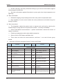
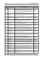
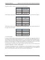
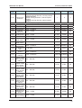
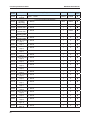
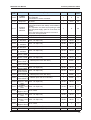
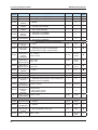
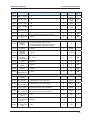
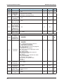
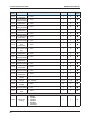
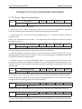
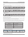
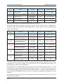
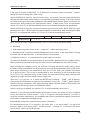
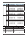
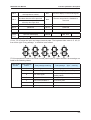
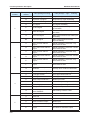
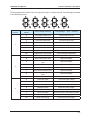
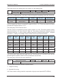
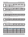
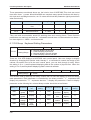
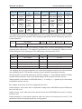
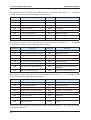
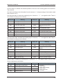
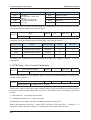
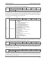
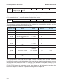
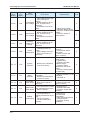
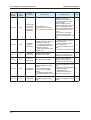
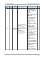
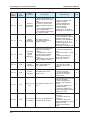
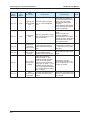
NICE3000 User Manual
Function
Code
Function parameters tables
Min. Unit
Default
Modification
0~65535
1
0
★
0~65535
1
0
★
0~65535
1
0
★
0~65535
1
0
★
0~65535
1
0
★
0~65535
1
0
★
0~65535
1
0
★
0~65535
1
0
★
0~65535
1
0
★
0~65535
1
0
★
0~65535
1
0
★
0~65535
1
0
★
0~65535
1
0
★
0~65535
1
0
★
0~65535
1
0
★
0~65535
1
0
★
0~65535
1
0
★
0~65535
1
0
★
0~65535
1
0
★
0~65535
1
0
★
0~65535
1
0
★
0~65535
1
0
★
0~65535
1
0
★
0~65535
1
0
★
0~65535
1
0
★
0~65535
1
0
★
0~65535
1
0
★
Name
bit of floor
F4-26 Highhigh
11
bit of floor
F4-27 Lowhigh
11
bit of floor
F4-28 Highhigh
12
Low
bit
of
floor
F4-29
high 12
bit of floor
F4-30 Highhigh
13
bit of floor
F4-31 Lowhigh
13
High
bit
of
floor
F4-32
high 14
bit of floor
F4-33 Lowhigh
14
bit of floor
F4-34 Highhigh
15
Low
bit
of
floor
F4-35
high 15
bit of floor
F4-36 Highhigh
16
bit of floor
F4-37 Lowhigh
16
High
bit
of
floor
F4-38
high 17
bit of floor
F4-39 Lowhigh
17
bit of floor
F4-40 Highhigh
18
Low
bit
of
floor
F4-41
high18
bit of floor
F4-42 Highhigh
19
bit of floor
F4-43 Lowhigh
19
High
bit
of
floor
F4-44
high 20
bit of floor
F4-45 Lowhigh
20
bit of floor
F4-46 Highhigh
21
Low
bit
of
floor
F4-47
high 21
bit of floor
F4-48 Highhigh
22
bit of floor
F4-49 Lowhigh
22
High
bit
of
floor
F4-50
high 23
bit of floor
F4-51 Lowhigh
23
bit of floor
F4-52 Highhigh
24
Setting Range
87
Function parameters tables
Min. Unit
Default
Modification
0~65535
1
0
★
0~65535
1
0
★
0~65535
1
0
★
0~65535
1
0
★
0~65535
1
0
★
0~65535
1
0
★
0~65535
1
0
★
0~65535
1
0
★
0~65535
1
0
★
0~65535
1
0
★
0~65535
1
0
★
0~65535
1
0
★
0~65535
1
0
★
0~65535
0~65535
F5 Terminal Function Parameters
1
1
0
0
*
*
1
3s
★
Function
Code
Name
F4-53
F4-66
F4-67
Low bit of floor
high 24
High bit of floor
high 25
Low bit of floor
high 25
High bit of floor
high 26
Low bit of floor
high 26
High bit of floor
high 27
Low bit of floor
high 27
High bit of floor
high 28
Low bit of floor
high 28
High bit of floor
high 29
Low bit of floor
high 29
High bit of floor
high 30
Low bit of floor
high 30
reserved
reserved
F5-00
ATT/Normal
switching time 3~200s
F4-54
F4-55
F4-56
F4-57
F4-58
F4-59
F4-60
F4-61
F4-62
F4-63
F4-64
F4-65
88
NICE3000 User Manual
Setting Range
NICE3000 User Manual
Function
Code
F5-01
F5-02
F5-03
F5-04
F5-05
F5-06
F5-07
F5-08
F5-09
F5-10
F5-11
F5-12
F5-13
F5-14
F5-15
F5-16
F5-17
F5-18
F5-19
F5-20
F5-21
F5-22
F5-23
F5-24
Name
Function parameters tables
Setting Range
Select function 00:No function
input of up leveling
of terminal X1 01:N.O.
02:N.O. input of down leveling
03:N.O.
input of door zone
Select function
input of Safety circuit feedback
of terminal X2 04:N.O.
05:N.O. input of Lock circuit feedback
Select function 06:N.O. input of running output feedback
of terminal X3 07:N.O. input of brake output feedback
signal
Select function 08:N.O. input of inspection signal
of terminal X4 09:N.O. input of inspection up
10:N.O. input of inspection down
Select function 11:N.O. input of fire signal
of terminal X5 12:N.O. input of upper limit signal
input of lower limit signal
Select function 13:N.O.
14:N.O. input of over loading
of terminal X6 15:N.O. input of full load
Select function 16:N.O. input of NO.1 up force reducer
input of NO. 1 down force reducer
of terminal X7 17:N.O.
18:N.O. input of NO.2 up force reducer
Select function 19:N.O. input of NO. 2 down force reducer
of terminal X8 20:N.O. input of NO.3 up force reducer
21:N.O. input of NO. 3 down force reducer
Select function 22:advanced door-opening module output
of terminal X9 feedback N/O input
23: N.O. input of firemen opening and
Select function closing
of terminal X10 24:N.O. input of door motor light-beam
Select function curtain1
25:N.O. input of door motor light-beam
of terminal X11 curtain2
Select function 26:N.O. input of brake output feedback 2
N.O. input of UPS
of terminal X12 27:Valid
28:N.O. input of lift-locking
29
:
N.O.
input
2 of safety signal
Select function
of terminal X13 30 : N.O. input of synchronous motor U,V,W
jump-out feedback
Select function 31 : N.O. input of door lock circuit2 feedback
of terminal X14 33:N.C. input of up leveling
34:N.C. input of down leveling
Select function 35:N.C. input of door zone
of terminal X15 36:N.C. input of Safety circuit feedback
input of Lock circuit feedback
Select function 37: N.C.input
of running output feedback
of terminal X16 38:N.C.
39: N.C. input of brake contactor feedback
Select function signal
of terminal X17 40:N.C. input of inspection signal
41:N.C. input of inspection up
Select function 42:N.C. input of inspection down
of terminal X18 43:N.C. input of fire signal
44:N.C. input of upper limit signal
Select function 45:N.C. input of lower limit signal
of terminal X19 46:N.C. input of over loading
47:N.C. input of full loading
Select function 48:N.C. input of NO.1 up forced deceleration
of terminal X20 49:N.C. input of NO. 1 down forced
Select function deceleration
input of NO.2 up forced deceleration
of terminal X21 50:N.C.
51:N.C. input of NO. 2 down forced
deceleration
Select function
of terminal X22 52:N.C. input of NO.3 up forced deceleration
53:N.C. input of NO. 3 down forced
deceleration
Select function 54:N.C. input of advanced door-opening
feedback
of terminal X23 module
55: N.C. input of firemen opening and closing
56:N.C. input of door motor light-beam
curtain1
57:N.C. input of door motor light-beam
curtain2
58:N.C. input of brake output feedback2
Select function 59:Valid N.C. input of UPS
of terminal X24 60 : N.C. input of lift-locking signal
61 : N.C. input 2 of safety signal
62 : N.C. input of synchronous motor U,V,W
jump-out feedback
63 : N.C. input of door lock circuit 2 feedback
Min. Unit
Default
Modification
1
33
★
1
35
★
1
34
★
1
04
★
1
05
★
1
38
★
1
39
★
1
22
★
1
40
★
1
09
★
1
10
★
1
44
★
1
45
★
1
48
★
1
49
★
1
50
★
1
51
★
1
00
★
1
00
★
1
00
★
1
00
★
1
00
★
1
00
★
1
00
★
89
Function parameters tables
Function
Code
F5-25
F5-26
F5-27
F5-28
F5-29
F5-30
F5-31
F5-32
F5-33
F5-34
F5-36
F6-00
F6-01
F6-02
F6-03
F6-04
F6-05
F6-06
F6-07
F6-08
90
Name
Car top board
input type
selection
Select function
of terminal Y1
Select function
of terminal Y2
Select function
of terminal Y3
Select function
of terminal Y4
Select function
of terminal Y5
NICE3000 User Manual
Setting Range
0~255
0:No function
1:Run contactor output
2:Brake contactor output
3:advanced door-opening module output
4:Fire arrival landing signal feedback
5:Door motor 1 open
6:Door motor 1 close
7:Door motor 2 open.
8:Door motor 2 close
9:Brake, run contactor normal
10:Failure state
11:Run monitor
12:Synchronous motor U,V,W jump-out
output
13:Power failure emergency running
switching automatically
Select function 14:System normal
of terminal Y6 15: Emergency buzzer output
16: Brake forced output
17: elevator up running mark
18: illustration and fan output
Communication Bit 0-bit11 hall call communication state
state display Bit12-bit15 inside call communication state
Bit 4: cancel the arrival gong at night
Bit 5: input function 25/57 for the mmotor
overheat input or earthquake detection
Bit 6: add 1 more time doo-lock break when
Program control the inspection to normal
Bit 7: no error display on the small keypad
select
Bit 8: remove the door-open call when dooropen limit
Bit 9: elevator stop when the brake feedback
is abnormal
Terminal state
display
0:car top panel input and analogue input is
Weighing input invalid
1:Car top panel switch input
selection
2:Car top panel analog input
3:Main control panel analog sampling.
F6 Lift Basic Parameters
The highest F6-01~31
landing
The lowest 1~F6-00
landing
Parking main F6-01~ F6-00
landing
Fire main
F6-01~F6-00
landing
Lift lock main F6-01~F6-00
landing
service floor 1 0~65535 (from 1st to 16th floor)
service floor 2 0~65535 (from 17th to 31st floor)
Group control 1~8
number
Lift number 1~8
Min. Unit
Default
Modification
1
64
★
1
1
★
1
2
★
1
3
★
1
4
★
1
0
★
1
0
★
●
1
0
●
1
2
★
1
9
★
1
1
★
1
1
★
1
1
★
1
1
★
1
1
65535
65535
★
★
1
1
★
1
1
★
NICE3000 User Manual
Function
Code
Name
F6-09
Parallel
selection
Function parameters tables
Setting Range
Bit0:separate stay function
Bit1: reserved
Bit2:Parallel in monitor contactor
sensor 10~50ms
F6-10 Leveling
delay time
Bit4: stop 300 ms current bias mode
Bit5:synchronous motor startup current detect
function
Elevator
Bit7: inspection non-door zone opening is valid
F6-11
function
Bit8:
first power-apply, open for once when it is
selection
normal
Bit10: reversal-leveling buzzer is not sound
Bit13: E53 error auto reset
F6-12
VIP floor
0- highest floor (F6-00)
F6-13 Security floor F6-01~F6-00
F6-14 down-collective
1 start time 00.00~23.59(hr.min.)
F6-15 down-collective
1 end time 00.00~23.59(hr.min.)
F6-16 down-collective
2 start time 00.00~23.59(hr.min.)
down-collective
F6-17
2 end time 00.00~23.59(hr.min.)
Time-sharing 00.00~23.59(hr.min.)
F6-18 service
1 start
Time-sharing
F6-19 service 1 end 00.00~23.59(hr.min.)
Time-sharing 0~65535 (from 1st to 16th floor)
F6-20 service
1 floor 1
Time-sharing 0~65535 (from 17th to 31 st floor)
F6-21 service
1 floor 2
Time-sharing
F6-22 service 2 start 00.00~23.59(hr.min.)
Time-sharing 00.00~23.59(hr.min.)
F6-23 service
2 end
Time-sharing 0~65535 (from 1st to 16th floor)
F6-24 service
2 floor 1
Time-sharing
F6-25 service 2 floor 2 0~65535 (from 17th to 31 st floor)
Parallel
F6-26 fastigium 1 start 00.00~23.59(hr.min.)
time
Parallel
F6-27 fastigium 1 end 00.00~23.59(hr.min.)
time
Parallel
F6-28 fastigium
floor 1 F6-01~F6-00
Parallel
F6-29 fastigium 2 start 00.00~23.59(hr.min.)
time
Parallel
F6-30 fastigium 2 end 00.00~23.59(hr.min.)
time
Parallel
F6-31 fastigium floor 2 F6-01~F6-00
F7 Testing Function Parameters
F7-00
Test floor 1 0~the highest floor (F6-00)
Min. Unit
Default
Modification
1
0
★
1
14ms
★
1
0
★
1
1
0
1
★
☆
00.01
00.00
☆
00.01
00.00
☆
00.01
00.00
☆
00.01
00.00
☆
00.01
00.00
☆
00.01
00.00
☆
1
65535
☆
1
65535
☆
00.01
00.00
☆
00.01
00.00
☆
1
65535
☆
1
65535
☆
00.01
00.00
☆
00.01
00.00
☆
1
1
☆
00.01
00.00
☆
00.01
00.00
☆
1
1
☆
1
0
☆
91
Function parameters tables
Function
Code
F7-01
F7-02
F7-03
F7-04
F7-05
F7-06
F7-07
Min. Unit
Default
0~the highest floor (F6-00)
1
1
0
0
Modification
☆
☆
Name
Test floor 2
Test floor 3
Test times at
random
Landing call
enable
Door open
enable
Overload
function
selection
Limit enable
NICE3000 User Manual
Setting Range
0~60000
1
0
☆
0:Landing call allowable;
1:Landing call forbidden
0:Door open allow
1:Door open forbidden
1
0
☆
1
0
☆
0:Overload run forbidden
1:Overload run allowable
1
0
☆
0:End switch availability;
1:End switch invalidation
F8 Reinforce Function Parameters
1
0
☆
1%
0%
★
1
0
★
0.1%
50.0%
15.0%
★
0.01
0.60
0.50
★
0.01
0.60
0.60
★
1
0
●
1
1
0
100
★
★
1
0
☆
auto- 0~100%
F8-00 Weighing
tuning
is invalid
Pre-torque 0:Pre-torque
1:weighing pre-torque compensation
F8-01
selection
2: automatic pre-torque compensation
Pre-torque bias,
Zero servo 0.0~100.0%
0.20%~50.0%
current
coefficient
Drive gain, 0.00~2.00
F8-03
Zero servo
speed loop KP 0.00~1.00
F8-02
Brake gain
Zero servo
speed loop TI
Car load at
F8-05
present
F8-06 Car no load set
F8-07 Car full load set
F8-04
F8-08
F8-09
F8-10
F8-11
F9-00
F9-01
F9-02
F9-03
92
0.00~2.00
0.00~2.00
0~1023
0~1023
0~1023
function is forbidden;
Anti-nuisance 0:This
1:Allowable (This function can be used with
function
weighing sensor available.)
Power failure
emergency 0.000~0.100m/s
rescue speed
Power failure 0: no running
emergency 1: UPS power running
rescue
2: 48V battery power
selection
Stopping torque 0.200~1.500s
output delay
F9 Time Parameters
Free return 0~240min
main floor time
Fan and light 0~240min
closed time
Longest interval
time of floor 0~45s (invalidation under 3s)
running
Clock: year
2000~2100
0.001m/s 0.050m/s
☆
1
0
☆
0.001
0.200
☆
1min
10min
☆
1min
2min
☆
1s
45s
★
1
Current
time
☆
NICE3000 User Manual
Function
Code
Function parameters tables
Name
Setting Range
Min. Unit
Default
1
Modification
F9-05
Clock: day
1~31
1
F9-06
Clock: hour
0~23
1
Clock: minute 0~59
1
Current
time
Current
time
Current
time
Current
time
0~65535hr.
1
0
●
0~9999
Note: 1 means actual 10000 run times
1
0
●
0~9999
1
0
●
1
0
☆
1
65535
☆
1
65535
☆
0.1°
0.0°
●
1
0
●
1
0
●
1
0
●
1℃
0
●
1
1
★
1
65535
☆
1
65535
☆
1
65535
☆
1
65535
☆
1s
10s
☆
1ms
0
☆
1s
15s
☆
F9-04
F9-07
Clock: month 1~12
F9-09 Accumulative
working time
high
F9-11 Run times
bit
low
F9-12 Run times
bit
FA-00
FA-01
FA-02
FA-03
FA-04
FA-05
FA-06
FA-07
FB-00
FB-02
FB-03
FB-04
FB-05
FB-06
FB-07
FB-08
FA Keyboard Setting Parameters
0:
Reversal
physics floor
Small keyboard 1:Positive display,
display, physics floor
display
2:Reversal
display,
external call data
selection
3:Positive display, external call data
Running display 1~65535
selection
Stopping
display
1~65535
selection
Pulse wheel
encoder
0.0~360.0°
currently angle
Software edition 0~65535
1(FK)
Software edition 0~65535
2(ZK)
Software edition 0~65535
3(DSP)
Radiator
temperature 0~100℃
FB Door Function Parameters
door machine 1~2
number
Door machine1 0~65535(from 1st to 16th floor)
service floor 1
Door machine1 0~65535(from 17th to 31st floor)
service floor2
Door machine2 0~65535(from 1st to 16th floor)only valid
service floor1 when there are two door machines
Door machine2 0~65535(from 17th to 31st floor) only valid
service floor2 when there are two door machines
Time protection
for opening the 5~99s
door
Arrival gong
output delayed- 0~1000ms
time
Time protection
for closing the 5~99s
door
☆
☆
☆
☆
93
Function parameters tables
Function
Code
FB-09
FB-10
FB-11
FB-12
FB-13
FB-14
FC-00
FC-01
FC-02
FC-03
FC-04
FC-05
94
Name
NICE3000 User Manual
Setting Range
Door open/
close times 0~20
Run main
open the door normally
landing door 0:
1: waiting for opening the door
state
Time keeping
for hall call door 1~30s
opening
Time keeping
for internal call 1~30s
door opening
Time keeping
for opening at
main landing
(main landing is 1~30s
used including
Single Lift,
Group Control,
and Lock Lift)
Delay time for 10~1000s
open keeping
FC Protect Function Parameters
Earth short
circuit
0:Forbidden;
protection
detection after 1:Allowable
power on
Bit0:Overload protection selection
0:Forbidden
1:Allowable
Bit1:Output phase-failure selection
0:Phase-failure protection
1:Phase-failure unprotected
Bit3: E053 add door-close limit judgment
0:no new method
1:old method + old method
Bit4:
door-closing limit judge light curtain
Protection
0:no re-opening
selection
1:re-open the door
Bit5: DSP communication judgment
0:wire broken check
1:no check
Bit6: new method for parallel door block
0: use mew method
1: resume to 745 program
Bit7:reveling over-speed check
0:check
1:no check
Overload
protection
0.50~10.00
coefficient
Overload
pre-warning 50~100%
coefficient
0:Means that the system forbidden autoError selffunction;
resetting times resetting
0~10
Reset interval 2~20s
time
Min. Unit
Default
Modification
1
0
☆
1
0
1s
5s
☆
1s
3s
☆
1s
10s
☆
1s
30s
☆
1
1
★
1
1
☆
0.01
1.00
☆
1%
80%
☆
1
0
★
1s
5s
★
NICE3000 User Manual
Function
Code
FC-06
FC-07
FC-08
FC-09
Name
Function parameters tables
Setting Range
0~3199
Note: The first two figures mean the floor’s
number, and the last two mean the error code.
e.g. error 30 occurs in Floor1(the elevator’s
position is abnormal), the error information
displays 0130.
0: No error
1: Inverse unit protection
2: Over current accelerated
3: Over current decelerated
4: Over current constant
5: Over voltage accelerated
6: Over voltage decelerated
7: Over voltage constant
8: Controller power fault
9: Under voltage fault
10:Controller overload
11: Motor overload
12: Input side phase loss
13: Output side phase loss
14: Module overheated
15: Reserved
16: Reserved
17:Contactor fault
18: Current detection fault
19: Motor tuning fault
20: Encoder fault
21: Synchronous motor encoder wiring error
Leveling inductor signal is abnormal
The first error 22:
Short circuit fault to ground
information 23:
24:Reserved
25: Data storage error
26~28: Reserved
29: Synchronous self-locking contactor
feedback is deviant
30: Lift position is deviant
31: DPRAM is deviant
32: CPU is deviant
33: Lift over speed error
34: Logic fault
35: shaft auto-tuning date is deviant
36: Contact feedback is deviant
37: Brake feedback is deviant
38: Controller encode signal is deviant
39: Motor overheated
40: Lift running condition is not satisfied
41: Safety circuit cut
42: Door lock cut when running
43: Upper limit signal cut when running
44: Lower limit signal cut when running
45: Up/Down force reducer switch cut
46: Re-leveling is deviant
47: Lock contactor is deviant
48: Door open fault
49: Door close fault
50: Group control communication fault
51: Inside call communication fault
52: Outside call communication fault
53: Lock jump fault
The first error 0~1231
month and day
The second
error
0~3199
information
The second
error month and 0~1231
day
Min. Unit
Default
Modification
1
0
●
1
0
●
1
0
●
1
0
●
95
Function parameters tables
Function
Code
FC-10
FC-11
FC-12
FC-13
FC-14
FC-15
FC-16
FC-17
FC-18
FC-19
FC-20
FC-21
FC-22
FC-23
FC-24
FC-25
FC -26
FC -27
FC -28
FC-29
FC-30
FC-31
FD-00
96
Name
NICE3000 User Manual
Setting Range
The third error 0~3199
information
The third error 0~1231
month and day
The fourth error 0~3199
information
The fourth error 0~1231
month and day
The fifth error 0~3199
information
The fifth error 0~1231
month and day
The sixth error 0~3199
information
The sixth error 0~1231
month and day
The seventh
error
0~3199
information
The seventh
error month and 0~1231
day
The eighth error 0~3199
information
The eighth error 0~1231
month and day
The ninth error 0~3199
information
The ninth error 0~1231
month and day
The tenth error 0~3199
information
The tenth error 0~1231
month and day
The last error 0~3199
information
Latest error 0.000~3.000m/s
speed
Latest error 0.0~999.9A
current
Latest error bus 0~999V
voltage
Latest error 0~1231
month and day
Latest error 0~2359
time
FD Communication Parameters
0:300bps
1:600bps
2:1200bps
3:2400bps
Baud rate
4:4800bps
setting
5:9600bps
6:19200bps
7:38400bps
Min. Unit
Default
Modification
1
0
●
1
0
●
1
0
●
1
0
●
1
0
●
1
0
●
1
0
●
1
0
●
1
0
●
1
0
●
1
0
●
1
0
●
1
0
●
1
0
●
1
0
●
1
0
●
1
1
●
0.001m/s
0.000
●
0.1A
0.0
●
1V
0
●
1
0
●
1
0
●
1
5
★
NICE3000 User Manual
Function
Code
FD-01
FD-02
FD-03
FD-04
FE-00
Name
Function parameters tables
Setting Range
0: No check-out: Data format<8,N,2>
1: Even check-out: Data format<8,E,1>
2: Odd check-out: Data format<8,0,1>
Local address 0~127,0:Broadcasting address
Responding 0~20ms
delay
Communication 0.0~60.0s ,0.0s:invalidation
delay time
FE Lift Function Setting Parameters
0:Fulll selective
Collective
selective mode 1:Down selective
2:Up selective
Data format
Min. Unit
Default
Modification
1
0
★
1
1
★
1ms
10ms
★
0.1s
0.0s
★
1
0
☆
97
Function parameters tables
Function
Code
Name
NICE3000 User Manual
Setting Range
display of
FE-01 Hall floor
1
Hall
display of
FE-02
floor 2
display of
FE-03 Hall floor
3
display of
FE-04 Hall floor
4
display of
FE-05 Hall floor
5
display of
FE-06 Hall floor
6
display of
FE-07 Hall floor
7
display of
FE-08 Hall floor
8
display of
FE-09 Hall floor
9
display of
FE-10 Hallfloor
10
0000~1999
Hall
display of Note: the first two numbers represent tens digit
FE-11
floor 11
display code of the floor; the last two represent
display of first rank code. The first rank codes are as
FE-12 Hallfloor
12
follows:
display of 00:display“0”
FE-13 Hallfloor
13
01:display“1”
display of 02:display“2”
FE-14 Hallfloor
03:display“3”
14
display of 04:display“4”
FE-15 Hallfloor
05:display“5”
15
display of 06:display“6”
FE-16 Hallfloor
07:display“7”
16
display of 08:display“8”
FE-17 Hallfloor
09:display“9”
17
10:display” A”
Hall
display
of
FE-18
11:display“B”
floor 18
12:display“G”
display of 13:display“H”
FE-19 Hallfloor
19
14:display“L”
display of 15:display“M”
FE-20 Hallfloor
20
16:display“P”
display of 17:display“R”
FE-21 Hallfloor
21
18:display“-”
display of 19:no display
FE-22 Hallfloor
22
20: display”12”
display of 21: display”13”
FE-23 Hallfloor
23
22: display”23”
display of
FE-24 Hallfloor
24
display of
FE-25 Hallfloor
25
display of
FE-26 Hallfloor
26
display of
FE-27 Hallfloor
27
display of
FE-28 Hallfloor
28
display of
FE-29 Hallfloor
29
display of
FE-30 Hallfloor
30
Hall display of
floor 31
(double door
FE-31 plural
selection
hall call address
setting)
98
Min. Unit
Default
Modification
1
1901
☆
1
1902
☆
1
1903
☆
1
1904
☆
1
1905
☆
1
1906
☆
1
1907
☆
1
1908
☆
1
1909
☆
1
0100
☆
1
0101
☆
1
0102
☆
1
0103
☆
1
0104
☆
1
0105
☆
1
0106
☆
1
0107
☆
1
0108
☆
1
0109
☆
1
0200
☆
1
0201
☆
1
0202
☆
1
0203
☆
1
0204
☆
1
0205
☆
1
0206
☆
1
0207
☆
1
0208
☆
1
0209
☆
1
0300
☆
1
0301
☆
NICE3000 User Manual
Function parameters tables
Function
Code
Name
Setting Range
Min. Unit
Default
Modification
FE-32
Lift factory
function
selection1
0~65535
Selected by bit, the function is valid if the bit is
1, details referring to chapter 6.
1
35843
★
FE-33
Lift factory
function
selection2
Selected by bit, the function is valid if the bit is
1, details referring to chapter 6.
1
32
★
1
0
☆
1
0
★
1
0
★
FP User Parameters
0~65535
FP-00 User password 0:indicates no password
Parameter 0:Invalidation
FP-01
1:Recover the default Parameter
renewal
2:Clear memory
User setting 0:Invalidation
FP-02
inspect
1:valid
99
Function parameters tables
100
NICE3000 User Manual
6
Function parameter description
NICE3000 User Manual
Chapter 6 Function parameter description
6.1 F0 Group Basic Function Group
F0-00
Control mode
Setting Range
Default
1
Min. Unit
1
0、1
Select the control mode of the system.
0:Open-loop vector. Speed sensorless vector control. It is mainly applicable for low speed
running in adjusting and fault judging in maintaining of asynchronous motor.
1:Close-loop vector. Vector control with speed sensor. It’s used for distance control in
normal running.
NOTE: The synchronous motor doesn’t use open-loop vector. Please tune the motor before
lift inspection running.
F0-01
Command source selection
Setting Range
Default
1
Min. Unit
1
0、1
It can set the lift running type with travel mode and speed command.
0:Operating panel command channel. Press the buttons such as RUN, STOP on the
operating panel to perform the command control. The traveling speed is decided by parameter
F0-02(Panel controller running speed).
1:Distance control. It is used for NICE3000. When it’s in inspection running the lift run with
the speed according to the setting of parameter F3-1; it enables direct parking according to the
distances from the current land to the target land while calculating running speed and curves
automatically.
F0-02
Operating panel speed
Setting Range
Default
0.050m/s
Min. Unit
0.001m/s
0.050~F0-04
This function is only used when function code is F0-01=0(operating panel command channel).
It sets the default of speed when lift is used by operating panel. You can modify this code to
change speed of operating panel control when traveling.
F0-03
Lift Max. running speed
Setting Range
Default
1.600 m/s
Min. Unit
0.001m/s
0.250~F0-04
It can set the Max. Speed when the lift is running and it should below rated speed of the lift.
F0-04
Lift rated speed
Setting Range
Default
1.600 m/s
Min. Unit
0.001m/s
0.250~4.000m/s
It means rated speed of nameplate of lift. This function parameter is decided by the machine
102
NICE3000 User Manual
Function parameter description
and motor of the lift. The parameter F0-03 means the actual speed within the speed range of
F0-04.
For example: One lift rated speed is 1.750 m/s, but the actual Max.speed is 1.720 m/s. So
F0-03 = 1.720 m/s; F0-04 = 1.750 m/s.
F0-05
Lift rated load
Setting Range
Default
1000kg
Min. Unit
1kg
300~9999kg
It can set the rated load of lift. This code is used for anti-nuisance function.
F0-06
Max. frequency
Setting Range
Default
50.00Hz
Min. Unit
0.01Hz
20.00~99.00Hz
It can set Max. Frequency of system output and the frequency must be higher than rated
frequency of the motor.
F0-07
Carrier frequency
Setting Range
Default
6kHz
Min. Unit
0.1kHz
0.5~16.0kHz
The magnitude of carry frequency ties up the noise of motor running. The carry frequency is
generally set upward 6 kHz to manage to travel without noise. To the best of noise allowing
range, reduce the carry frequency
When the carrier frequency is low, the output current higher-harmonic component increases,
the consumption and temperature rise of the motor increase as well.
When the carrier frequency is high, the motor consumption declines and the motor temperature
rise reduces, but the consumption, temperature rise and interference of the system increase.
To regulate the carrier frequency will exert influences on the following performances:
Carrier Frequency
Low~High
Motor noise
Large~Small
Output Current Wave Form
Bad~Good
Motor Temperature Rise
High~Low
System Temperature Rise
Low~High
Leakage Current
Small~Large
External Radiation Interference
Small~Large
6.2 F1 Group Motor Parameters
Function code
F1-00
Name
Selection of
encoder’s type
Default
Min. Unit
Setting Range
1model
1
0: SIN/COS
1:UVW
The parameter is invalidation for the asynchronous motor. For synchronous motor UVW selects
1, ERN1387 SIN/COS encoder selects 0.
103
Function parameter description
Function
code
Name
NICE3000 User Manual
Default
Min. Unit
Setting Range
Depending on
the model
0.1kW
1.1~75.0kW
F1-01
Rated power
F1-02
Rated voltage
380V
1V
0~440V
Rated current
Depending on
the model
0.01A
0.00~655.00A
F1-03
F1-04
Rated frequency
50.00Hz
0.01Hz
0.00~99.00Hz
F1-05
Rated rotation speed
1460rpm
1rpm
0~3000rpm
Please set according to the nameplate parameters of the motor.
The system has motor parameter auto-tuning function. Only when the motor’s parameter is
setting correctly can the system complete parameter tuning function correctly to fulfill good
vector control function.
Function
code
F1-06
F1-07
F1-08
F1-09
Name
Default
Min. Unit
Setting Range
Stator resistance
(Asynchronous motor)
Depending on
the model
0.001Ω
0.000~30.000Ω
Encoder initialized angle
(Synchronous motor)
Depending on
the mode
0.1°
0~359.9°
Rotor
resistance(asynchronous)
Current angle(sync)
Depending on
the model
0.1
0.001Ω
0.000~30.000Ω
Leakage inductance
(Asynchronous motor)
Depending on
the model
0.01mH
0.00~300.00mH
Wiring connection
(Synchronous motor)
Depending on
the model
1
0~15
Mutual inductance
Depending on
the model
0.1mH
0.1~3000.0mH
0.0
0.1
0-40
Depending on
the model
0.01A
0.01~300.00A
0.0
0.1
0-31
ADC sampling delay
function (sync)
No-load current
F1-10
Selection check of
encoder’s signal
To ensure system performance, please set according to the system standard of the motor
arrangement. If the motor power is a lot different from the standard motor power, the
performance of system control will decline.
The parameter F1-06 means different meaning when used in different motors. When it’s used
in asynchronous motor, it means the stator resistance. When it’s used in synchronous motor,
it means the encoder initialized angle. No matter which motor to be used in, this parameter can
be created after NICE3000 tuning. And users can modify this parameter according to actual
condition.
If the automatic tuning of the motor is completed normally, the setup values in F1-F6 to F1-F10
will update automatically.
104
NICE3000 User Manual
Function parameter description
If the type of encoder is SIN/COS, F1-10 parameter is selection check of encoder’s signal,
setting as 1 before tuning and 2 after tuning.
When NICE3000 is used for asynchronous motor: the system can gain these parameters
through with-load tuning (static tuning) or no-load tuning (complete tuning). If the motor cannot
be tuned on the spot, the known parameters of the same kind of motors can be a reference for
manual input. After modifying the asynchronous motor’s rated power F1-01, the parameter
values in F1-06 to F1-10 will automatically recover to the default standard motor parameters.
When NICE3000 is used for permanent-magnet synchronous motor: NICE 3000 can gain
parameters F1-06, F1-08 through with-load tuning and no-load tuning. After modifying the rated
power F1-01, the parameter values in F1-06 to F1-10 will not automatically recover.
F1-11
Tuning selection
Setting Range
Default
0
Min. Unit
1
0、1、2、3
Note: The correct motor rated parameters (F1-01~F1-05) must be set before tuning.
0:No tuning.
1:With-load tuning while in use, motor’s load won’t affect the tuning result.
2:No-load tuning. It requires complete separation from the motor to the load. While in tuning
the motor will run and the motor’s load will affect the tuning result.
3: shaft auto-tuning: It’s in need before the motor begins to run fast.
To ensure the dynamic control performance of the controller, please select the complete tuning.
When performing the complete tuning, the motor must be separated from the load (no-load).
After selecting the complete tuning, the controller will firstly perform the static tuning. When
the static tuning is completed, the asynchronous motor will be accelerated to 80% of the motor
rated power according to the acceleration time set in F3-02. And it will maintain this status
for a period of time. Then it will be decelerated to zero according to the deceleration time
set in F3-05. The complete tuning is then ended; the synchronous motor step positively and
negatively to judge the pulse wheel encoder origin point.
After the F1-11 is set as 1 or 2, press the ENTER key to display “TUNE” that is flashing.
Then press the RUN button to perform the parameter tuning, the “TUNE” stops flashing.
After the tuning is completed, it will display the stop status interface. And the STOP button can
be pressed in the tuning process to suspend the tuning.
After the tuning is completed, the values in F1-11 will automatically recover as 0.
Attention: if using the permanent-magnet synchronous motor, the system must be complete
tuning. Because the system doesn’t only to recognize related parameters, but also to
recognize encoder original point. It is forbidden that travel the permanent-magnet synchronous
motor before complete the complete tuning.
Automatically tuning step of asynchronous motor is following:
For asynchronous motor, F1-11 selects 1, the motor won’t run and it needn’t to get rid off
the rope. While in auto-tuning, there’s noise of motor’s current. F1-11 selects 2, the motor
will run and it need to get rid off the rope.
105
Function parameter description
NICE3000 User Manual
First, set F0-01 as 0: the control mode selection is the operating panel command channel.
Set F1-00 as 0 by actual motor types: asynchronous motor. Then set F1-01、F1-02、F1-03、
F1-04、F1-05 according to the nameplate parameters of motor.
If the motor can be separated from load, the parameter F1-11 selects 2(motor no-load tuning).
Then press RUN of the operating panel and the motor can automatically run. The control
automatically counts these parameters as follows: F1-06 (stator resistance), F1-07 (rotor
resistance), F1-08 (leakage inductance), F1-09 (mutual inductance) and F1-10 (no-load
excitation current). The motor tuning is then over. If the system appears over current, please
increase the parameter F1-10, but don’t exceed 20%.
If the motor can’t be separated from load, the parameter F1-11 selects 1(motor with-load
tuning).Then press RUN of the operating panel and the motor can automatically tune. The
controller only automatically counts three parameters: stator resistance, rotor resistance, and
leakage inductance. It automatically counts mutual inductance and no-load current of motor as
well.
106
NICE3000 User Manual
Function parameter description
F0-01=0
Set as operation panel control
F1-01、F1-02、F1-03、F1-04、F1-05
set according to the nameplate parameters of the motor
F0-01=0 Operating panel command channel
F1-11=1or2
(1:Static tuning .
2:Complete tuning , must separate the load from motor)
note:thedisplay TUNE that is flashing ,make sure the output
circuit is looped,Then press the RUN button to perform the
parameter tuning .
Static tuning
Complete tuning ,the motor is actionless,
but engender electromagnetism noises 。
Then we can get the Parameter:
F1-06、F1-07、F1-08.
F1-09、F1-10 is automatically count
Complete tuning
Complete tuning .Motor will running about
one min.we can get the paremeter:
F1-06、F1-07、F1-08、F1-09、F1-10。
After tuning,recover the paremeter F0-01=1
Fig 6-1 Asynchronous motor tuning flow chart
Automatically tuning step of permanent-magnet synchronous motor is following:
1)
First, set F0-01 as 0: the control mode selects the operating panel command channel.
2)
Set F1-00 as 0 by actual motor type: synchronous motor. Then set F1-01、F1-02、
F1-03、F1-04、F1-05 according to the nameplate parameters of motor.
3)
Completely separate the motor from the load (rope), the parameter F1-11 selects
2(complete tuning). Then press RUN of the operation panel and the motor can
automatically run. The controller automatically counts the F1-06 encoder initialized angle.
The motor tuning is then over. Operate the tuning more than 3 times, then compare F1-06
encoder initialized angle already gained, make sure the error is within the range of ±5°.
107
Function parameter description
4)
NICE3000 User Manual
After tuning, set F0-02=0.5 m/s, and press RUN .Check if the motor running is right or
not. If motor isn’t running right, please repeat step 1, 2, 3 after transposing direction of
encode signal.
F0-01=0(No load tunning)
Or (with load tuning )
Recover the setting parameter of terminal running
command way state: F0-01=1
Recover the iron rope’s position
F1-00=1
Select as synchronous motor
Set parameters according to the motor’s nameplate: F101, F1-02, F1-03, F1-04, F1-05
And encoder’s pulse number: F1-12
F1-11=2
Lift the car cage to make the motor off
the load
F1-11=1
After the tuning, set F0-02=10.00Hz. Press key
RUN, and check if the motor is running normally. If
not, please change the pulse wheel encoder’s
signal direction and start re-tuning.
In dynamic tuning, the motor is forward and reversal
running. Parameters of F1-06 pulse wheel encoder
magnet pole’s angle are gained through tuning.
Commend to recognize more than three times and it’s
correct if the error of F1-06 is between ±5°.
No load tunning,F0-01=0
Set as operation panel control
F1-11=2
Phenomenon: The indicator “tune” lights on the top of operation panel, making the output to the side circuit
through. Press key RUN, the operation panel’s indicator RU N lights, and then tuning begins
Fig 6-2 Adjusting flow chart of permanent-magnet synchronous motor
Before the first running, the magnet pole identification is necessary for the permanent-magnet
synchronous hoist motor, otherwise it can’t be normally used. After the change of motor
wiring, encoder and encoder wiring, it’s needed to re-recognize the pulse wheel encoder’s
position angle. Therefore, the motor wiring, PG card wiring must be the same when in
recognizing the magnet pole’s position and the motor normally running. In the identification
course, the motor will run, so you must assure that the synchronous hoist motor which is
recognized must be in no load state.
Before the identification, the parameters of F1 group motor’s nameplate must be inputted
correctly, including rated frequency, rated voltage, rated power, rated rotation speed, rated
current. And set the encoder’s pulse number (F1-12) correctly. Then set F1-11 as 2 and press
key “confirm”, the inverter will display “TUNE”. Press key RUN, the inverter begins to
recognize. The inverter will display “TUNE” all through the identification course. When the
“TUNE” disappears, the identification is then over.
The result of the identification is the encoder’s installation angle. It’s located in the F1-06
function, and can be checked and modified. The parameter modification is forbidden after the
position identification. Otherwise the inverter can’t run normally.
After the identification, F1-06, F1-08 are setting as motor control reference. Users needn’t
modify it. Otherwise the lift can’t run normally.
If alarming error E20 occurs in the encoder position’s identification course, please check
whether the PG card is correctly connected. The inverter adopts the vector control mode with
a transducer (assure parameter F0-00 is 1), and it must connect with PG card and encoder
correctly. Otherwise alarm E20 displaying on the panel to indicate encoder’s error.
108
NICE3000 User Manual
Function parameter description
If E21 alarms in the starting, check that whether the identification result parameters F1-06 and
F1-08 are correct t. If it’s ensured that the wiring of motor and PG card isn’t changed, you
can directly input the two data recorded after the first identification, or re-recognize the pulse
wheel encoder’s position angle.
Recommendation: Recognize the encoder’s position several times, compare with the data of
F1-06, if the error is without ±5°, which indicates errors exist in the encoder or wiring.
Running trial
After the encoder’s position identification, do the running trials with no load (the traction
machine with no iron wires) before the recovery. The mode of running trial is recommended to
adopt inspection up and down buttons, at the moment, deal with the safety circuit and door lock
circuit according to the system condition. In the running trial course, the following two points
need specially care:
If the direction of the traction machine is corresponding to the reality (Up and Down), if not,
it needs to adjust the NICE 3000 wiring outputting to the motor, re-recognize the encoder’s
position.
Whether the traction machine’s forward and reversal running are stable and no noise;
because of no load in the traction machine, the current will be extremely small and NICE 3000
displays the current lower than 1A.
After the confirmation of the two points, NICE 3000 have recorded the traction machine’s
encoder position correctly into F1-06 (Users can record it down for the later using), and it can
do the normal control. The following step is adjusting according to the lift’s normal adjusting
course. Due to the different features of synchronous motor and asynchronous motor, user can
reduce the speed loop P1 gain of F2 group when in use.
Note: After the lift is using normally, adjust the motor wiring and encoder wiring will both cause
the lift can’t be normally used.
The usually used parameters:
Shaft parameter auto-tuning is used to record the position of shaft’s opening and closing
(Including leveling switch and force reducer switch). Requirements are as follows:
Encoder and leveling feedback is normal; the switch of the shaft is installed well.
The lift is in the ground floor, forced deceleration switch operation.
The lift is in examination and can check running.
The lowest and highest floors are set correctly.
NICE 3000 is not in the error alarming state.
Note: shaft auto-tuning can also be realized by the small keyboards on the main control panel.
Two floor auto-tuning needs the lift run under the first leveling which means there’s one
leveling sensor under the leveling plate..
F1-12
Encoder pulse number per rotation
Setting Range
Default
1024
Min. Unit
1
0~10000
109
Function parameter description
NICE3000 User Manual
It can set the pulse number of each rotation of the encoder, according to the nameplate of
encode.
Note: it must set the encoder pulse number correctly when it’s in the closed loop vector
control. Otherwise it cannot work normally. If the asynchronous motor still cannot work normally
after the encoder pulse number set correctly, please exchange the connection line between the
phase A and B of the encoder. The encoder pulse number of permanent-magnet synchronous
motor must be set according to the UVW encoder, and the pulse number per rotation should be
set according to the encoder nameplate.
F1-13
Encode failure monitoring times
Setting Range
Default
3.0s
Min. Unit
0.1s
0.0~10.0s
It can set monitoring time when encode fault occurs. After lift starts running with speed of
nonzero, the system begins to receive signal of encoder every time of F1-13 setting. If there’s
none signal input, the system will show Err20 which means encoder failure.
6.3 F2 Group Vector Control Parameters
Function code
Name
Default
Min. Unit
Setting Range
F2-00
Proportional gain 1
of speed loop
40
1
0~100
F2-01
Integration time 1
of speed loop
0.60s
0.01s
0.01~10.00s
F2-02
Switching
frequency 1
2.00Hz
0.01Hz
0.00~F2-05
F2-03
Proportional gain 2
of speed loop
35
1
0~100
F2-04
Integration time 2
of speed loop
0.80s
0.01s
0.01~10.00s
F2-05
Switching
frequency 2
5.00Hz
0.01Hz
F2-02~F0-05
The parameters of F2-00 and F2-01 decide the dynamic response characteristic of the
frequency that is smaller than the switching frequency 1 (F2-02), while the parameters of F2-03
and F2-04 decide the dynamic response characteristic of the frequency that is larger than
the switching frequency 2 (F2-05). The dynamic response characteristic parameters of the
frequency between the switching frequency 1 and switching frequency 2 equal to the weighted
average value of two set of F2-00、F2-01 and F2-03、F2-04. As shown in Chart 6-2:
110
NICE3000 User Manual
Function parameter description
Fig 6-3 PI Parameters Schematic Diagram
It can regulate the speed dynamic response characteristic of the vector control by setting
the proportional coefficient and integrating time of the speed regulator. It can accelerate the
dynamic response of the speed loop by increasing the proportional gain or decreasing the
integrating time. Too large the proportional gain or too small the integrating time will cause the
system to vibrate.
The regulating methods are recommended as follows:
If the factory parameters cannot satisfy the requirements, conduct minor adjustment on the
basis of the factory parameters:
Enlarge the proportional gain first to prevent the system from vibrating, and then diminish the
integrating time to ensure that the system has fast response characteristic and small overshoot.
If switching frequency 1 and switching frequency 2 are set as 0 at the same time, only F2-03
and F2-04 are virtual value.
Note: Once the Pl parameters are set inappropriately, it will cause large overshoot speed and
even voltage fault when the overshoot returns to the normal level.
F2-06
F2-07
Proportional gain of current loop
Setting Range
60
Min. Unit
1
Default
30
Min. Unit
1
100~500
Integral gain of current loop
Setting Range
Default
100~500
F2-06, F2-07 are current loop adjusting parameters in the vector control arithmetic. The
adjusting method is the similar with that of parameter of speed loop P1. The adjustment in the
synchronous motor has a obvious effect on the feeling of comfort. Appropriate adjustment can
restrain the vibration while the lift is running.
F2-08
Upper limit of torque
Setting Range
Default
150.0%
Min. Unit
0.1%
0.0~200.0%
It can set upper limit of torque of motor. The setup 100% corresponds to the rated torque of the
motor that matches the system.
111
Function parameter description
F2-10
Running direction
Setting Range
NICE3000 User Manual
Default
0
Min. Unit
1
l0、1
0: The same direction
1: The running direction choose reversal, position pulse direction choose reversal
2: The same running direction, position pulse direction choose reversal
3: The running direction choose reversal, position pulse direction choose the same
In this function code, it can choose reversal of running direction (Motor’s running direction
when the connection of motor didn’t change), and position signal (Means F4-03 used for
identify the pulse direction of lift’s position). For example, After the installation of the lift, up
running inspection while lift’s actual running direction is down running, so running direction
needs choose reversal; while up running inspection, the position pulse F4-03 reduced (position
lower), so position pulse direction needs choose reversal.
Please pay attention to the setting of parameters while recover the default.
6.4 F3 Group Running Control Parameters
F3-00
F3-01
Starting speed
Setting Range
Time keeping
Setting Range
Default
0.010m/s
Min. Unit
0.001m/s
Default
0.150s
Min. Unit
0.001s
0.000~0.030m/s
0.000~0.500s
Setting of starting speed can increase the ability to overcome the static friction. But if the setting
of starting speed is too big, it can generate impact feeling at starting time. The using of two
parameters can smooth of lift starting.
F3-02
F3-03
F3-04
Acceleration
Setting Range
Min. Unit
0.001m/s2
Default
2.500s
Min. Unit
0.001s
Default
2.500s
Min. Unit
0.001s
0.300~4.000s
Inflexion speedup time 2
Setting Range
0.600m/s2
0.200~2.000m/s2
Inflexion speedup time 1
Setting Range
Default
0.300~4.000s
The three function codes decide the S curve parameters of lift speedup running:
F3-02 is acceleration of S curve of lift speedup running.
F3-03 is the time which is cost from 0 to the parameter F3-02 of S curve speedup stage. The
bigger this parameter is, the slower curve inflexion is.
F3-04 is the time which is taken from the change of acceleration from 0 to that of F3-02 in the S
curve speedup stage. The bigger this parameter is, the slower the flatter the curve inflexion is.
112
NICE3000 User Manual
F3-05
F3-06
Function parameter description
Deceleration
Default
Setting Range
0.200~2.000m/s
Inflexion slow-down time 1
Default
Setting Range
F3-07
0.600m/s2
2.500s
Min. Unit
0.001m/s2
Min. Unit
0.001s
Min. Unit
0.001s
2
0.300~4.000s
Inflexion slow-down time 2
Default
Setting Range
2.500s
0.300~4.l000s
The three function codes decide the S curve parameters of lift slow-down running:
F3-05 is deceleration of S curve of lift slow-down running.
F3-06 is the time which is taken from the change of deceleration from F3-05 to 0 in the S curve
slow-down stage. The bigger this parameter is, the flatter the curve inflexion is.
F3-07 is the time which is taken from the change of deceleration from 0 to that of F3-05 in the S
curve slow-down stage. The bigger this parameter is, the flatter the curve inflexion is.
The setting of S curve is as follows:
Fig 6-4 Speed Curve Chart
F3-08
Special deceleration
Setting Range
Default
0.500~2.000m/s
0.900m/s2
Min. Unit
0.001m/s2
2
This parameter sets the deceleration of the lift forced reducer, shaft auto-tuning and
maintenance. If pulse numbers are far different from the budget numbers as lift force reducer
acting, lift speed-down to 0.1m/s by special deceleration
and travel to leveling position.
2
(F0 − 03)
The setting of this parameter is: F3-08≥ 2 ×(F3 − 13) , adjust according to the actual situation.
F3-09
Pre-distance of stop
Setting Range
Default
0.0mm
Min. Unit
0.1mm
0~90.0mm
It means the advanced distance of lift distance control when the lift is slow-down. It is used
to clear up the influence of coder signal missing or leveling signal delaying. Generally users
don’t change it.
F3-10
Re-leveling speed
Setting Range
Default
0.040m/s
Min. Unit
0.001m/s
0.000~0.050m/s
113
Function parameter description
NICE3000 User Manual
It means the re-leveling speed when the lift is in the door zone. Because the length of leveling
plate is different in different system, the parameter adjusting can assure the landing accuracy of
re-leveling. It is used when chooses the re-leveling function through FE-32..
F3-11
Low-speed running
Setting Range
Default
0.250m/s
Min. Unit
0.001m/s
0.100~0.630m/s
It can set the low speed of running when the lift is running in inspection or shaft auto-tuning.
F3-12
Switching position of the NO.1 up
force reducer
Setting Range
F3-13
F3-14
F3-15
F3-16
F3-17
0.00m
Min. Unit
0.01m
Default
0.00m
Min. Unit
0.01m
Default
0.00m
Min. Unit
0.01m
Default
0.00m
Min. Unit
0.01m
Default
0.00m
Min. Unit
0.01m
0.00~300.00m
Switching position of the NO.3
down force reducer
Setting Range
Default
0.00~300.00m
Switching position of the NO.3 up
force reducer
Setting Range
0.01m
0.00~300.00m
Switching position of the NO.2
down force reducer
Setting Range
Min. Unit
0.00~300.00m
Switching position of the NO.2 up
force reducer
Setting Range
0.00m
0.00~300.00m
Switching position of the NO.1
down force reducer
Setting Range
Default
0.00~300.00m
NICE3000 can set 3 pairs of switches of force reducer at most. Its setting position is: the
sequence is followed by the installation of NO.1, NO.2, and NO.3 force reducer switches from
the end to the middle of the shaft. That means the switch of the NO.1 is built near the terminal
landing.
In the low-speed lift, there may be only one pair of switches of force reducer. And there are two
or three pairs of switches of force reducer in the high-speed lift. The system can self-motion
monitor the running speed when lift run to the switching position of force reducer, and prevent
car and counterweight from resting the butter because of the abnormity speed.
This parameter of distance means the distance from switch position to the lowest floor. It can
self-motion note according to the lift auto-tuning.
Propositional position:
114
NICE3000 User Manual
Function parameter description
NO. 1 force
reducer
Switch
Distance
NO. 2 force
reducer
≤1.5m/s
1.5m
2.0m/s>v>1.5m/s
1.5m
3.5m
≥2.0m/s
1.5m
3.5m
NO. 3 force
reducer
5m
S means the setting distance of switch of forced reducer to leveling position. The distance S
must be enough for the deceleration from F3-08 to 0. That means S must suffice following
conditions:
V2
S>
2 * F 3 − 08
If the distance of forced reducer is too short, the system will alarm failure E45 after lift autotuning .It can be solved through increasing the distance of switch position of forced reducer or
parameter F3-08.
F3-18
Time of starting output with zero
speed
Setting Range
Default
0.200s
Min. Unit
0.001s
0.000~1.000s
To protect lift starting ride comfort, the lift control can run with zero speed before brake opening.
At this time, motor is in excitation traveling, and it outputs biggest starting torque.
F3-19
Time-lag of curve running
Setting Range
Default
0.200s
(asynchronous)
0.500s(sync)
Min.
Unit
0.001s
0.000~1.000s
This parameter sets time that it takes from the system outputting open signal to the brake
complete opening. It usually needs about 200ms.The system keeps up outputting with zero
speed.
F3-20
Time-lag of end running
Setting Range
Default
0.300s
Min. Unit
0.001s
0.000~1.000s
It means holding time of zero speed when the curve running ends. Users needn’t modify it.
In running course, the connection of each signal with curve is as follows:
115
Function parameter description
NICE3000 User Manual
Fig 6-5 Running time sequence chart
6.5 F4 Group Position Parameters
F4-00
Leveling adjusting
Setting Range
Default
30mm
Min. Unit
1mm
0~60mm
It ensures the landing accuracy of lift. If the position of leveling inductor isn’t in the middle
of inductor plate when the lift stops, adjust this parameter. If lift is over leveling when stops,
reduce the value of F4-00.If lift is under leveling when stops, increase it.NICE3000 integrates
advanced arithmetic of distance control. And it use multi-measures to confirm stability of direct
parking. Generally users need not adjust it.
F4-01
Current floor
Setting Range
Default
1
Min. Unit
1
The lowest floor(F6-01)~The highest floor(F6-00)
It can show the current floor of car.
The system can auto-motion recompose this parameter when lift is running. And the system
can self-motion revise this parameter at leveling position after touching switch of up or down
forced reducer. When lift is in non-bottom or non-top floor, users can hand recompose this
parameter. But this parameter must accord with the current floor.
Function code
Name
Default
Min. Unit
Setting Range
F4-02
High bit of current floor
1
1
0~65535
F4-03
Low bit of current floor
34464
1
0~65535
It can show the number of pulse that the current floor relative to the lowest leveling floor.
Function code
Name
Default
Min. Unit
Setting Range
F4-04
High bit of leveling plate
0
1
0~65535
116
NICE3000 User Manual
Function parameter description
Function code
Name
Default
Min. Unit
Setting Range
F4-05
Low bit of leveling plate
0
1
0~65535
It can show the pulse number of leveling plate’s practical length. It is noted when auto-tuning
in shaft. Users can adjust it according to practical status.
Function code
Name
Default
Min. Unit
Setting Range
F4-06
High bit of floor high 1
0
1
0~65535
F4-07
Low bit of floor high 1
0
1
0~65535
┆
┆
┇
┇
┇
F4-64
High bit of floor high 30
0
1
0~65535
F4-65
Low bit of floor high 30
0
1
0~65535
The bit of floor height i means the pulse number of height between floor i leveling plate to
floor (i+1) leveling plate. Every height corresponds to one number of 32 bit numbers in binary
system. Among those, high 16 bit parallels high bit of this floor height, and low 16 bit parallels
low bit of this floor height.
For example: the floor height from floor 4 to floor 5 is F4-12=6,F4-13=54321.In in binary it
shows as follows:
0000,0000,0000,0110,1101,0100,0011,0001
Practical pulse number will be displayed as 447537 in decimal system.
6.6 F5 Group Terminal Function Parameters
Function code
Name
Default
Min. Unit
Setting Range
F5-00
Driver switch time
and time-switching
automatically
3s
1
1~200s
When there’s calling from other floors in driver state, it will turn to the normal state
automatically after F5-00 time; then return to driver state after the running.
When the parameter of F5-00 is smaller than 5, the mentioned function is cancelled, then it’s
the same with the normal driver function.
Function code
Name
Default
Min. Unit
Setting Range
F5-01
Selection function of
terminal X1
33
1
00~59
F5-02
Selection function of
terminal X2
35
1
00~59
┆
┆
┇
┇
┇
F5-23
Selection function of
terminal X23
00
1
00~59
F5-24
Selection function of
terminal X24
00
1
00~59
117
Function parameter description
NICE3000 User Manual
X1~X24 is switch input terminal, and they can select corresponding function codes 00~
61.The same function code can’t be used repeatedly. If the terminal X1 input signal is 24V,
the signal light X1 of the main operation panel will light. The rest may be deduced by analogy.
The code of every function is as follows:
00:No function
The controller does not work even if the signal is inputted. Set the unused terminals as none to
prevent error work.
01:N.O. input of up leveling
02:N.O. input of down leveling
03:N.O. input of door zone
The system can control lift leveling stopping by signal of level transducer. The system can
support up level transducer + down level transducer, or up level transducer + down level
transducer + door zone transducer. If the system uses three level transducers, lift with up
running will receive the signal of up leveling, the signal of door zone, and the signal of down
leveling in turn; lift with down running will receive the signal of down leveling, the signal of door
zone, and the signal of up leveling in turn. If the system uses up level transducer and down
level transducer, lift with up running will receive the signal of up leveling, and the signal of down
leveling in turn, and lift with down running will receive the signal of down leveling, and the signal
of up leveling in turn. Door zone signal will be used in the function of door open re-leveling and
advanced door opening. If the leveling transducer signal is deviant (conglutination or cut-off),
the system will indicate E22 error.
04:N.O. input of Safety circuit feedback
05:N.O. input of Lock circuit feedback
The safety circuit is the important guarantee of lift safety running. The lock circuit insures that
the landing door and car door are closed when lift starts running. It is the necessary condition
of lift running that the safety circuit feedback and lock circuit feedback is effective.
06:N.O. input of running output feedback
07:N.O. input of brake contactor feedback signal
The system monitors the signal of running feedback and brake feedback after two sec. when
the running contactor is cut.
08:N.O. input of inspection signal
inspection down
09:N.O. input of inspection up
10:N.O. input of
When the “Auto/ Inspection” switch points to “Inspection”, lift comes into inspection state,
the system cancel all auto running include auto-door operation. When inputted inspection up or
down running signal, lift will run with inspection speed.
11:N.O. input of fire signal
When the “fire” switch is open, lift comes into fire state. The system will cancel all entered
landing call and car call; the lift will park at the next land and pass the fire landing without
opening the door. Lift won’t open door for setting passengers free until arriving at the fire
landing.
12:N.O. input of up end signal 13:N.O. input of down end signal
The signals of up end and down end are the terminal stopping switches for preventing car and
counterweight rest when the lift passed the leveling station of landing without stopping.
118
NICE3000 User Manual
Function parameter description
14:N.O. input of over loading
If the lift loading is over 110% of rated load, the system comes into over loading state. The over
loading buzzer tweets, the car light of over loading lights and lift doesn’t close the door. If the
door lock is closed, the over loading signal is impotent. In the lift checking course, if the system
need run with 110% over loading, it can set F7-06=1 to control.
15:N.O. input of full loading
The lift loading among 80%~110% is full loading state, the land hall lantern shows full loading
,the lift doesn’t answer the hall call.
16:N.O. input of NO.1 up force reducer
18:N.O. input of NO.2 up force reducer
19:N.O. input of NO. 2 down force reducer
21:N.O. input of NO. 3 down force reducer
17:N.O. input of NO. 1 down force reducer
20:N.O. input of NO.3 up force reducer
These functional codes set input point into N.O. input of force reducer, corresponding to
the force reducer switch signal. NICE 3000 system records these positions of switches into
parameters of F3 group.
22:N.O. input of lock output feedback
The lift opens the door in advance when arriving at the floor or the lift jumps out door lock when
re-leveling after opening the door. It sends feedback signal for insuring the lift running with releveling speed.
23: N.O. input of motor firemen overloading
The firemen switch input point is used for firemen to run the lift (twice fire control).When the
fire back to base floor is running, the system will get into the firemen running state if there’s
firemen signal.
24:N.O. input of front light curtain
This function code terminal setting is used for the front light curtain signal N.O. input.
25:N.O. input of back light curtain
This function code terminal setting is used for the back light curtain signal N.O. input.
26:N.O. input of brake output feedback2
This function code terminal setting is used for the brake action feedback N.O. input in lift factual
running state.
27:Valid N.O. input of UPS
This function code terminal setting is used for the power failure emergency travel N.O. input.
Details refer to the adjusting explanation in chapter 7.
28: N.O. input of lift-locking
The input point for locking the lift, it is in the similar function with hall call lift-locking.
29: N.O. input 2 of safety signal
119
Function parameter description
NICE3000 User Manual
It adds the second safety circuit inputting point in order to protect against the accidents
caused by the pick-up of the safety circuit feedback contactor. If both input points are selected
NICE3000 system certificates the normal work of the safety circuit only when both are valid.
Otherwise, the system will be in E4 indication.
30: N.O. input of synchronous motor self-locking feedback
Synchronous motor self-locking contactor can ensure that there won’t be far speed running
even if the brake is out of work. It can be set through FE-33.
31: N.O. input of door lock circuit2 feedback
The function of door lock circuit2 is the same with that of door lock circuit1. It’s convenient
for the users to separate the signals from the hall door to car door. The door lock is considered
locked only when the two door lock circuit feedback signals are connected.
33~63
These 31 parameters are corresponding with parameters 01~31.The parameters 01~31 input
terminal are set as N.O. input, but the parameters 33~63 are set as N.C. input.
Function code
Name
Default
Min. Unit
Setting Range
F5-25
Car top input type selection
64
1
0~255
It can set definite types of signals of the car top control panel by bit.
0:N.C. input;1:N.O. input
For example: one lift need set car top input signal type as the following list:
Binary digit
Parameter
Bit0
Font door
beam screen
Bit1
Type setting
Binary digit
Parameter
Type setting
N.C.
Bit4
Front doorclose limit
N.C.
Back door
beam screen
N.C.
Bit5
Back doorclose limit
N.C.
Bit2
Front dooropen limit
N.C.
Bit6
Digital load 3
(full load)
N.O.
Bit3
Back door
-open limit
N.C.
Bit7
Digital Load
4 (over load)
N.C.
The binary system shows 01000000, corresponding decimal system count shows 64.So the
parameter F5-25 is set as 64.
For example: when font door beam screen is N.O. Binary digit shows 01000001, corresponding
decimal system count shows 65.So the parameter F5-25 is set as 65;
Function code
120
Name
Default
Min. Unit
Setting Range
F5-26
Y1 function selection
1
1
0~16
F5-27
Y2 function selection
2
1
0~16
F5-28
Y3 function selection
3
1
0~16
F5-29
Y4 function selection
4
1
0~16
NICE3000 User Manual
Function parameter description
Function code
Name
Default
Min. Unit
F5-30
Y5 function selection
0
1
Setting Range
0~16
F5-31
Y6 function selection
0
1
0~16
The system output is relay output. There are function items 0~16:
0:No function:
Output terminal hasn’t any function.
1:Run contactor output:
The system outputs the pick-up command of run contactor; control the run contactor’s pick-up
and release.
2:Brake contactor output:
The system outputs the pick-up command of brake contactor, achieving the output signal of
brake and release control.
3:Lock contactor output:
The system outputs the pick-up command of envelop door contactor, fulfilling pre-opening, door
lock jump out when micro leveling, and release control.
4:Fire arrival land signal feedback:
When in fire state, the system sends out feedback signal to monitor after lift returns to the fire
land.
5:Front door open:
The corresponding terminal is used for outputting the signal of front door open.
6:Front door close:
The corresponding terminal is used for outputting the signal of front door close.
7:Back door open:
The corresponding terminal is used for outputting the signal of back door open.
8:Back door open:
The corresponding terminal is used for outputting the signal of back door close.
9:Brake, run contactor normal:
The corresponding terminal is used for outputting normal signal of the brake and run contactor.
When the system shows E37, E36, it means the brake and run contactor error and the terminal
don’t output.
10:Failure state:
The corresponding terminal is used for outputting signal when errors occur in 3, 4, and 5 ranks.
The ranks of errors are in chapter 8.
121
Function parameter description
NICE3000 User Manual
11:Run monitor:
NICE 3000 is in running state.
12:Synchronous motor auto-run:
It’s the self-locking contactor to control permanent-magnet synchronous motor. If the
synchronous motor is in self-running emergency when the lift is in power failure emergency
running state, the brake open, the corresponding terminal output, lift slip into the nearest
leveling land and open door. Details are in chapter 7, user introduction. In addition, it can be
used after the lift stops in normal condition to enhance safety.
13:Power failure emergency running efficiency:
When lift is in power failure emergency running state, the corresponding terminal will output.
Details are in chapter 7, adjusting explanation.
14:System normal:
When the system is in normal work condition, the corresponding terminal will output. This
function can be used for parallel or group control.
15: Emergency buzzer output
It will indicate the leveling condition when it’s in emergency condition.
16: Brake forced output
Open the brake and last 4s each time; it can be used to control the starting voltage of the
brake.
17. Elevator up marks
18. Fan and light output
Terminals to output the fan and light signals, it is same as fan and light singal of car top board.
Function code
Name
F5-32
Hall call condition display
Default
Min. Unit
Setting Range
When users enter F5-31 menu, the tube on the keyboard shows the output terminal state at
present. The keyboard tube order is 5, 4,3,2,1 from left to right. Every passage’s definition is
as follows:
The meaning of each passage is listed in the following charts:
122
NICE3000 User Manual
Tube Serial
number
1
2
Function parameter description
Tube
passage Meaning of tube passage “light” Meaning of tube passage “No light”
marker
A
Hall call communication of address
dial-up 1 normal
hall call communication of address
dial-up 1 deviant
B
Outside call communication of
address dial-up 2 normal
Outside call communication of
address dial-up 2 deviant
C
Outside call communication of
address dial-up 3 normal
Outside call communication of
address dial-up 3 deviant
D
Outside call communication of
address dial-up 4 normal
Outside call communication of
address dial-up 4 deviant
E
Outside call communication of
address dial-up 5 normal
Outside call communication of
address dial-up 5 deviant
F
Outside call communication of
address dial-up 6 normal
Outside call communication of
address dial-up 6 deviant
G
Outside call communication of
address dial-up 7 normal
Outside call communication of
address dial-up 7 deviant
DP
Outside call communication of
address dial-up 8 normal
Outside call communication of
address dial-up 8 deviant
A
Outside call communication of
address dial-up 9 normal
Outside call communication of
address dial-up 9 deviant
B
Outside call communication of
address dial-up 10 normal
Outside call communication of
address dial-up 10 deviant
C
Outside call communication of
address dial-up 11 normal
Outside call communication of
address dial-up 11 deviant
D
Outside call communication of
address dial-up 12 normal
Outside call communication of
address dial-up 12 deviant
E
Outside call communication of
address dial-up 13 normal
Outside call communication of
address dial-up 13 deviant
F
Outside call communication of
address dial-up 14 normal
Outside call communication of
address dial-up 14 deviant
G
Outside call communication of
address dial-up 15 normal
Outside call communication of
address dial-up 15 deviant
DP
Outside call communication of
address dial-up 16 normal
Outside call communication of
address dial-up 16 deviant
123
Function parameter description
Tube Serial
number
3
Tube
passage Meaning of tube passage “light” Meaning of tube passage “No light”
marker
A
Outside call communication of
address dial-up 17 normal
Outside call communication of
address dial-up 17 deviant
B
Outside call communication of
address dial-up 18 normal
Outside call communication of
address dial-up 18 deviant
C
Outside call communication of
address dial-up 19 normal
Outside call communication of
address dial-up 19 deviant
D
Outside call communication of
address dial-up 20 normal
Outside call communication of
address dial-up 20 deviant
E
Outside call communication of
address dial-up 21 normal
Outside call communication of
address dial-up 21 deviant
F
Outside call communication of
address dial-up 22 normal
Outside call communication of
address dial-up 22 deviant
G
Outside call communication of
address dial-up 23 normal
Outside call communication of
address dial-up 23 deviant
DP
Outside call communication of
address dial-up 24 normal
Outside call communication of
address dial-up 24 deviant
A
Outside call communication of
address dial-up 25 normal
Outside call communication of
address dial-up 25 deviant
B
Outside call communication of
address dial-up 26 normal
Outside call communication of
address dial-up 26 deviant
C
Outside call communication of
address dial-up 27 normal
Outside call communication of
address dial-up 27 deviant
D
Outside call communication of
address dial-up 28 normal
Outside call communication of
address dial-up 28 deviant
E
Outside call communication of
address dial-up 29 normal
Outside call communication of
address dial-up 29 deviant
F
Outside call communication of
address dial-up 30 normal
Outside call communication of
address dial-up 30 deviant
G
Outside call communication of
address dial-up 31 normal
Outside call communication of
address dial-up 31 deviant
DP
Reserved
Reserved
4
5
F5-33
NICE3000 User Manual
0-9
CAN communication state, 0 stands for best state,9 for communication
stop
Terminal state display
Default
0
Min. Unit
1
Setting Range
Bit 0
Reserved
Bit 1
Reserved
Bit 2
Reserved
Bit 3
Reserved
Bit 4
Cancel the arrival gond at night
Bit 5
Input function 25/27 for the motor
overheat or earthquake detection
Used for ligh-curtain singal
124
NICE3000 User Manual
Add 1 time doo-lock break when
the inspction to normal
Bit 6
Bit 8
Function parameter description
Canccel the door-open order
immdiate after the door-open limit
Cancel the door-open order 1 s
after the door-open limit
Bit 7
No error display on the small keypad
Bit 9
Elevator stop when the feedback is
abnormal
Bit 10
Reserved
Bit 11
Reserved
Bit 12
Reserved
Bit 13
Reserved
Bit 14
Reserved
Bit 15
Reserved
F5-34
F5-35
Terminal state display
Default
Min. Unit
Setting Range
F5-34、F5-35 show the input and output terminal state. The keyboard tube order is 5, 4,3,2,1
from left to right. Every passage’s definition is as follows:
F5-34 expresses the state of the main control panel input or output terminal. Its meanings are
listed in the following charts:
Tube Serial
number
Tube passage
marker
Tube passage meaning
Tube passage “light” meaning
B
Up leveling
Up leveling signal availability
C
Down leveling
Down leveling signal availability
D
door zone signal
Door zone signal availability, at the
leveling station
E
Safety circuit feedback 1
Safety circuit pass
F
Lock circuit feedback 1
Lock circuit pass
G
Run output feedback 1
Contactor close state
DP
Brake output feedback 1
Brake open state
125
Function parameter description
Tube Serial
number
2
3
Tube passage
marker
5
126
Tube passage meaning
Tube passage “light” meaning
A
Inspection signal
Inspection signal availability
B
Inspection up signal
Inspection up signal availability
C
Inspection down signal
Inspection down signal availability
D
Fire signal
Fire signal availability
E
Up end signal
Up end signal availability, at
up end state
F
Down end signal
Down end signal availability, at down
end state
G
Over load signal
Main control terminal over load input
availability
DP
Full load signal
Main control terminal full load
Input availability
A
NO.1 up force reducer
signal
Signal availability, at the NO. 1 up
force reducer area
B
NO.1 down force reducer
signal
Signal availability, at the NO. 1 down
force reducer area
C
NO.2 up force reducer
signal
Signal availability, at the NO. 2 up
force reducer area
D
NO.2 down force reducer
signal
Signal availability, at the NO. 2 down
force reducer area
E
NO.3 up force reducer
signal
Signal availability, at the NO. 3 up
force reducer area
F
NO.3 down force reducer
signal
Signal availability, at the NO. 3 down
force reducer area
G
Envelop door output
feedback
Envelop door contactor close state
DP
4
NICE3000 User Manual
Motor overheated signal
Motor temperature is too high
A
Front light curtain
Front light curtain shut out
B
Back light curtain
Back light curtain shut out
C
Brake output feedback 2
Brake open state
D
UPS input
Main control panel signal availability
E
Lift-locking input
Main control panel signal availability
F
Safety circuit feedback 2
Safety circuit pass
G
Self-locking synchronous
motor feedback
Self-locking contactor close
DP
Door lock circuit feedback 2 Door lock circuit pass
A
Reserved
B
Run contactor output
Run contactor close
C
Brake contactor output
Brake open
D
Pre-open contactor output
Pre-open contactor close
E
Fire back to main floor
singal
Fire back to main floor output
NICE3000 User Manual
Function parameter description
F5-34 expresses the state of the car top panel input or output terminal. Its meanings are listed
in the following charts:
Tube Serial
number
1
2
3
Tube passage
marker
Tube passage meaning
Tube passage “light” meaning
A
Front light curtain input
Light curtain shut out
B
Back light curtain input
Light curtain shut out
C
Front door-open limit
D
Back door-open limit
E
Front door-close limit
F
Back door-close limit
Back door-close limitl
G
Digital load 3 (full load)
Full load signal availability
DP
Digital load 4 (over load)
Over load signal availability
A
Door-open button input
Signal availability
B
Door-close button input
Signal availability
C
Door-open delay button
input
Signal availability
D
Non-stop button input
Signal availability
E
motorman button input
Signal availability
F
vary direction button input
Signal availability
G
separately running button
input
Signal availability
DP
Fire button input
Signal availability
A
Front door-open
Front door-open output
B
Front door-close
Front door-close output
C
Door lock signal
Door lock pass in the present system
D
Back door-open
Back door-open output
E
Back door-close
Back door-close output
F
Door lock signal
Door lock pass in the present system
G
Up arrival gong
Up arrival gong output
DP
Down arrival gong
Down arrival gong output
127
Function parameter description
Tube Serial
number
4
5
F5-36
NICE3000 User Manual
Tube passage
marker
Tube passage meaning
Tube passage “light” meaning
A
Door-open display output
Door-open display light
B
Door-close display output
Door-close display light
C
Door-open delay display
output
Door-open delay display light
D
Non-stop display output
Non-stop display light
E
Reserved
F
Buzzer output
Buzzer output availability
G
Reserved
DP
Energy saving
A
System light curtain state 1
Light curtain shut out
B
System light curtain state 2
Light curtain shut out
C
External call lock lift input
Signal availability
D
External call fire input
Signal availability
E
Full load
Signal availability
F
Over load
Signal availability
Weighing input selection
Fan/light output availability
Default
Setting Range
2
Min. Unit
1
0、1、2、3
0:Invalidation
1:Car top panel digital sampling.
2:Car top panel analog sampling.
3:Main control panel analog sampling.
F5-36 expresses signal channel of car weighing. Please exactly set this parameter before using
weighing device.
6.7 F6 Group Lift Basic Parameters
Function code
Name
Default
Min. Unit
Setting Range
F6-00
The highest landing
9
1
F6-01~31
F6-01
The lowest landing
1
1
1~F6-00
F6-02
Parking landing
1
1
F6-01~F6-00
When the system not in using time is over the F9-00 setting value, lift can return parking
landing by itself.
F6-03
128
Fire landing
Setting Range
Default
1
Min. Unit
The lowest landing(F6-01)~The highest landing(F6-00)
1
NICE3000 User Manual
Function parameter description
The lift will return to the landing when the system is in fire landing state.
F6-04
Stop landing
Setting Range
Default
1
Min. Unit
1
The lowest landing(F6-01)~The highest landing(F6-00)
When lift is in stopping state, it will return to this landing after completing control box command.
Function code
Name
Default
Min. Unit
Setting Range
F6-05
service floor 1
65535
1
0~65535
F6-06
service floor 2
65535
1
0~65535
F6-05 set what kind of floors command lift respond in floors 1~16. F6-06 set what kind of floors
command lift respond in floors 17~31.
The setting way of F6-05 service floor 1:
The floor service is controlled by binary system number of 16 bit. The binary system number
express the floor 1~16 from low bit to high bit, The setting relevant bit 1express that lift
responds to this floor’s calling, and the setting relevant bit 0 express that lift doesn’t respond
to this floor’s calling. For example, floors in need of service are listed as follows:
Binary
digit
Relevant
floor
Service
or not
Binary bit
setting
Binary
digit
Relevant
floor
Service
or not
Binary bit
setting
Bit0
Floor 1
ON
1
Bit8
Floor 9
OFF
0
Bit1
Floor 2
OFF
0
Bit9
Floor 10
ON
1
Bit2
Floor 3
ON
1
Bit10
Floor 11
ON
1
Bit3
Floor 4
ON
1
Bit11
Floor 12
OFF
0
Bit4
Floor 5
ON
1
Bit12
Floor 13
ON
1
Bit5
Floor 6
ON
1
Bit13
Floor 14
ON
1
Bit6
Floor 7
ON
1
Bit14
Floor 15
ON
1
Bit7
Floor 8
OFF
0
Bit15
Floor 16
ON
1
The relevant binary digit setting is added in the list. The binary bit is 1111011001111101,and the
relevant algorism number is 63101,so F6-05 should be set as 63101.
The setting way of F6-06 is the same with F6-05.
F6-07
Group control number
Setting Range
Default
1
Min. Unit
1
1~8
It can be used to choose lift number of group control:
1: Single lift running
2:2 parallel lift running
3~8: Group control running (need the cooperation of group control panel MCTC-GCB-A)
129
Function parameter description
F6-08
Lift number
Setting Range
NICE3000 User Manual
Default
1
Min. Unit
1
1~8
It can set lift number when using group control. When F6-07 = 1, this function is useless.
1:Lift 1.At this time, the car top panel default is lift 1 which means the first three are set as
OFF. This lift is the main lift of parallel, and it complete mostly parallel logic count.
2:Lift 2.At this time, the 1, 2 bit of car top panel switch S1 should be set as ON.
If it is in group control state, this function code should be set according to the actual coding of
the lift. Details please refer to the instruction of <MCTC-GCB-A>.
F6-09
Parallel selection
Setting Range
Default
0
Min. Unit
0
1~2
Bit0: separated staying function selection
Bit1: Reserved
Bit2: CN2 parallel. There are two ways to parallel, BIT2=1 uses CN2 to parallel.
Note: When it doesn’t use CN2 for parallel, please make sure the BIT2=0, otherwise, the
controller may not run normally!
F6-13
Chucker-out floor
Setting Range
Default
1
Min. Unit
1
The lowest landing(F6-01)~The highest landing(F6-00)
It can set lift chucker-out floor. The chucker-out floor is availability from 10 at night to 6 at
morning. Every time lift will run to the chucker-out floor firstly, then stop and open the door.
Then it will run to the target floor, it can increase security. Using this function or not, please set
through FE-32.
Function code
Name
Default
Min. Unit
Setting Range
F6-14
down-collective 1 start time
00:00
00:01
00:00~23:59
F6-15
down-collective 1 end time
00:00
00:01
00:00~23:59
F6-16
down-collective 2 start time
00:00
00:01
00:00~23:59
F6-17
down-collective 2 end time
00:00
00:01
00:00~23:59
These four function parameters define two groups of down-collective time segmentation. In this
two time segmentation, lift will run according to the down-collective mode, which means it only
responds to down external call.
Function code
Name
Default
Min. Unit
Setting Range
F6-18
Time-sharing service 1
start time
00:00
00:01
00:00~23:59
F6-19
Time-sharing service 1
end time
00:00
00:01
00:00~23:59
130
NICE3000 User Manual
Function parameter description
Function code
Name
Default
Min. Unit
Setting Range
F6-20
Time-sharing service 1
floor 1
65535
1
0~65535
F6-21
Time-sharing service 1
floor 2
65535
1
0~65535
F6-22
Time-sharing service 2
start time
00:00
00:01
00:00~23:59
F6-23
Time-sharing service 2
end time
00:00
00:01
00:00~23:59
F6-24
Time-sharing service 2
floor 1
65535
1
0~65535
F6-25
Time-sharing service 2
floor 2
65535
1
0~65535
This group of function parameter defines two group time-sharing service time segmentation and
service floor. In setting time, lift service floor is decided by relevant time-sharing service floor,
and the floor parameters of F6-05,F6-06 is useless.For example, lift only responds to the timesharing service 1 floor 1,2(F6-20,F6-21) in time-sharing service 1 (F6-18,F6-19),and don’t
perform F6-05,F6-06 parameters setting. When the time-sharing service 1 and time-sharing
service 2 is superposable, the system perform the time-sharing service 1.The setting way of
time-sharing service floor is the same with that of service floor F6-05.
Function code
Name
Default
Min. Unit
Setting Range
F6-26
Parallel fastigium 1 start
time
00:00
00:01
00:00~23:59
F6-27
Parallel fastigium 1 end
time
00:00
00:01
00:00~23:59
F6-28
Parallel fastigium 1 floor
1
1
F6-00~F6-01
F6-29
Parallel fastigium 2 start
time
00:00
00:01
00:00~23:59
F6-30
Parallel fastigium 2 end
time
00:00
00:01
00:00~23:59
F6-31
Parallel fastigium 2 floor
1
1
F6-00~F6-01
This group of function parameters defines two group parallel fastigium time segmentation and
floor., If car call over 3 from fastigium floor in parallel fastigium time segmentation, lift comes
into fastigium service, at the moment , car call command is in availability al the time, and lift
returns this floor at spare time.
6.8 F7 Group Testing Function Parameters
This group of parameters is especially enacted for lift adjustment. So the setting of parameters
won’t be saved after power failure, and it will return to default.
Before lift expedite running, please make sure shaft is free and every parameter is setting right.
First, the lift should run slowly to the middle floor to prevent lift running reversal. Input multiple
floor command after inputting one floor command. When completing adjustment, please check
if this group of parameters is setting right.
131
Function parameter description
NICE3000 User Manual
Function code
Name
Default
Min. Unit
Setting Range
F7-00
Testing floor 1
0
1
0~F6-00
F7-01
Testing floor 2
0
1
0~F6-00
F7-02
Testing floor 3
0
1
0~F6-00
F7-03
Testing floor 4
0
1
0~60000
It can set the target floor when the lift is in adjusting or service. Its setting range is from 0~F600,but the commands of current floor and less than the floor F6-01 aren’t administered.
0:Testing floor is invalidation. Testing floor 1 is the same with car call. Testing floor 2 is the
same with landing up call. Testing floor 3 is the same with landing down call. The command is
durative availability until code set to 0 instead.
NICE 3000 can run at random. There are 5s in each running interval when simulating the
daily running state. The times set by F7-03 are generated by the times of target floors occur at
random. If the setting time is over 60000, the random running will keep on until the user sets
7-03 as 0.
F7-04
Landing call enable
Setting Range
Default
0
Min. Unit
1
Default
0
Min. Unit
1
0、1
0:Landing call allowable;
1:Landing call forbidden
F7-05
Door open enable
Setting Range
0、1
0:Door open allowable, door operator button useful;
1:Door open forbidden, door operator button unuseful and door don’t automatically open.
F7-06
Over load function selection
Setting Range
Default
0
Min. Unit
1
0、1
0:Over load running forbidden;
1:Over load running allowable. When over load running is allowed, lift comes into over load
state, light of over load lights, and lift doesn’t respond to landing call, non-stop running to
target floor. Please set 0 when it’s in normal using.
F7-07
Limit enable
Setting Range
Default
0
Min. Unit
1
0、1
0:End switch availability;
1:End switch invalidation. Only use it when checking limit switch.
:This F7 group functions are used by persons who possess professional
competency. Please pay more attention. The operator is in charge of the responsibilities.
Please make sure that the setting of the F7 group parameters is 0.
132
NICE3000 User Manual
Function parameter description
6.9 F8 Group Reinforce Function Parameters
F8-00
Weighing auto-tuning
Setting Range
Default
0%
Min. Unit
1%
0~100%
It means the weighing auto-tuning setting. There are three steps of the weighing auto-tuning:
1、Ensure F8-01 setting is 0 and F5-36 choose 2 or 3. This means that the system allow the
weighing auto- tuning.
2、Let lift stop at any floor, car is in non-load state, input F8-00 by setting 0,and press ENTER
to input.
3、Put N% load into the car, set F8-00=n, and press ENTER to input. For example: put 100Kg
heavy into lift of the rated load 1000Kg, and input F8-00=10.
After weighing auto-tuning, the data of non-load and full load are written into F8-06 and F8-07.
User can input data by hand based on the fact.
: please accord to this order. Otherwise the weighing auto-tuning is invalidation.
F8-01
Preset torque selection
Setting Range
Default
0
Min. Unit
1
0、1
0:Preset torque is invalidation, weighing auto-tuning is allowable.
1:Torque bias is available.
When use preset torque bias function, the system can output torque with suited load, to assure
comfortable feeling of the lift. But output torque is limited by Upper limit of torque(F2-08).When
load torque is over the upper limit of torque setting, the system output torque is the upper limit
of torque.
F8-02
F8-03
F8-04
Preset torque bias
Setting Range
Drive gain
Setting Range
50.0%
Min. Unit
0.1%
Default
0.60
Min. Unit
0.01
Default
0.60
Min. Unit
0.01
0.00~2.00
Brake gain
Setting Range
Default
0.0~100.0%
0.00~2.00
If it is in full loading, the lift runs up, the motor is in drive running state; the lift runs down, the
motor is in brake running state.
If it is in non-loading state, the lift runs up , the motor is in brake running state; the lift runs
down, the motor is in drive running state.
The parameters for the pre-torque bias are actually the balance coefficient of the lift and it is
also the percentage of the weight in the car and the rated weight when the car is in balance
with the counterweight; Drive gain and brake gain are the pre-torque coefficients when the
motor is in driving or brake running. The larger the compensation of the pre-torque in starting,
133
Function parameter description
NICE3000 User Manual
the larger the gain will be in the same condition. The controller can identify the driving and
brake state according to the signals of weight conductor, and then work out desirable torque
compensation values.
When the system uses analog weighing, these group parameters are used for adjusting
starting. Details of adjusting ways are as follows:
When motor is in driving state, If the lift rolls back when starts, increase F8-03; if the lift rushes
to start, reduce F8-03.
When motor is in brake state, if the lift rolls back when starts, increase F8-04; if the lift rushes
to start, reduce F8-04.
F8-05
Car load
Setting Range
Default
0
Min. Unit
1
0~1023
F8-05 is the read only parameter, reflecting the load state in car. The parameter is the
NICE3000 sampling value of load. If F5-36 setting is less than 2, set F8-05=0.So F5-36 must
be set right when using preset torque compensation function.
F8-06
F8-07
Car no load setting
Setting Range
0
Min. Unit
1
Default
100
Min. Unit
1
0~1023
Car full load setting
Setting Range
Default
0~1023
This group function codes can set the AD sampling value of analog when the car is in no load
and full load condition.
: If F8-06=F8-07, full load and over load is invalidation.
F8-08
Anti-nuisance function
Setting Range
Default
0
Min. Unit
1
0、1
0:This function forbidden;
1:Allowable. This function must work with weighing sensor or weighing switch. If the car
order number is over the person number in car plus 3, the system clear up all orders, and each
person according to 70 Kg.
F8-09
Power failure rescue speed
Setting Range
Default
0.050m/s
Min. Unit
0.001m/s
0.000~0.100m/s
When the lift is in the emergency state, it will run to leveling position in the speed. Please note
that the speed shouldn’t be too high in the rescue course, or it may affect the normal work of
UPS. The speed is determined by the power of UPS.
134
NICE3000 User Manual
Function parameter description
Power failure emergency rescue
speed
F8-10
Setting Range
Default
0
Min. Unit
1
0: Motor isn’t running
1: UPS power running
2: 48V batter power
NICE 3000 supplies three ways of emergency rescue methods, details are in chapter 7.
F8-11
Car stopping torque output delay
Setting Range
Default
0.200(asynchronous)
0.600(sync)
Min.
Unit
0.001
0.200~1.500s
After setting the commands of outputting brake close when the lift stops running, time for zero
speed running depends on the brake.
6.10 F9 Group Time Parameters
F9-00
Free return main floor time
Setting Range
Default
10min
Min. Unit
1min
0~240min
It can set the time of back to the main floor when it is free. When lift doesn’t receive car call,
hall call or any other commands, the lift will return to the main floor.
0:This function is invalidation.
F9-01
Fan and light close time
Setting Range
Default
2min
Min. Unit
1min
0~240min
When lift is in automatic state, no run command, the system will cut off fan and light power after
this setting time.
0:This function is invalidation.
F9-02
Longest interval time of running in
the floor
Setting Range
Default
45s
Min. Unit
1s
0~45s
When lift running time is over the F9-02 setting time at border upon floors (There’s no leveling
signal then), lift will come into protection. When this parameter setting is less than 3s, this
function is invalidation.
Function code
Name
Default
Min. Unit
Setting Range
F9-03
Clock: year
2005
1
2000~2100
F9-04
Clock: month
3
1
1~12
F9-05
Clock: day
1
1
1~31
F9-06
Clock: hour
0
1
0~23
F9-07
Clock: minute
0
1
0~59
135
Function parameter description
NICE3000 User Manual
Those parameters mentioned above are the interior time of NICE3000.This clock can count
time when there’s power failure.Nice3000 can complete many special functions with time by
this clock such as fastigium service, etc. So users should set this parameter right by actual time
when first electrify.
Function code
Name
Setting Range
Default
Min. Unit
F9-09
Accumulative working
time
0~65535h
0
1
F9-11
RUN times high bit
0~9999
1
1
F9-12
RUN times low bit
0~9999
0
1
They are total accumulative actual lift working time and running times. These function
parameters are read only and user isn’t allowed to amend them. Lift accumulative run times =
run times high bit ×10000 + run times low bit.
6.11 FA Group Keyboard Setting Parameters
Small keyboard display selection
FA-00
Setting Range
Default
0
Min. Unit
1
0:Reversal display, physics floor
1:Positive display, physics floor
2:Reversal display, external call data
3:Positive display, external call data
There are 3 bit LED displays at NICE3000 main control panel. User can change its display
direction by changing this function code; thereby it’s convenient to control the design of the
cabinet. No matter how to fix the main control panel, you can look through it easily. When
the setting is 0 or 1, small keyboard displaying data is the number of physics floor .When the
setting is 2 or 3,small keyboard displaying data is external call data.
FA-01
Run display 1
Setting Range
Default
65535
Min. Unit
1
0~65535
This function code is made up of a binary number with 16 emic that display 16 kinds of running
state parameters. Each parameter is controlled by one binary number,”1” expresses that
display this parameter,”0” expresses that don’t display this parameter. If want to display
parameter as the following list, relevant binary number should be set as follows:
Binary bit
Parameter
Display or
not
Binary bit
setting
Binary bit
Parameter
Display or
not
Binary bit
setting
Bit0
Running
speed
Display
1
Bit8
Output
terminal
Not
display
0
Bit1
Rated
speed
Display
1
Bit9
Currently
floor
Not
display
0
Bit2
Bus
voltage
Display
1
Bit10
Currently
station
Not
display
0
Bit3
Output
voltage
Not
display
0
Bit11
Car load
Display
1
136
NICE3000 User Manual
Function parameter description
Binary bit
Parameter
Display or
not
Binary bit
setting
Binary bit
Parameter
Display or
not
Binary bit
setting
Bit4
Output
current
Display
1
Bit12
Car top
input state
Not
display
0
Bit5
Output
frequency
Display
1
Bit13
Car top
output
state
Not
display
0
Bit6
Input
terminal
low bit
Not
display
0
Bit14
System
state
Display
1
Bit7
Input
terminal
high bit
Not
display
0
Bit15
Preset
torque
current
Not
display
0
The setting binary number is 0100100000110111, the corresponding algorism number is 18487,
and FA-01 should be set as18487.These displaying parameter can be switched by shift key in
control keyboard.
FA-02
Stop display
Setting Range
Default
65535
Min. Unit
1
0~65535
This function code is made up of binary numbers with 16 emic that displays 12 kinds of
stopping state parameters. The displaying parameters can be switched by shift key on the
control keyboard in the following list. The setting way is the same with FA-01.
Bit0
Rated speed
Bit6
Current station
Bit1
Bus voltage
Bit7
Car load
Bit2
Input terminal low bit
Bit8
Rated lift slowdown distance
Bit3
Input terminal high bit
Bit9
Car top input state
Bit4
Output terminal
Bit10
Car top output state
Bit5
Current floor
Bit11
System state
The stopping and running parameters are useful and important reference for the technician
when adjusting the lift. The specific meaning of each variable is described as follows:
Running speed: is the actual speed when the lift is running. It’s the feedback speed of rotation
encoder whose maximum value is the fasted speed (F0-03) of the lift, with the unit m/s.
Setting speed: is the speed of NICE3000 when it’s running. It’s gained by the theoretical
calculations with the unit m/s.
Bus voltage: is the value of DC bus voltage with the unit V.
Output voltage: is the valid value of equivalent voltage when NICE3000 outputs PWM wave
form, with the unit V.
Output current: is the valid value of the actual current when NICE3000 drive motor is running,
with the unit A.
Output frequency: is the actual frequency when the motor is running with the unit Hz. This
parameter is fixed corresponding with the running speed.
137
Function parameter description
NICE3000 User Manual
Input terminal low bit: It shows the meaning of the terminals by bit. If the bit is “1”, the signal
is valid. There is 16 bit whose meanings are as follows:
Binary bit
Meaning
Bit0
Reserved
Bit1
Bit2
Bit3
Bit4
Binary bit
Meaning
Bit8
Inspection signal
Up leveling signal
Bit9
Inspection up signal
Down leveling signal
Bit10
Inspection down signal
Door zone signal
Bit11
Fire signal
Safety circuit feedback1
Bit12
Up end signal
Bit5
Lock circuit feedback 1
Bit13
Down end signal
Bit6
Run output feedback 1
Bit14
Over load signal
Bit7
Brake output feedback 1
Bit15
Full load signal
Input terminal high bit: It shows the meaning of the terminals by bit. If the bit is “1”, the signal
is valid. There is 16 bit whose meanings are as follows:
Binary bit
Meaning
Bit0
NO.1 up force reducer signal
Bit1
Bit2
Binary bit
Meaning
Bit8
Front light curtain
NO.1 down force reducer signal
Bit9
Back light curtain
NO.2 up force reducer signal
Bit10
Brake output feedback 2
Bit3
NO.2 down force reducer signal
Bit11
UPS input
Bit4
NO.3 up force reducer signal
Bit12
Lift-locking input
Bit5
NO.3 down force reducer signal
Bit13
Safety circuit feedback 2
Bit6
Envelope door output feedback
Bit14
synchronous motor Self-locking
feedback
Bit7
Motor overheated signal
Bit15
Door lock circuit feedback 2
Input terminal: It shows the meaning of the terminals by bit. If the bit is “1”, the signal is valid.
There is 16 bit whose meanings are as follows:
Binary bit
Meaning
Binary bit
Meaning
Bit0
Reserved
Bit8
Back door close
Bit1
Run contactor output
Bit9
Contactor normal
Bit2
Brake contactor output
Bit10
Fault state
Bit3
Envelop door contactor output
Bit11
System in running state
Bit4
Fire arrival land signal
Bit12
Reserved
Bit5
Front door open
Bit13
Reserved
Bit6
Front door close
Bit14
Reserved
Bit15
Emergency leveling buzzer
output
Bit7
Back door open
Current floor: the information for physic floor where the lift stays when it’s running. Its content
is the same with F4-01.
138
NICE3000 User Manual
Function parameter description
Current station: It reflects the absolute position of the car to the leveling plate of the first floor.
The unit is M.
Car load: according to the information from the sensor, it’s the percentage of car load to rated
load, with the unit %.
Car top input state: It shows the meaning by bit. If the bit is “1”, the signal is valid. There is
16 bit whose meanings are as follows:
Binary bit
Meaning
Binary bit
Meaning
Bit0
Front light curtain input
Bit8
Door-open button input
Bit1
Back light curtain input
Bit9
Door-close button input
Bit2
Front door-open limit
Bit10
Door-open delay button
input
Bit3
Back door-open limit
Bit11
Non-stop button input
Bit4
Front door-close limit
Bit12
Motorman button input
Bit5
Back door-close limit
Bit13
Vary direction button input
Bit6
Digital load 3 (full load)
Bit14
Separately running button input
Bit7
Digital load 4 (over load)
Bit15
Fire button input
Car top output state: It shows the meaning by bit. If the bit is “1”, the signal is valid. There is
16 bit whose meanings are as follows:
Binary bit
Meaning
Binary bit
Meaning
Bit0
Front door-open output
Bit8
Door-open button display
Bit1
Front door-close output
Bit9
Door-close button display
Bit2
Door lock signal
Bit10
Door-open delay button
display
Bit3
Back door-open output
Bit11
Non-stop button display
Bit4
Back door-close output
Bit12
Motorman signal
Bit5
Door lock signal
Bit13
Vary direction signal
Bit6
Up arrival gong
Bit14
Separately running signal
Bit7
Down arrival gong
Bit15
Fireman operation signal
System state: It shows the meaning by bit. If the bit is “1”, the signal is valid. There is 16 bit
whose meanings are as follows:
Binary bit
Meaning
Binary bit
Bit0
System light curtain state 1
Bit8
Bit1
System light curtain state 2
Bit9
Bit2
External call lock lift
Bit10
Bit3
External call fire
Bit11
Meaning
Car state:
1: door open;
2: door open keeping;
3: door close
4: door open limit
5: running
139
Function parameter description
Binary bit
NICE3000 User Manual
Meaning
Bit4
Binary bit
Lift state:
0: inspection; 1:shaft autotuning;
3:fire arrival main floor;
4:firemen; 6:motorman ;
7:normal
Bit5
Bit6
Bit7
Meaning
Bit12
System full load
Bit13
System over load
Bit14
Reserved
Bit15
Reserved
Pre-torque current; it reflects the percentage of compensational pre-torque current to the rated
current when the lift starts to run, with the unit %.
FA-03
Pulse wheel encoder currently
angle
Setting Range
Default
0.0°
Min. Unit
0.1°
0.0~360.0°
It displays the current factual angle of the encoder. User cannot amend it.
Function code
Name
Setting Range
Default
Min. Unit
FA-04
Software edition 1(FK)
0~65535
0
1
FA-05
Software edition 2(ZK)
0~65535
0
1
FA-06
Software edition 3(DSP)
0~65535
0
1
FA-07
Radiator temperature
0~100℃
0
1℃
It displays the software edition NICE3000 is using.FA-07 displays radiator’s current
temperature.
6.12 FB Group Door Function Parameters
FB-00
Door machine number
Setting Range
Default
1
Min. Unit
1
1~2
It can set the number of door machine. User can set this function parameter by actual using
number of door machine.
FB-02
Front door service floor 1
Setting Range
Default
65535
Min. Unit
1
0~65535(set 1~16 floor)
This function code is made up of binary numbers with 16 emic that control those floors allowing
front door to open normally within floor 1 to floor 16. Every floor door is controlled by one binary
number.
1:Relevant floor’s front door can be open.
0:Forbidden relevant floor’s front door open.
Its setting way is the same with F6-05; details are shown in section 6.7.
Notice: this parameter shouldn’t clash with F6-05 and F6-06 when user‘s setting! It’s
required to ensure that door machine’s service floor is the system service floor.
140
NICE3000 User Manual
FB-03
Function parameter description
Front door service floor 2
Setting Range
Default
65535
Min. Unit
1
0~65535(set 17~31 floor)
This function code is made up of binary numbers with 16 emic that control those floors allowing
front door to open normally within floor 17 to floor 31. Every floor door is controlled by one
binary number.
1:Relevant floor’s front door can be open.
0:Forbidden relevant floor’s front door open.
Its setting way is the same with F6-05; details are shown in section 6.7.
FB-04
Back door service floor 1
Setting Range
Default
65535
Min. Unit
1
0~65535(set 1~16 floor)
This function code is made up of binary numbers with 16 emic that control those floors allowing
back door to open normally within floor 1 to floor 16. Every floor door is controlled by one binary
number.
1:Relevant floor’s back door can be open.
0:Forbidden relevant floor’s back door open.
Its setting way is the same with F6-05; details are shown in section 6.7. The function parameter
can only be valid when the door number of FB-01 is 2.
FB-05
Back door service floor 2
Setting Range
Default
65535
Min. Unit
1
0~65535(set floor 17~31)
This function code is made up of binary numbers with 16 emic that control those floors allowing
back door to open normally within floor 17 to floor 31. Every floor door is controlled by one
binary number.
1:Relevant floor’s back door can open.
0:Forbidden relevant floor’s back door open.
Its setting way is the same with F6-05; details are shown in section 6.7. The function parameter
can only be valid when the door number of FB-01 is 2.
FB-06
FB-08
Open door time protection
Setting Range
10s
Min. Unit
1s
Default
15s
Min. Unit
1s
5~99s
Close door time protection
Setting Range
Default
5~99s
The open/close door time protection means: When the system outputs open/close door
command but doesn’t receive open/close door limit feedback after the time of FB-06, the
door machine turns to close/open door at once. This is once for door open and close. When
it reaches the times FB-09 (open/close door times) setting of open/close door, the system will
warn E48 door open error or E 49 door close error.
141
Function parameter description
FB-09
Door open/close times
Setting Range
NICE3000 User Manual
Default
0
Min. Unit
1
0~20
This function code sets the door open and close times after the FB-06/FB-08 setting time.
When lift on-off door times is over this setting value, lift will warn E48 error or E49 error.
If FB-09 = 0, door on-off protection is invalidation. The system will not stop opening/closing
door until it receives door open/close limit signal.
FB-10
Running main floor door state
Setting Range
Default
0
Min. Unit
1
Min. Unit
1s
0~1
FB-10 is the function for lift waiting when the main floor door opens.
0: open the door normally
1: door open waiting
FB-11
Time keeping for external call to
open door
Setting Range
Default
5s
1~30s (corresponding to external call)
It’s the length of time waiting when there’s external call command but no operation
box command. If there’s closing door command inputting, it responds to the command
immediately.
FB-12
Time keeping for internal call to
open door
Setting Range
Default
3s
Min. Unit
1s
1~30s (corresponding to internal call command)
It’s the length of time waiting when there’s operation box command. If there’s closing door
command inputting, it responds to the command immediately.
FB-13
Time keeping for main floor to open
door
Setting Range
Default
10s
Min. Unit
1s
1~30s
It’s the length of time waiting when the lift runs to the main floor. If there’s closing door
command inputting, it responds to the command immediately.
FB-14
Time keeping for door open
delaying
Setting Range
Default
30s
Min. Unit
1s
10~1000s
It’s the time for keeping the door open when there’s door open delaying signal inputting. If
there’s door close signal inputting, it responds to close the door immediately when the door
open signal disappears.
142
NICE3000 User Manual
Function parameter description
6.13 FC Group Protection Function Parameters
FC-00
Selection of short circuit protection
detection to the earth after power on
Setting Range
Default
1
Min. Unit
1
0、1
It can detect if there’s short circuit error to the earth when power on through the setting of
this function code. If this function is valid, the lift will detect just at the moment of power on. If
the motor is short circuit protection to earth through the detection, the system stops outputting
immediately and outputs E23 short circuit fault to earth.
0:Forbidden;
1:Allow.
Optional protection selection
FC-01
Setting Range
Default
1
Min. Unit
1
Bit0:Overload protection selection
0:Forbidden
1:Allowable
Bit1:Output phase-failure selection
0:Phase-failure protected
1:Phase-failure unprotected
Bit2: Over-adjusting function selection
0: Over-adjusting function valid
1: Over-adjusting function invalidation
Bit3: E053 add door-close limit judgment
0:no new method
1:old method + old method
Bit4: door-closing limit judge light curtain
0:no re-opening
1:re-open the door
Bit5: DSP communication judgment
0:wire broken check
1:no check
Bit6: new method for parallel door block
0: use mew method
1: resume to 745 program
Bit7:reveling over-speed check
0:check
1:no check
This function parameter can set the over load protection and output phase-failure protection,
and it’s mainly used for factory detection. Users needn’t set it.
FC-02
Overload protection coefficient
Setting Range
Default
1.00
Min. Unit
0.01
0.50~10.00
This function code’s referred value is overloading current. When the system detects that the
output current arrives to the FC-02×motor’s rated current and last out the special time, the
system will output E11 motor overload.
FC-03
Overload pre-warning coefficient
Setting Range
Default
80%
Min. Unit
1%
50~100%
This function code referred value is motor’s overload current. When the system detects that
the output current arrives to the FC-03×motor rated current and last out the special time, the
system will output pre-warning signal.
143
Function parameter description
FC-04
Error self-resetting times
Setting Range
NICE3000 User Manual
Default
0
Min. Unit
1
0~10
This function code can set the system self-resetting times when there’s system error. If the
system error times are over this value, the system will stay and wait for service.
0:It means that there’s no self-resetting function in the system.
FC-05
Interval time for resetting
Setting Range
Default
5s
Min. Unit
1s
2~20s
The interval time between the beginning of the fault and the automatic fault resetting, and the
waiting time between two fault automatically reset.
Function code
Name
Setting
Range
Default
Min. Unit
FC-06
First error information
0~3199
0
1
FC-07
First error month and day
0~1231
0
1
FC-08
Second error information
0~3199
0
1
FC-09
Second error month and
day
0~1231
0
1
┆
┆
┆
┆
┆
FC-24
Tenth error information
0~3199
0
1
FC-25
Tenth error month and
day
0~1231
0
1
FC-26
Latest error information
0~3199
0
1
FC-27
Latest error speed
0.000~
3.000m/s
0.000
0.001m/s
FC-28
Latest error current
0.0~999.9A
0.0
0.1A
FC-29
Latest error bus voltage
0~999V
0
1V
FC-30
Latest error month and
day
0~1231
0
1
FC-31
Latest error time
0~2359
0
1
This group function codes can note the latest 11 times error code, floor and time. The error
information is made up of 4 bit, the higher 2 bit mean the car stopping floor when error occurs,
and the lower 2 bit mean error code. For example: If the latest error information noted by FC-26
is 1035, it means that the latest error code is Err35 and the latest error floor is the tenth floor.
FC-28~FC-31 record the outputting current, bus voltage and the idiographic time when the
latest error happens. The error’s type and meaning refers to chapter 8.
144
NICE3000 User Manual
Function parameter description
6.14 FD Group Communication Parameters
Function code
Name
FD-00
Baud rate setting
FD-01
Data format
FD-02
Local address
FD-03
Responding delay
FD-04
Communication
delaying time
Setting Range
Default
Min. Unit
0:300bps
1:600bps
2:1200bps
3:2400bps
4:4800bps
5:9600bps
6:19200bps
7:38400bps
5
1
0: No check-out
1: Even check-out
2: Odd check-out
0
1
0~127,0:
Broadcasting address
1
1
10ms
1ms
0.0s
0.1s
0~20ms
0.0~60.0s ,0.0s:
invalidation
This group function codes can set NICE3000 RS232 Serial communication parameter for up bit
motor monitoring software communication. FD-00 sets Serial communication baud rate, FD-01
sets Serial communication data frames format, and FD-02 sets the local address of controller.
These parameters’ setting must be the same with the Serial communication parameters of
controller so that they can communicate normally. FD-03 sets the delaying time of controller
transmitting data by the Serial port. FD-04 sets the overtime of the Serial port communication,
and the time of frame data transmitted must be within the time of FD-04 setting. Otherwise
communication error may occur.
6.15 FE Group Lift Function Setting Parameters
FE-00
Collective selective mode
Setting Range
Default
0
Min. Unit
1
0、1、2
0:Full selective, lift responds to up call and down call.
1:Down selective, lift only responds to hall down call and doesn’t respond to hall up call.
2:Up selective, lift only responds to hall up call and doesn’t respond to hall down call.
145
Function parameter description
NICE3000 User Manual
Function code
Name
Min. Unit
Default
FE-01
Floor 1 corresponding display
Setting Range
1
1901
FE-02
Floor 2 corresponding display
1
1902
FE-03
Floor 3 corresponding display
1
1903
FE-04
Floor 4 corresponding display
1
1904
FE-05
Floor 5 corresponding display
1
1905
FE-06
Floor 6 corresponding display
1
1906
FE-07
Floor 7 corresponding display
1
1907
FE-08
Floor 8 corresponding display
1
1908
FE-09
Floor 9 corresponding display
1
1909
FE-10
Floor 10 corresponding display
1
0100
FE-11
Floor 11 corresponding display
1
0101
FE-12
Floor 12 corresponding display
1
0102
FE-13
Floor 13 corresponding display
1
0103
FE-14
Floor 14 corresponding display
1
0104
FE-15
Floor 15 corresponding display
1
0105
FE-16
Floor 16 corresponding display
1
0106
0000~1999
FE-17
Floor 17 corresponding display
1
0107
FE-18
Floor 18 corresponding display
1
0108
FE-19
Floor 19 corresponding display
1
0109
FE-20
Floor 20 corresponding display
1
0200
FE-21
Floor 21 corresponding display
1
0201
FE-22
Floor 22 corresponding display
1
0202
FE-23
Floor 23 corresponding display
1
0203
FE-24
Floor 24 corresponding display
1
0204
FE-25
Floor 25 corresponding display
1
0205
FE-26
Floor 26 corresponding display
1
0206
FE-27
Floor 27 corresponding display
1
0207
FE-28
Floor 28 corresponding display
1
0208
FE-29
Floor 29 corresponding display
1
0209
FE-30
Floor 30 corresponding display
1
0300
FE-31
Floor 31 corresponding display
(double door plural selection hall
call setting)
1
0301
This group function code can set hall displaying content of the opposite floor. Its value is made
up of 4 bit. The higher 2 bit express the tens digit of floor displaying, and the lower 2 bit express
the first rank of floor displaying. The higher 2 bit’s and lower 2 bit’s meaning are as follows:
146
NICE3000 User Manual
Function parameter description
Code
Display
Code
00
0
10
Display
A
01
1
11
B
02
2
12
G
03
3
13
H
04
4
14
L
M
05
5
15
06
6
16
P
07
7
17
R
08
8
18
No display
09
9
19
20
12
21
13
22
23
≥22
No display
For example:
Actual floor
Required
displaying
Higher 2 bit setting
Lower 2 bit setting
Corresponding
function code setting
Basement 1
-1
‘-’ corresponding
code 18
‘1’
corresponding code
01
1801
Floor 1
G
No display,
corresponding
code19
‘G’
corresponding code
12
1912
Floor 2
2
No display,
corresponding code
19
‘2’
corresponding code
02
1902
Floor 14
13A
‘13’,
corresponding code
21
‘A’
corresponding code
10
2110
FE-31 can’t only set the floor 31 hall displaying content, but also can express the opposite
door plural selection hall call function. When FE-31 setting value isn’t less than 10, it
expresses the floor 31 hall corresponding displaying content. If the highest floor is less than
floor 29(F6-00<29) when FE-31 setting value is less than 10, it expresses that one floor below
floor 10 is double door and double hall displaying. Set the on-off switch address of back
door hall call panel as 31, the system can differentiate front door and back door. At this time,
FE-31 setting parameter expresses the corresponding floor of the hall call panel on-off switch
setting31.
For example: the highest floor is floor 10, the lowest floor is floor 1, and floor 2 is the double
door with hall call displaying panel and button. At this time, set FE-31 as 2. In this way, the
two display panels of on-off switch setting address 31 and 2 both can be used for the hall
call displaying panel of floor 2. But in this condition, the two hall calls have the same calling
function, can’t control front door and back door all by itself.
147
Function parameter description
FE-32
NICE3000 User Manual
Lift factory function selection1
Setting Range
Default
35843
Min. Unit
1
0~65535
This function code sets the lift factory required function. Each function is controlled by one
binary number,”1” expresses this function allowable,”0” expresses this function forbidden.
If lift needs motorman function, fire return function, inspection automatic close, car call missdelete, door lock jump-out inspection function valid while other function invalidation, the binary
system setting is as follows:
Binary bit
Function
Binary setting
Binary bit
Function
Binary setting
Bit0
Motorman
1
Bit8
Time-sharing
service floor
0
Bit1
Fire return to
main floor
1
Bit9
Independent
running
0
Bit2
Re-leveling
0
Bit10
Inspection
automatic
close door
1
Bit3
Pre-opening
0
Bit11
Car call miss
delete
1
Bit4
Hall call
conglutination
disposal
0
Bit12
Hall call miss
delete
0
Bit5
Night security
floor
0
Bit13
Emergency
auto-running
car
0
Bit6
Down
collective
selective
fastigium
service
0
Bit14
Emergency
auto-rescue
overtime
protection
0
Bit7
Fastigium
service
0
Bit15
Door lock
jump-out test
1
The setting binary number is 1000110000000011; the corresponding algorism number is 35843,
so FA-01 should be set as35843.
FE-33
Lift factory function selection2
Setting Range
Default
32
Min. Unit
1
0~65535
Factory default is forced reducer conglutination inspection function, which is listed in the
following chart.
Binary bit
148
Function
Binary setting
Binary bit
Function
Bit0
Reserved
1
Bit8
N.C. output of
enclosed star
contactor
Bit1
Door opening
limit keep open
1
Bit9
Reversal leveling
immediate stopping
Binary setting
0
0
NICE3000 User Manual
Binary bit
Function
Function parameter description
Binary bit
Function
Binary setting
0
Bit10
Weighing analogue
input uses 10 bit AD
sampling
1
0
Bit11
No door closing
command after
light-off in the car
1
0
Bit12
No stopping
function selection
in the Reversal
leveling of no
service floor
0
Force reducer
switch
conglutination
inspection
0
Bit13
Fast speed lift’s
protection function
selection
0
Bit6
Synchronous
motor enclosed
star contactor
outputs when it
stops
0
Bit14
No direction display
when there’s no
call after the lift
stops
0
Bit7
Reserved
0
Bit15
Open-through door
separately control
1
Bit2
No output door
closing signal
when running
Bit3
Door close
Maintenance
detect door close
limit
Bit4
Contactor
conglutination
recover
automatically
Bit5
Binary setting
In order to make it convenient for lift factories to do the value added setting, several functions
of NICE 3000 is chosen through FE-32, FE-33.The functions mentioned above are described
as follows:
Motorman: There will be no motorman function if there’s selection.
Fire return to main floor: After this selection, use can get into the fire return to the main floor
function through the floor display panel or main control panel terminal (fire signal). In this
condition, the lift will stop at the nearest floor without opening the door if it’s running at that
moment. Then, if there’s fireman signal inputting, the lift will get into fireman running.
Re-leveling: The car load is changing dramatically when then car door opens, it will cause
the car cage of high floor lift or heavy load lift higher or lower than the sill. After choosing this
function, the lift will re-leveling run with quite low speed when the door is open. The function
requires the cooperation of the external enclosed door contactor, and it needs three leveling
contactors (up, down leveling, door zone).
Pre-opening: When the lift is running normally, the speed is slower than 0.1m/s in the stopping
course, and the door zone signal is valid, it jumps out the door lock signal through envelop door
contactor, and pre-opens the door to make the most efficiency.
Hall call conglutination disposal: Generally, if the hall call button is conglutination, it may cause
the lift repeating opening the door in the current floor. After using this function, Nice 3000 can
identify the information of the hall call button automatically. If any abnormal is found, it will
disposal the button in self-motion, so it won’t affect the using of the lift.
Night security floor, down collective selective fastigium service, fastigium service and timesharing service floor function: refer to the parameter introduction in F6 group.
149
Function parameter description
NICE3000 User Manual
Brake output pre-run output
For special asynchronous master machine use, special treatment for time sequence; invalid for
sync machine.
Independent running: It’s not in parallel (group control), and it gets into the independent
running condition through the independent running switch in the car cage. At the moment, the
lift doesn’t respond to the hall call and the door operation is the same with that in motorman
condition, which means there’s no automatic door closing and it opens the door automatically
if it fails to complete closing the door. If it’s in the parallel (group control) state, the system will
get off the parallel (group control) in self-motion.
Maintenance automatic close door: When the machine room is in the maintenance operation,
if the car cage’s door isn’t closed, it will cause the lift’s door lock block and the lift
can’t travel. If choose this function, press UP and DOWN button, the lift will close the door
automatically when it’s in maintenance. There’s no close door signal outputting if you don’t
press UP and DOWN button.
Car call miss delete: If you are ready to delete the registered car call command, press the call
button twice continuously (interval time around 0.5s), the system will cancel this call. However,
if the car call has been locked by the lift, you can’t delete this call command.
Hall call miss delete: If you are ready to delete the registered hall call command, press the call
button twice continuously (interval time around 0.5s), the system will cancel this call.
Emergency auto-running car: While it uses permanent-magnet synchronous motor, the lift can
fulfill auto-running car through the enclosed star contactor when there’s power failure and
it opens the door when it slides to the leveling position. This function enables the economical
emergency rescue realize.
Emergency auto-rescue overtime protection: If the car cage is in balance load or the rescue
driving power’s capacity is not adequate, it will cause long emergency rescue time and even
dangers occur. This function enables to stop rescuing when auto-running car rescue time is
over 100s, and rescue driving time is over 50s.
Door lock jump-out test: If door lock jump-out is found after door open limit, the system alarms
E53 when the lift is running in normal condition.
Door opening limit keep open: If choose this function, the lift keep outputting open door signal
when there’s door opening limit.
No output door closing signal when running: If choose this function, the lift doesn’t output
close door signal when it is running.
Door close maintenance detects door close limit: If choose this function, the system can judge
the door close limit signal in the door close maintenance function. If not, the system can only
judge the door close limit situation through door lock signal.
Contactor conglutination recover automatically: Detect the brake, and traveling contactors’
feedback contacts, alarm E36, E37 if the contacts are deviant, and it can’t recover
automatically. If the two errors occur, this function enables to recover automatically no more
than three times as long as these errors disappear.
Force reducer switch conglutination inspection: This function enables to monitor the force
150
NICE3000 User Manual
Function parameter description
reducer switch all the time when the lift is running. If conglutination is detected, it’s forced to
reduce.
Synchronous motor enclosed star contactor outputs when it stops: Synchronous motor closed
star contactor can assure that there won’t be fast speed slide running even when the brake
doesn’t work. Under this function, NICE 3000 output terminal selection 12 (synchronous
motor closed star output) can output in self-motion when the lift stops. If choose the feedback
contact input (some function codes set as 30 or 62 in function codes F5-01~F5-24), NICE 3000
will monitor the feedback contact in the application of synchronous motor, and alarm E29 if
anything deviant occur.
N.C. types of enclosed star contactor: In synchronous motor, closed star contactor control
usually adapt N.C. switch.
Weighing analog input uses 10 bit AD sampling:
Weighing analogue input uses 10 bit AD sampling: “0”, weighing analogue uses 8 bit AD
sampling; “1”, weighing analogue uses 10 bit AD sampling. After select this function, it needs
anew weighing auto-tuning
No close door command output when the lights in the car are off: Under saving energy state,
the lift doesn’t need to continuously output close door command in case that the door
machine will work for a long time.
No stopping function selection in the non-service floor reversal leveling: On the spot of the
lift’s application, part of the floors may not be service floors for some reason, and it requires
that the lift can’t stop at these floors in the course back to the level. User can select through
BIT12 of FE-33, if the BIT12 is 1, NICE 3000 control system will judge whether the current floor
is service floor or not in the course back to the level, and it can only stop at the service floor.
Fast speed elevator’s protection function selection: At present, synchronous tractive motor’s
fast speed elevators (over than 2.5m/s) are more and more widely used. For the fast speed
application, NICE 3000 adds special protection function to protect from the accidents (such as
rush to the top) occurring. Don’t use the function while the speed is lower than 2.5m/s.
No direction displaying when lift stops and no calls: The function should be selected through
BIT14 of FE-33. After selection, NICE 3000 will detect if there are other calls when the lift stops
each time. If not, it will immediately cancel the direction displaying and won’t display the
direction.
Open-through door independent control including the following functions:
A. Open door delaying: After using this function, the lift won’t close the door, when press the
open door delaying button. It keeps open and doesn’t need to set the time. If there’s no
press on the open door delaying button, the close door function is the same with the standard
close door function.
B. Door1 and Door2 control: Increase the JP16 function of MCTC-CCB-A, JP16 is as door1 and
door2’s control switch. The switch is operated by the button, and it will do door1 and door2
switch after each pressing. When firstly power on, it is considered as door1 control. If there’s
only one door in this floor, the door1 and door2 opening is invalidation; if there are two doors,
select through this button, but it won’t open the two doors synchronously. Each press on the
button means once door1 and door2 control switch, and there are more than 3s interval time.
151
Function parameter description
NICE3000 User Manual
C. External call for current floor opening the door: After the lift close the door, the current floor
has the re-opening function.
D. Open the door when stops: When the lift stops, it’s judged according to several conditions:
If there’s only single side external call, the lift stops and opens the door that is calling; If there
are two sides external call, the lift stops and judges to open the door according to door1 and
door2 control switch; If there’s no external call, but internal call, the lift judges to open the
door according to door1 and door2 control switch when the life stops;
E. After selection of this function, the highest floor of the fifteenth floor (physical floor). External
call address 1~15 corresponds to Floor 1~15 door 1 external call, and external call address
17~31 corresponds to Floor 17~31 door 2 external call.
6.16 FE Group Factory Parameters (Reserved)
6.17 FP Group User Parameters
FP-00
User password
Setting Range
Default
0
Min. Unit
1
0~65535
Set any number but zero, the password protection function is valid.
00000: Clear the password value setting by previous user, and make the password protection
function invalidation.
After the user password is set and valid, when it gets into the parameter setting state, you
can’t check or modify the parameters if the password is not correct. Details of password
setting measures are listed in section 4.2.4.
Please firmly remember your setting password, and contact with the factory if you miss-set or
forget.
FP-01
Parameter resetting
Setting Range
Default
0
Min. Unit
1
0、1、2
0: None;
1: Return to factory parameters. All the values of other function parameters but F1 group
function code will return to factory parameters. Please operate with caution!
2: Clear memory parameter. It will clear all the recorded error information.
FP-02
User setting examination
Setting Range
Default
0
Min. Unit
1
0、1
0: Invalidation
1: Valid, and the operation keyboard only displays those parameters different from factory
setting.
152
7
System typical application and adjustment
NICE3000 User Manual
Chapter 7 System typical application and adjustment
7.1 Lift Adjustment
When the lift is in adjusting state, please keep no person in the shaft and in the
car! Otherwise, there may be serious accident.
In order to be convenient for adjust, this chapter was wrote according to the normal sequence
of lift adjustment. As the periphery circuit and machine installed are finished fully, you can
complete the lift basic adjust.
Check
periphery
circuit
Check rotary
encoder
Set parameter of
lift specification
Motor parameter
tuning
Test at high speech
Self-study of
hoistway
Test at inspection
definition of input
and output
Function adjust
Adjust comfort
feeling
Check levelling
accuracy
End
Fig. 7-1 adjusting process
7.1.1 Check before testing on low speed
The lift gets into the adjusting step after the installation. The correct adjusting is a guarantee
for lift’s normal safe running. Before the adjusting on the lift, it needs to check whether each
part is allowed to adjust in order to assure the safety at site. At least two staff are required in
adjusting. And cut off the power immediately if abnormal situation occurs.
1)
Mechanical and electrical wiring inspection on the spot
Check the external wiring before the system is power-on to make sure of parts and personal
safety.
a)
Check if the parts’ types are matched.
b)
Safety circuit is passed through.
c)
Door lock circuit is passed through and work reliably.
d)
Shaft is smooth and no one in the car, and possess the conditions suitable for the lift
safety running.
e)
Well connected to the ground.
f)
Correct external wiring according to the factory blueprint.
g)
Each switch works normally, and operates reliably.
h)
Check the circuit’s interval resistance, and check whether short circuit to the ground
exists.
i)
Confirm the lift is in inspection state.
154
NICE3000 User Manual
j)
2)
System typical application and adjustment
Mechanical parts are installed to the right position, and it won’t cause equipment
damages or personal injuries.
Encoder inspection
a)
Encoder feedback pulse signal is an important assurance for the system to fulfill
accurate control. It needs special inspection before adjusting.
b)
Encoder installation is stable and wiring is reliable.
c)
Encoder signal wiring and strong power circuit are set in separated grooves to prevent
from interference.
d)
It would be better to introduce the encoder wiring from the encoder into the control
panel. If the wiring is not long enough and need connected to the ground, the extension
part should use shielded wire and the connection with the encoder’s original wire
should be better welded joint with electric iron.
e)
Encoder’s shielded level requires controller’s one terminal connect to the ground
reliably.
f)
Detailed wiring chart of encoder refers to section 3.2.3.
3)
Check power
Check user’s power before the system is power on.
The user’s power voltage between each phase should be within 380V±15%, and the
unbalance degree should not be over 3%.
a)
The voltage between COM and the input terminal (CN3 24V)on the main control board
should be within DC24V±15%.
b)
Check the specification of the main enter wire, and the capacity of switch should reach
the requirements.
If the system’s enter voltage is over the allowable value, it will bring devastating
consequences. So attention is required in inspection. Pay attention to the positive pole and
negative pole of DC power. If there’s phase missing in the system enter power part, please
don’t operate the lift.
4)
Connection to the ground inspection
a)
Check the resistance between grounding terminal PE and the terminal as follows,
confirm whether it is infinite, if it is too small, check immediately
R、S、T and PE
U、V、W and PE
Main board 24V and PE
Motor U、V、W and PE
Encoder 15V、A、B、PGM and PE
f ) +、-Bus terminal and PE
Terminal of safe circuit, door lock, inspection circuit and PE
b) Check the resistance between the grounding terminal of all the electric part and power
155
System typical application and adjustment
NICE3000 User Manual
input PE, it should be as small as possible. If it is too large, please check immediately.
7.1.2 Adjusting on the slow speed running lift
After the external inspection, get rid off the brake control wire, close the power, and observe no
outputting of the brake control terminal when the lift is not in running state. Even if the brake
control wire is connected, the brake won’t open. Then cut off the power, and connect the
brake control wire. Prepare for slow speed running.
1)
Check after power-on
a)
Check the voltage between COM and the input terminal (CN3 24V)on the main control
board, It should be within DC24V±15%.
b)
Check power of inside and outside calling, within DC24V±15%.
c)
Check the voltage between 15V and PGM of CN6, value: DC15V±2%.
2)
Check the parameters setting function of group F5
Terminal function parameter F5, decides whether the received signal is corresponding with
signal sent to system, and whether the expected control aim is the same with the real control
aim.
a)
Please check according to the factory drawing whether the function of every terminal is
correct, and whether the input type and output type are the same with the reality.
b)
We can confirm whether the input state of corresponding terminal is correct by the lamp
state and setting type of corresponding input and output terminals on the main control
board
3)
Motor tuning
Motor tuning must be in operation panel control model. Before tuning, please input parameter
F1-00~F1-05. NICE 3000 elevator integrated controller matches standard motor parameters
according to the nameplate parameter; distance-control mode depends on motor parameter
deeply. To gain good control features, the motor parameter inputted must be correct. Details of
tuning are described in chapter 6 and the application of synchronous motor in this chapter.
Before the tuning of the synchronous motor, make sure the encoder has
completed the installation and wiring. After the tuning of the synchronous motor, make sure the
synchronous motor runs normally and then recover the wire rope.,
4)
Door machine adjust
a)
Check the connection of the door machine according to the instruction and the types of
door machines. Measure the door machine’s power. Move the car into the door-area.
Turn off the door machine’s power. Place the door machine at adjustment state. Drive
the land-door by door-machine. Observe door machine’s running direction, running
speed, torque, whether crash exists or not, and whether the door opens to the right
position. Adjust door machine’s parameters to make it run normally.
b)
Set FB-00、FB-02~FB-05 according to the fact. Set FB-06、FB-08 according to width
and speed of the door. Leave some allowance to avoid frequent protection of door
machine. Set FB-09~FB-14 correctly to make the door running meet people’ require
156
NICE3000 User Manual
System typical application and adjustment
(Generally the default can meet the requirements).
5)
Test at low speed (inspection speed)
After complete the operations above, we can try to run the car at low speed (inspection speed).
The speed is setting by F3-11.
a)
Check input signal: view carefully whether the action sequence of the switch signals
received in the travel proceeding is correct or not.
b)
Check output signal: view carefully whether the definition of MCB ,NICE 3000 output
terminal is correct and work of that is normal, and whether the signal and the contact
controlled by MCB output terminal work well.
c)
Check run direction: place the car at non-end floor and start low sped running, view
whether the actual direction is the same with the aimed direction; if not, please
exchange two phases of motor’s three phases randomly.
d)
Check encoder: if the speed is abnormal, swing when travel, the output current is too
great or abnormal noise, please check connection of encoder, and exchange phase A,
phase B
e)
Check communication: view whether the communication indicate lamp COP, HOP are
normal.
7.1.3 Adjusting on the high speed running lift
Before adjust at high speed, please confirm that up and down force reducer switch, end switch,
limited switch act correctly, leveling flashboards are installed correctly; action sequence of
leveling inductor is correctly. Connection of encoder is correct; F1-12 pulse number per rotation
of the encoder is setting correctly.
1)
Check before high speed
a)
There’s some interval between adjustment at low speed and that at high speed.
Please repeat the check before testing at low speed.
b)
Confirm the connection of car top board.
c)
Connection of CAN communication and external calling is correct, and the voltage is
24V±15%.
d)
Confirm that force reducer switch, end switch, limited switch are installed correctly, and
act reliably.
e)
Confirm that each switch act reliably.
f)
Confirm the connection of light-beam is correct.
g)
Confirm that leveling inductor’s connection is correct, and leveling plate is installed
correctly.
h)
Confirm that the connection of talking device is correct, and work normally.
i)
Confirm connection of arrival gong
j)
Confirm the connection of car illumination and fan.
157
System typical application and adjustment
2)
NICE3000 User Manual
Shaft auto-tuning
a)
Confirm that safety circuit and door circuit are connected well.
b)
Make the system at inspection state.
c)
Place the car at lowest floor, and guarantee down force reducer available
d)
Set F6-00, F6-01 correctly, and guarantee that F4-01 is 1.
e)
After getting into F-7 date menu by switching the mode through the UP and ENTER
keyboard on MCB, the data displays “0”. Press UP to change 0 to 1, and press
ENTER, the system begins to floor auto-tuning and runs to the top at inspection speed.
Then it decelerates to stop with the deceleration of F3-08. It completes auto-tuning. If
not successful, system will indicate error E35. If error E45 occurs, the force reducer
switch distance is not long enough, please refer to parameters of group F3.
f)
Check the parameters of F3-12~F3-17,F4-04~F4-65 and obverse whether the date of
floor is written into or not.
If the leveling flashboard is readjusted, please make auto-tuning of shaft before
running at high speed!
3)
Weighing auto-tuning
When system use the analog weighing:
a)
Detect and confirm
Confirm that the weighing sensor voltage signal with 0~10V connects with car top board
or main control board.
Setting F5-36 according to the weighing sensor type (Weighing input selection), and
ensure F8-01=0.
b) Auto-tuning operate way when no load
When it’s in no load auto-tuning, lift is in the main landing and ensure there’s no load
in the car.
Adjust the weighing sensor to appropriate position.
Set F8-00=0, and press key ENTER.
c) Operation measures of load tuning
When load tuning, lift is in the main landing and there are n% rated load in car.
Set F8-00=n%, and press key ENTER.
System will automatically identify its weight value of full load and over load. After auto-tuning, if
system needs the pre-torque compensation function, set F8-01=1.
When the system uses the digital weighing:
Detect and confirm:
Detect whether the weighing digital load of machine parts connect well.
Detect that the digital load signal of full load and over load is exactly input into car top
board (CTB) relevant signal input point.
Full load and over load tuning
158
NICE3000 User Manual
System typical application and adjustment
Put 100% rated load into the car. Adjust the switch position of full load to make full load
switch act but over load switch not. The system memorizes it as full load.
Put 110% rated load into the car. Adjust the switch position of over load. to make over
load switch act. The system memorizes it as over load.
When complete upwards work, lift can be ready to run at high speed.
4)
Test at high speed
a)
Car command testing
Let the lift in self-motion state. Key in signal level command by shortcut key F1 in small
keyboard or function code F7-00 in special control panel. Observe whether the lift runs
according to setting command or not.
b)
External call command testing
Let the lift in self-motion state. Key in external call up and down command by function code
F7-01, F7-02 in special control panel, or press every floor external call. Observe whether the lift
runs according to setting command or not.
c)
Door open and close function testing
When the lift stop at the landing, observe whether the door opens normally or not and whether
door’s keeping time meets the requirements or not. When lift responds to call and be to run,
observe whether the door close normally or not.
5)
Fast speed running
After testing at high speed, stop lift and add required functions. Then start adjusting at high
speed.
a)
Set FE-32, FE-33 and F8-08 according to users’ actual needs.
b)
According to user and actual needs, adjust F6 group parameters; Set service floor, lock
main landing F6-04, fire main landing F6-03, parking main landing F6-02, and group
control, time-sharing control, parallel fastigium control.
c)
Function test of fire return to main landing
If there is the fire return to main landing function availability and the fire main landing is setting,
dial the fire button in the fire landing. Then observe whether the lift can return to the fire landing
normally and the door state meets the requirements.
d)
Firemen run function
If there is fireman running function setting, after the lift’s fire returns to the main landing,
dial the fire button and the lift immediately gets into the fireman running state. The lift won’t
respond to the external call, and the door machine can only open the door when keep pressing
on the open button. Once release the open button, the door close immediately.
e)
Re-leveling function testing
If the re-leveling function is availability, observe whether the lift can re-level or not and the
re-leveling speed meets the requirements or not. If error is over large, please adjust F3-10
appropriately.
159
System typical application and adjustment
f)
NICE3000 User Manual
Adjust for the feeling of comfortable
Adjusting the F3 group parameters to make lift run with comfortable feeling. If the lift is
wobbling, amend relevant parameters according to curve chart 6-2. Details are described in
section 6.4.
Notice: Lift comfortable feeling is affected by many factors. The miss-adjustment of machine
part and the inappropriate section of parameters will bring on the bad comfortable feeling.
The effect on the comfortable feeling by the machine part generally can be caused in the
following conditions:
Detect hoist machine’s worm-wheel and worm-shaft.
Lift guide’s verticality doesn’t only affect horizontal tremor in running, but also affect
the vertical shaking in running.
Lift’s running quality is related to the car guide shoe. If want to achieve better PMT
testing curve, you should do car static balance and car dynamic balance. Let car guide
shoe bear the least resistance, and achieve lift best quality of running.
The counterweight guide shoe’s miss-verticality and bearing resistance affect lift’s
comfortable feeling too.
Brake affect lift’s starting and stopping dramatically.
It can affect lift comfortable feeling that the joint between the motor and hoist machine
loose or fray.
The unbalanced pull of lift steel rope is the epicenter of the tremor.
The shock absorption tray under car top, car platform and machine platform all affect lift
running quality.
Parameter selection affects lift comfortable feeling. Parameter unsuitable setting brings shake
in vertical direction:
F1-01~F1-11of motor parameters are main parameters of controller to control motor. If
motor mode selection, parameter setting or auto-tuning isn’t right, it can bring on motor
shaking or noise, and affects comfortable feeling.
F1-12 set the pulse number of each rotation of the encoder. If the setting is different from
the actual pulse number, it can cause that the controller can’t recognize the current
speed and position, thereby bring on the motor shaking or noise.
F2-00~F2-07 are the using parameters when adjusting the controller PID is adjusting. It
decides that the responding speed of the practically output voltage waveform of controller
to the expected output value. It causes continuous undulation that the proportion
adjusting is too large or the integral adjusting is too little.
F3-18:Output time of starting zero speed, F3-19: Time-lag of curve running, F3-20: Timelag of end running. They relate to the condition that whether it’s zero speed or not when
the lift is starting or stopping and brake is open. If lift speed isn’t 0, it can bring the
pause feeling when starting and stopping.
F3-03:Inflexion speedup time 1, F3-04: Inflexion speedup time 2.They is the speedup
time of the S curve running to starting segment and ending segment. If the speedup time
is too shot, it can bring shake at relevant moment and it can be appropriately increased.
F3-06:Inflexion speed down time 1, F3-07: Inflexion speed down time 2. They are the
speed down time of the S curve running to starting segment and ending segment. If
the speed down time is too shot, it can bring shake at relevant moment and it can be
appropriately increased.
160
NICE3000 User Manual
System typical application and adjustment
When F8-01=1 viz. Weighing preset torque compensation is used, F8-03 and F8-04 both
affect lift starting comfort. If inappropriately adjust these parameters, it can bring shake
when starting. The setting value relates with the weighing transducer’s installation
position, and the setting value is usually between 0.1~0.4.
Leveling accuracy adjusting. When the mechanism adjustment completed, you can
micro-adjust F4-00 to adjust the stopping accuracy. When lift stops, if it’s over leveling,
reduce F4-00 setting; if under leveling, increase F4-00.
7.2 Production Use
7.2.1 Main control board commendatory drawing and relevant parameters setting
MCTC-MCB-A
24V
inspection 1
inspection 2
Up
Up
Inspection
1 com
Down
Down
X01 up levelling
X02 door zone
X03 down levelling
X04 safety circuit feedback
X05 lock circuit feedback
X06 run output feedback
X07 brake output feedback
X08 lock output feedback
X09 inspection signal
X10 inspection up
X11 inspection down
X12 up end signal
X13 down end signal
X14 NO. 1 up force reducer
X15 NO. 1 down force reduce
NO. 2 up force reducer
Run contact loop resource
JY
X
Y1
M1
Y2
LB
LB
1
2
M2
CN1
Y3
CN7 M3
Y4
V
~
brake contact loop resource suggest to in
series with safety circuit and lock circuit
V
~
V
PO
~
C
advance door opening contact
loop resource
M4
Y5
M5
Y6
X17 NO. 2 down force reduce
X18 spare wheel
M6
CN9
X24 spare wheel
AI(analog sampling)
PG
PG
M
15V
PGM
PGA
PGB
0V
PE
CN3
CN6
24V
COM
MOD+
Power supply for main
control board
V
MODCAN+
CAN-
Hall call communication
terminal
Cartop & group control
communication terminal
Fig 7-2 Main control board commendatory wiring
Adopt the connecting mode of upward drawing. The input and output terminal setting of the F5
group is default parameters.
161
System typical application and adjustment
NICE3000 User Manual
7.2.2 Car top board commendatory drawing and relevant parameters setting
Car
lighting
source
A
AM
CN
5
MCTC-CTB-A
load cell
24V
AI CN
6
M
Sub-door
closer
arrival
gong
BMCom 1
B1 Front door open
B2 Front door close
B3 Front door nudging
CMCom 2
C1 Back door open
C2 Back door close
C3 Back door nudging
DMCom3
D1 Up arrival gong
D2 Down arrival gong
communication
terminal
car operation panel
MCTC-CCB-A Injunction collect board
X1 Front door light curtain
X2 Back door light curtain
X3 Front door-open limit
X4 Back door -open limit
CN
24V
3
24V
X5 Front door-close limit
X6 Back door-close limit
X7 Full load
X8 over load
Door
closer
P24
CAN
H
CAN
L
G4
24V
CN CAN+
2 CANCOM
CN
7
C
n
2
C
n
1
C
n
2
MCTCHCB-*
COM
COM
CN
8
C
n
2
C
n
1
Communication
board
MOD+
MOD- 24V
24V
CNMOD+
1 MODCOM
CN
4
C
n
1
MOD- 24V
MOD+
MCTCHCB-*
Communication
board
C
n
2
C
n
1
MCTC-CCB-A Injunction collect board
sub-operating panel
Fig 7-3 Car top board commendatory wiring
Adopt the connecting mode of upward drawing. The input and output terminal setting over load
of the F5 group is N.O. type, and F5-25 setting parameter is 64.
1)
Add 3 to the default value if the light curtain1 and light curtain 2 are N.O., otherwise it
won’t change.
2)
Add 12 to the former step if the open door limit 1 and open door limit 2 are N.O. ,
otherwise it won’t change.
If the wires of close door limit 1 and close door limit 2 have been connected and are
N.O., add 48 to the last step, otherwise it won’t change.
If the full load is N.C., minus 64 to the last step, otherwise it won’t change.
If the over load switch is N.O., add 128 to the last step, otherwise it won’t change.
7.3 NICE3000 Integrated controller without weighing application notes
Matching NICE3000 can adapter ERN1387 (SIN / COS type) rotary encoder by Matching
MCTC-PG-C or MCTC-PG-E,For permanent magnet synchronous motor control.The elevator
can achieve Pre-torque compensation function automatically without weighing
162
NICE3000 User Manual
System typical application and adjustment
7.3.1 Function parameters of required special sets::
Function
code
Default
modified
value
Function
code
Default
modified
value
F1-00
1
0
F1-12
1024
2048
F3-19
0.2
>0.5
F8-01
0
2
F8-02
15.0%
15.0%
F8-03
0.50
0.50
F8-04
0.60
0.60
7.3.2 Comfort adjustment
Section 6.9 , Functional parameters Second row of F8-02~F8-04 primarily for regulating the
the comfort of non-weighing start, Gradually adjust base on F8-02=15.0%,F8-03=0.50,
F8-04=0.60 When adjusting
1)
Gradually increase coefficient of zero current servo(F8-02),until Slide down small and
the motor not jitter after open the brake.
2)
If the zero speed servo loop TI(F8-04)less than 1.00,If the motor; appear significant
oscillation, Please increase the value of current coefficient of zero-servo (F8-02).
3)
Zero speed servo loop KP (F8-03) can remain unchanged, Don’t tuned too lagre ,
Otherwise may cause motor oscillation easily.
7.4 Power failure emergency running program instruction
When the lift is in use, if the system’s power suddenly broke, passengers may be trapped in
the car cage. In light of the situation, NICE 3000 integrated controller designed a power failure
emergency running (self-rescue running) program which is easy and convenient to fulfill.
NICE 3000 power failure emergency running program are separated into three modes
according to the power source of the traction machine. They are auto-running car, 48V battery
power running, and UPS power running. To facilitate the description, explanation as follows:
Auto-running car: It means that opening the brake, and the prevent-force limits the car’s
running by permanent-magnet synchronous motor jumps out stator coil. That is a rescueway’s which the car is running slowly to get to the level. After the Nice 3000 receives a powerfailure-rescue signal, you should jump the U, V, W’s wire of permanent-magnet synchronous
motor, and open brake. The lift would auto-running. During the process you should monitor
the lift’s speed, till leveling. When the speed is slow, (The car is balance load or the load
variation’s number is small) you can close braking, and stop operation.
48V battery supply of power to run: The main circuit of NICE3000 has adopted 48V battery
supply of power. The power of other part would adopt UPS supply which is greater than 220V.
Do it, the motor can run normally by store battery’s power, and the work power’s capacity
will be small. After NICE3000 chooses the way which is power failure rescue, it would run with
emergency speed (F8-09). The direction is the same to the running direction of lift light-load.
Keep surveillance the speed of elevator in this period, and then output the passenger and stop
running.
UPS supply of power: Both the main circuit and work-power of Nice 3000 have adopted UPS
163
System typical application and adjustment
NICE3000 User Manual
power to power failure emergency run. After NICE 3000 chooses the way of power failure
rescue, it would run by emergency speed, the direction is the same to run direction of lift lightload run. When detecting signal, it will open the door and stop working.
From the description above, for the synchronous motor, it can choose auto-running car, 48V
battery supply to run after the auto-running, or UPS supply to run after the auto-running. For
the asynchronous motor, it can only choose 48V battery supply to run or UPS supply to run.
In order to distinguish the three modes mentioned above, their features are described in the
following chart.
Mode
Source of
motor’s
power
Work-power
of NICE1000
Work-power
of the lift’s
safety circuit
Range
Other
Auto-running
car
Permanentmagnet
synchronous
motor jumps
stator coil
Using the
UPS which
is greater
than 220V
(or inverter)
Using the
UPS which
is greater
than 220V (or
inverter)
Permanentmagnet
synchronous
motor
Need FX
contactor
to attach
U,V,W
UPS supply
of power
220V UPS
applies of
power
220V UPS
applies of
power
220V UPS
applies of
power
Permanentmagnet
synchronous or
asynchronous
motor
48V battery
supply of
power
48V store
battery
Using the
UPS which
is greater
than 220V(or
inverter)
Using the
UPS which
is greater
than 220V(or
inverter)
Permanentmagnet
synchronous or
asynchronous
motor
We mainly introduce typical application of auto-running by the following chart. If use other way
(include rescue automatically switch). You can contact with us.
7.4.1 NICE3000 power failure emergency run system sketch
1)
Main circuit sketch
phase
monitoring
NICE3000IP
JUP
Power Input
contact
(+ brake resistor
)
(-)
PB
R
S
T
U
V
W
Fig 7-4
164
Running
contact
JYJ
M
~
NICE3000 User Manual
2)
System typical application and adjustment
UPS power circuit diagram
UPC1
L
AC220V
N
UPC1
L
AC220V
N
UPS
L
AC220V
NICE3000
T
+
N
-
DC24V
UPC1
N
R
L
UPC1
PFR
phase
sequence
KUP manual/auto
SC safe
UPC2
图1 * UPC2
AC110V
Y6
M6
UPC2
MCB
UPC1
Fig 7-5
3)
Main control board wiring chart
UPC2
NICE-L-B-40xx
X20
MCTC-MCB-A/B
M1
Y1
M2
Y2
M5
Y5
M6
Y6
AC110V
Run
ning
Closed
star
Brake
Closed
star
Run
ning
Safe and
door
locked
circuit
AC110V
Fig. 2
Fig 7-6 Power failure emergency run system sketch
Explanation: 1)-3), JYX is the output wiring contactor; JYJ is the star-closure contactor of
synchronous motor; JUP is power failure rescue run manual switch; JAQ is safety signal.
In this case, UPS will supply power to door operation, safety circuit, brake and so on. In the
application, UPS has no large load, and its capacity can just select 1KVA.
165
System typical application and adjustment
NICE3000 User Manual
7.4.2 Power failure rescue running instruction
1)
Time sequence diagram
UPS power
AC power
Motor speed
KUP
JYX
JYJ
brake
Levelling
signal
Fig 7-7 Auto-running time sequence
2)
Function code setting
According to wiring diagram, the NICE3000 auto-running power failure emergency running
needs set the following parameter:
Function code
Name
Setting Range
Min. Unit
Default
Setting when
emergency running
F5-20
X20 function
selection
0~63
1
0
27
F5-30
Y5 function
selection
0~16
1
5
12
FE-32
Lift factory function
selection
0~65535
1
3075
11267
BIT13 setting is“1”
3)
Attention items
During the auto-running is run, the NICE3000 can’t control the motor drive, the power of life
auto-running is come from self-supply power of synchronous motor;
During the auto-running is run, if the lift’s speed is more than 1/2 rated speed, the NICE3000
will adopt alarm protect (E33), don’t be controlled by auto-running, and at the same time the
jump contactor of synchronous motor maybe get abnormality;
This way is only applied to synchronous motor, and never be applied to asynchronous motor,
otherwise, it will be very dangerous;
This way need some gap between load in the car and load of lift balance; otherwise, the lift runspeed will be slow.
4)
Manual switch modes
From the above system, normality, the KUP should have disconnected. When the UPS is
charging, the system’s power comes from main power supply. When the main power is cut,
user can control system emergency by KUP, and the KUP is close, UPS power is supplied
to system power. When NICE3000 receives the UPS of X20 input signal, and make sure the
166
NICE3000 User Manual
System typical application and adjustment
mode is power failure emergency run, close K5, then open brake, the lift will auto-running; at
the same time monitor lift speed, till leveling.
7.5 Parallel program instruction
NICE 3000 integrated controller has the parallel control function. Two NICE 3000 control
systems can change and deal with the elevator information through CAN communication, thus
it can realize the function of two elevators harmoniously correspond to the external call which
increase the lift efficiency.
NICE 3000 system’s parallel disposal logic adopts multi-principles integrated disposal,
covering call responding time, lift use efficiency, passengers waiting time in car and so on,
which enable to the advantages of the integrated controller. When the effective external call
has been registered, NICE 3000 system will actually record the time two elevators responding
to the call (Considering distance, list stop door switch, etc.), and then responds to each call in
the most appropriate way thus reduce passenger’s waiting for the lift to the maximum extent.
The parallel program of NICE 3000 also includes parallel off, fastigium service, service floor
management, and collective selective management function and so on. Details are described in
chapter 6, corresponding instruction of function codes.
In parallel, the two lifts are main lift and subordinate lift. When the condition of responding to
the external call is totally the same, NICE 3000 system allocates the main lift or the subordinate
lift to respond to the call through random function. This can avoid the unbalance use of two
elevators.
7.5.1 Parallel setting
The following two function coders need setting to fulfill the parallel function of NICE 3000.
Function code
Name
Setting Range
Setting when parallel
F6-07
Group control quantity
1~8
2
F6-08
Lift number
1、2
Main lift: 1
Subordinate lift: 2
If the floor structure of two parallel lifts is different, other setting is needed. Details are explained
in the parallel case instruction of section 7.5.3.
167
System typical application and adjustment
NICE3000 User Manual
7.5.2 Parallel wiring sketch
MCTC-MCBA
C
N
3
M
2C
O
4O
D
VM
+
M
O
D
-
C
A
N
+
C
A
N
-
YM Y M Y M YM Y M Y M
112233445566
C
A
N
-
M
O
D
-
C
A
N
+
C
A
N
-
CN2
MCTC-CTBA
M
O
D
+
C
N
7
888
YM Y M Y M YM Y M Y M
112233445566
top car
communacation
M
O
D
-
C
A
N
+
C
N
3
M
2C
O
4O
D
VM
+
hall call
top car
communacation
hall call
M
O
D
+
C
N
7
MCTC-MCBA
888
M
O
D
-
C
A
N
+
C
A
N
-
CN2
MCTC-CTBA
J
P
3 CN1
J
P
4
MCTC-HCB-*
MCTC-HCB*
J
P
CN1 3
J
P
4
Fig 7-8 Parallel wiring
The chart shows the wiring mode of external call button and the wiring mode of parallel CAN
communication. When in using, the following items should be paid attention to:
1)
Car top board dial setting
In parallel, the car top board’s dial switch of the main lift with the number 1 is the same with
it’s used in single lift, which means the first bit of Sw1 is on OFF position; the car top board’s
dial switch of the subordinate lift with the number 2, Sw1’s first bit should be setting on ON
position; otherwise it will cause the abnormal data communication of the lift’s car top.
2)
CAN communication net’s terminal resistance disposal
In parallel, the communication terminal resistances dial of two lifts’ car top control board
need to be switched to the “ON” position. The J5 on the main control board chooses not to
connect the terminal resistance (to connect the two pins above, when the small keyboard is on
the top, the method is not suitable for the VER A, VER B, VER C edition).In this way, there’s
terminal resistance only in the terminal car top board in CAN communication net.
3)
Main control board relay output setting
In the above chart, the two lifts’ CAN+ of the CAN communication wiring is trans-connected
through the Y4-M4 on the main control board, which confirms the two lifts won’t affect each
other when the power is broken or other abnormal condition occurs. Therefore the following
168
NICE3000 User Manual
System typical application and adjustment
function codes need setting:
Function code
Name
Setting Range
Setting when parallel
F5-29
Y4 function selection
0~14
14
7.5.3 Parallel lift’s case instruction
After the two lifts are in parallel, when the stopping position of the two lifts is different, the lift’s
external call dial is different from that of single lift running. When the lift adjustment is completed
and gets into the parallel function adjustment step, generally connect the parallel wiring
according to the former description and set the car top dial code and main control board output
setting. But in some special condition, special disposal is needed. Several typical examples are
listed in the following, and it can flexibly apply according to the examples.
For example: Suppose that there are two lifts in parallel, the No.1 lift stops at Floor B1, Floor
1, Floor 2, and Floor 3; the No. 2 lift stops at Floor 1, Floor 3, and Floor 4; Now the two lifts are
both setting parallel according to section 7.5.1 and 7.5.2. The required special setting is listed
as follows:
Floor dial code setting, display setting
When two lifts are in parallel, if the floor structure is different, the counting of the
floor is according to the lowest floor’s minimum value to the highest floor’s maximum value,
and corresponding dial code is according to the lowest floor’s minimum value, cumulated by
the physical floor. The overlapped service floor zone still needs install leveling plate in the shaft
even if the lift doesn’t stop at this floor. Set the service floor to make the lift doesn’t stop at
this floor. In the example, Floor 1 and Floor 3 are in the overlapped service floor zone, but No.2
lift’s Floor 2 doesn’t have the floor door, which means it doesn’t serve the Floor 2, but this
floor still needs install leveling plate.
The corresponding setting of No.1 lift:
Bit of
State DIP
1
2
3
4
8
Physical floor
Display setting
B1
ON
OFF
OFF
OFF
ON
1
FE-01=1101
1
OFF
ON
OFF
OFF
OFF
2
FE-02=1901
2
ON
ON
OFF
OFF
OFF
3
FE-03=1902
3
OFF
OFF
ON
OFF
OFF
4
FE-04=1903
Floor
The corresponding setting of No.2 lift:
Bit of
State DIP
Floor
1
1
2
3
4
8
Physical floor
Display setting
OFF
ON
OFF
OFF
ON
2
FE-02=1901
2
Not service, but must installation leveling plate
FE-03 =1902
3
OFF
OFF
ON
OFF
OFF
4
FE-04=1903
4
ON
OFF
ON
OFF
OFF
5
FE-05=1904
169
System typical application and adjustment
NICE3000 User Manual
The setting of the highest, lowest and service floor
When two lifts are in parallel, if the floor structure is different, the F6-01 setting of
the lowest floor should be the same with the external call dial code of the corresponding lift’s
lowest floor. The setting of the highest floor should be the same with the corresponding physical
floor’s floor number of the highest floor’s external call dial code.
Following the principles mentioned above, the lift’s corresponding setting in the example
should be:
No.1 lift F6-00=4 6-01=1,
No.2 lift F6-00=5 F6-01=2
3. The setting of service floor
As the instruction in 1, the Floor 2 of the No.2 lift in the example has the leveling plate but no
floor door, so it is no service floor, and needs to set service floor F6-05=65533.
7.6 Instruction of group control program
Details refer to the instruction of group control
7.7 Instruction of overload and full load
In order to facilitate the use of different users, NICE 3000 integrated controller supplies three
over load and full load signals inputting mode to fulfill these functions. When in use, correctly
set the corresponding parameters to avoid miss-operation. Briefly explain its use in the
following:
7.7.1 Car top switch’s terminal inputting mode:
When F5-36 is setting as 1, select car top switch inputting mode to fulfill over load.
The car top board of NICE 3000 (MCTC-CTB-A) has 8 switch inputting terminals (CN3). Among
those, the corresponding function of X7 terminal is full load signal, and that of X8 is over load
signal. The properties of these inputting terminals are defined by function code (F5-25). If the
F5-25’s parameter BIT6=1, the car top board signal X7 is N.O.; If the F5-25’s parameter
BIT6=0, the car top board signal X7 is N.C. The properties of over load signal X8 are the same.
Relationship is as follows, and the “X” in the following chart means any number:
Over load switch’s
property
N.O.
N.C.
F5-25 correct
parameters setting
Car top board X8
terminal’s inputting
voltage (V)
NICE 3000 state
1xxx,xxxx
24V
Over load state
1xxx,xxxx
0V
Normal state
0xxx,xxxx
24V
Normal state
0xxx,xxxx
0V
Over load state
Suitable for car top board switch signal, to fulfill overload and full load needs set F5-36=1.
7.7.2 Main control board switch’s terminal inputting mode:
There are 24 switch inputting terminals (CN1, CN9) of NICE 3000 integrated controller’s
main control board. Each terminal has more than 60 function selections. Details refer to the
170
NICE3000 User Manual
System typical application and adjustment
instruction of F5 in chapter 6. Selection 14, 15, 46, 47 are separately corresponding to the full
load and over load functions, and they have explained these inputting signals’ properties.
Users can use them according to the function.
Take the over load for example, if the user installs the over load switch at the beginning of
the rope of the machine room, use the N.C. point; If the main control board prepares to use
terminal X23 as over load inputting, it should set F5-23 as 46, and input the N.C. signal of the
over load switch to X23.
In this way, set F5-36 as 0.
7.7.3 Analog signal inputting mode:
There are two inputting passages of the analog signal in NICE 3000 system: CN6 of the car top
board (MCTC-CTB-A), CN9 of the main control board (MCTC-MCB-A).
If the pre-torque of NICE 3000 uses analog signal inputting, users can take the no load and
full load auto-tuning through the weighing auto-tuning function (F8-00, details refer to the
function instruction in chapter 6), among these, F8-06 is corresponding to no load sampling
point’s data, and F8-07 is corresponding to full load sampling point’s data. According to
these information and sampling of current analog weighing signal, NICE 3000 can judge the
car cage’s load condition. If it’s over 110% of full load, it indicates over load; if over 100%,
it indicates full load. One point should be paid attention is that the maximum range of the car
cage’s weighing analog signal’s sampling is 0~255. Therefore, if the sampling value of
110% car cage’s load is over this range, over load will never occur!
When in this way, experienced staff is required to operate in order to avoid over load without
alarming!
If analog signal connected to the car top board, set F5-36=2; if it’s connected to the main
control board, set F5-36=3.
171
System typical application and adjustment
172
NICE3000 User Manual
8
Fault diagnosis and countermeasures
Chapter 8
NICE3000 User Manual
Fault diagnosis and countermeasures
8.1 Fault mode explanation
The lift integrated controller has almost 60 pieces of alarm information or protection functions.
It monitors all kinds of input signal, running condition, exterior feedback information. If some
abnormal error happens, relevant fault protection functions will act and the system controller
will display the fault code.
The lift integrated controller is a complicated electric control system. Error information produced
by NICE 3000 can be divided into 5 sorts according to their influence to the system. Different
fault has different disposal mode. And the respective relationship is listed in the next table:
Fault sort
Relevant disposal
Remark
Level 1 fault
Display fault code;
Error relay output action;
Any kind of working condition
will not be influenced.
Level 2 fault
Display fault code;
Error relay output action;
Sever lift group control (parallel) system;
Can carry through natural
running.
Level 3 fault
Display fault code;
Error relay output action;
Stop at the nearest landing when in distance
control, then stop running;
Stop running at once in other work condition.
After stop, the system will
close off output at once, and
close brake.
Level 4 fault
Display fault code;
Error relay output action;
When in distance control, the system will close
off output at once and close brake; after stop,
low speed running (such as return leveling,
inspection) is allowed.
The elevator can run in low
speed in condition of fault
code.
Level 5 fault
Express fault code;
Error relay output action;
The system blank off output at once, and close
brake;
Forbid running.
Forbid running.
8.2 Fault information and countermeasures
If fault alarm information appears, the system will dispose by their fault code. At this time, user
can construe fault on basis of suggestive information in this chapter, to ensure fault cause, and
find out solution
174
NICE3000 User Manual
Operate
panel
display
Err01
Err02
Err03
Err04
Digital
tube
display
E01
Fault diagnosis and countermeasures
Fault
description
Invert unit
protection
Fault cause
1 .Main loop output is
grounding or short wiring;
2 .The connection of
traction machine is too
long;
3 .Work condition is too
hot;
4 .The connections inside
the controller become
loose;
E02
1 .Main loop output is
grounding or short wiring;
2 .If the motor has done
Accelerated parameter tuning of not;
over current 3 .Load is too heavy;
4 .encoder signal not
correct
5 .UPS feedback singal
E03
1 .Main loop output is
grounding or short wiring;
2 .If the motor has done
tuning of not;
Decelerated parameter
.Load is too heavy;
over current 3
4 .Decelerate curve is too
steep;
5 .encoder signal is not
correct
E04
Constant
speed over
current
1 .Main loop output is
grounding or short wiring;
2 .If the motor has done
parameter tuning of not;
3 .Load is too heavy;
4 .rotary encoder
interference is too strong;
Disposal way
Sort
1 .Obviate exterior
problems such as
connection;
2 .Add reactor or output
filter;
3 .Inspect the wind channel
and fan;
4 .Please contact with
agent or factory;
5
1 .check the output side of
the inverter, whether the
run contactor is normal
2 .check the power wire
3 .check the wiring of the
motor side
4 .check the motor short or
grounded .
5 .check the FX contactor
whether caused the
inverter short
6 .check the motor
parameters whether
accord with the nameplate
7 .do the motor tuning
again
8 .check whether the brake
open before the error
occurred
9 .check for the machinica
10 .check the blance factor
11 .check the encoder
wiring
12 .check for the encoder
pulse setting
13 .check the encoder
singnal intererence
14 .check the encoder
install
15 .check whether the UPS
feedback is effective inder
the no-UPS states(E02)
16 .check the speed of
deceleration/acceleration
(E02, E03)
5
5
5
175
Fault diagnosis and countermeasures
Operate
panel
display
Digital
tube
display
Fault
description
NICE3000 User Manual
Fault cause
1 .Input voltage is too high;
2 .Lift inverse pull is
serious;
Accelerated 3 .Brake resistance is too
over voltage much, or brake unit is
abnormal;
4 .Accelerate curve is too
1 .Adjust input voltage;
steep;
2 .check the blance factor
1 .Input voltage is too high; 3 .select the suitable brake
2 .Brake resistance is too
resistor
Decelerated much, or brake unit is
4 .check the wiring of
over voltage abnormal;
brake resistor
3 .Accelerate curve is too
steep;
Err05
E05
Err06
E06
Err07
E07
Constant
speed over
voltage
E09
1 .Transient power cut
exists;
Under
.Input voltage is too low;
voltage fault 2
3 .Drive control panel is
abnormal;
Err09
Disposal way
1 .Input voltage is too high;
2 .Brake resistance is too
much, or brake unit is
abnormal;
Sort
5
5
5
1 .Obviate exterior problem
of power;
2 .check all the power
input wires
3 .Please contact with
agent or factory;
5
4
Err 10
E10
System
overload
1 .Brake loop is abnormal;
2 .Load is too heavy;
1 .Inspect brake loop and
power supply;
1 .Lighten load;
3 .check the encoder
feedback singal
4 .check the motor
parameters and do the
tuning
5 .check the motor power
line (see E02)
Err 11
E11
Motor
overload
1 .FC-02 setting is
unsuitable;
2 .Brake loop is abnormal;
3 .Load is too heavy;
1 .Adjust parameter; FC-02
as default
2 .see ERR 10
3
Err 12
E12
power asymmetry;
Input side 1 .Input
.Diver control panel is
phase failure 2
abnormal;
1 .Adjust input power;
2 .Please contact with
agent or factory;
4
Err 13
E13
connections of main
Output side 1 .The
output become loose;
phase failure loop
2 .Motor is broken;
1 .Inspect wiring;
2 .Obviate motor fault;
3 .check the output side
contactor
4
E14
1 .The temperature of
working environment is too
high;
2 .The fan is broken;
3 .The wind channel is
blocked;
1 .Reduce the
environmental
temperature;
2 .Clear the wind channel;
3 .Change the fan;
4 .check the inverter
installation
5
Err 14
176
Module
overheated
NICE3000 User Manual
Operate
panel
display
Digital
tube
display
Err 16
Fault diagnosis and countermeasures
Fault
description
Fault cause
Disposal way
Encoder
error
1 .start position error 2
.torque deviation too big
.3 .the feedback speed
exceeds 25% of the motor
rated speed
1 .check the encoder loop
Sort
check the encoder
check the encoder wiring
check the PG card witing
check the controller box
and motor grounding
5
Please contact with agent
or factory;
5
E19
1 .Motor parameter setting
is wrong;
Motor tuning 2 .Parameter tuning is
fault
overtime;
3 .Synchronous rotate
encoder is abnormal;
1 .Input the right motor
parameter;
2 .Detect motor lead wire;
3 .Detect the rotate
encoder wiring, and make
sure the pulse number per
round is well set .
4 .check whether the
brake is open when runing
without load
5 .whether to release the
inspection button before
the tuning is complete
(synchronous motor)
5
Err 20
E20
1 .Rotary encoder model is
Rotary
suited or not;
encoder fault 2 .Encoder connection
error;
1 .Asynchronous motor
can select push-pull output
or open-collector encoders;
synchronous motor can
select UVW or SIN/COS .
2 .Obviate connection
problem;
5
Err 22
E22
Leveling
and door
Leveling/door area signal
area signal is conglutination or cut off;
conglutination
fault
Please detect the leveling/
door area sensor and main
control panel input point .
2 .check the leveling flag
install
1
Err 23
E23
Short circuit Output short circuit to
fault to
ground;
ground
Please contact with agent
or factory or check the
power line
5
Err 25
E25
Stored data
abnormity
Please contact with agent
or factory;
5
Err 17
E17
Err 18
E18
Err 19
Encoder
singal verify Check the encoder singal
abnormal
Current
detection
fault
Diver control panel is
abnormal;
The stored data of main
control panel is abnormal;
177
Fault diagnosis and countermeasures
Operate
panel
display
Err 29
Digital
tube
display
E29
Fault
description
NICE3000 User Manual
Fault cause
Disposal way
check the contactor
feedback point (whether
it is accord with the main
board setting)
check the light of main
Synchronous
board output side is accord
motor FX
The feedback of
with the contactor action
contactor
synchronous motor selfcheck the feedback contact
feedback
lock contactor is abnormal; action
after the contactor
abnormity
action
Chcek the FX contactor
and main board output
check the FX contactor coil
loop
Sort
5
Err 30
E30
Elevator
position
abnormity
1 .Encoder feedback
position deviation when lift
is automatic running;
2 .Levelling signal is cut
or conglutinate when lift is
automatic running;
3 .Steel wire skid or motor
locked-rotor;
Err 31
E31
DPRAM
abnormity
Reading and writing of
DPRAM is abnormal
Please contact with the
agency or the factory to
change the control board
3
Err32
E32
CPU
abnormity
CPU works abnormally
Please contact with the
agency or the factory to
change the control board
5
1 .Ensure encoder is used
right;
2 .Detect motor nameplate
parameter setting;
3 .Retune motor;
4 .Detect the inspection
switch and signal wire;
4
Please contact with agent
or factory to replace control
panel .
5
Err 33
E33
Lift speed
abnormity
1 .Actual speed is 15%
over the highest running
speed;
2 .Low speed running
is 20% over the setting
speed;
3 .Inspection switch acts
when lift automatic running;
Err 34
E34
Logic fault
The control panel
redundancy judge, logic
fault .
178
1 .Detect leveling inductor
and flashboard;
2 .Detect leveling signal
wire connecting;
3 .Ensure encoder is used
right;
4 .check the encoder install
4
NICE3000 User Manual
Operate
panel
display
Err 35
Digital
tube
display
E35
Fault diagnosis and countermeasures
Fault
description
Shaft autotuning data
abnormity
Fault cause
Disposal way
Err 35 occurred before the
run contactor pick-up
1 .check whether the 1st
down forced deceleration
is valid
2 .F4-01=1
3 .whether the inspection
switch on the inspection
state and able to done the
inspection run
4 .F0-00=1
Err 35 occurred as soon as
the run contactor pick-up
1 .check whether the
inspection switch on the
inspection state
Err 35 occurred during
running
1 .check whether running
overtime, , run over the
time of Err 35 occurred
when meet the 1st levelling
1 .not on the bottom floor
position
when start
1 .Whether the F4-03
2 .no levelling signal input INCREASE WHEN UP,
after runing for 45s
DECREASE WHEN
3 .floor gap too small
DOEN, switch the main
4 .the maxium floor amount board PGA and PGB if it is
not accord with the set
not .
value
2 .Level sensor N .O, N .C
5 .floor pulse record
.setting error .
abnormal
3 .level sensor signal flash,
6 .system not in the
check the plate
inspection state when do
Err 35 during running:
the auto-tuning
1 .check whether run
overtime of F9-02 setting
value, and no receiving of
levelling signal
2 .the floor distance less
than 50cm, check the
sensor
3 .the F6-00 setting too
small
Run to the top floor:
1 .the 1st forced slowdown
is valid and juadge on the
door-area, check whether
the learned floor amount
are same as the setting of
F6-00 and F6-01 .
2 .Error occurs if the lifting
height less than 50cm
Err35 occures when
power-on
Check whether the plate
length is 0 after power-on
Sort
4
179
Fault diagnosis and countermeasures
Operate
panel
display
Err 36
Err 37
Digital
tube
display
E36
E37
NICE3000 User Manual
Fault
description
Fault cause
Disposal way
Sort
Contact
feedback
abnormity
1 .Running contactor is not
pulled in when the brake is
open;
2 .When lift continuously
runs over 1 second, the
contact feedback signal is
lost;
3 .The contactor feedback
signal conglutinates;
4 .No feedback signal after
the contact closed;
1 .Detect contactor and
feedback contact;
2 .Detect whether the
controller output wire
U,V,W is normal
3 .Detect that the
circuit power of contact
controlling is normal or not;
5
Brake
feedback
abnormity
The brake output is
not consistent with the
feedback signal .
1 .Detect that the brake
coil and feedback contact;
2 .Notarize the signal
character of the feedback
contact (N .O .or N .C .);
3 .Detect that the circuit
power of brake coil
controlling is normal or not;
5
1 .No input encode pulse
when lift is automatic
running;
2 .The direction of input
encode signal is wrong
when lift is automatic
running;
3 .Set to open-loop (F0-00)
when in distance control;
1 .Ensure encoder using
right;
2 .Replce encoder’s A,B
phase;
3 .Detect the setting of
F0-00, and change to
close-loop control;
5
Err 38
E38
Controller
encode
signal
abnormity
Err 39
E39
Motor
overheated
Motor overheated and
relay output valid
1: Lift’s speed is too low
or the floor is too high
2: Improve the motor’s
radiator
Err 40
E40
Lift run
overtime
The setting time of lift
running is up .
1 .Lift speed is too low or
the floor is too high;
2 .The lift is used for a
long time and needs
maintenance;
4
Safety circuit The signal of safety circuit
off
is cut .
1 .Detect safety circuit, and
look over its state;
2 .Detect whether the
exterior power supply is
normal
3 .check the safety loop
contactor action
4 .check the safety loop
contactor feedback contact
singal (N .O, NC)
5
Door lock cut The door lock feedback is
in running cut when lift is running .
1 .check the hall and car
door-lock
2 .check the door-lock
contactor
3 .check the door-lock
contactor feedback contact
singal (NC, NO)
4 .Check the external
power
5
Err 41
Err 42
180
E41
E42
NICE3000 User Manual
Operate
panel
display
Err 43
Err 44
Err 45
Fault diagnosis and countermeasures
Digital
tube
display
Fault
description
Fault cause
Disposal way
Sort
E43
Up limit
signal off in
running
The signal of up limit is cut
when lift is up running .
1 .check the up limit signal
2 .check the up limit switch
3 .if the limit switch is low,
it will act in normal run to
the bottome floor
4
E44
Down limit
signal off in
running
The signal of down limit
is cut when lift is down
running .
1 .check the down limit
signal
2 .check the down limit
switch
3 .if the limit switch is low,
it will act in normal run to
the bottome floor
4
E45
Up/Down
slowdown
switch off
Up and down slowdown
switch is cut at one time
when the elevator stops .
1 .Detect 1st up/down
slowdown switch;
2 .Ensure 1st up/
down slowdown signal
characteristic (N .O .or N
.C .);
4
1 .Detect the connection of
lock relay .
2 .Detect that the door
lock feedback function is
selected or not, and signal
is natural or not;
2 .Ensure the rotary
encoder is used right;
1
Err 46
E46
Re-leveling
abnormity
1 .The speed of re-leveling
is over 0 .1m/s;
2 .Re-levelling position is
not in the leveling area;
3 .The door lock feedback
is abnormal when in
running .
Err 47
E47
Door-close
contactor
adhesion
Contactor is conglutinated
door-close
when having advance open Detect
contactor
door and re-leveling .
5
E48
Door open
fault
1 .Detect that the door
The door continuous non- machine is working natural
arrival open times are over or not;
the setting value of FB-09 . 2 .Detect the car top
control panel is right or not;
5
E49
Door close
fault
1 .Detect that the door
The door continuous non- machine is working natural
arrival close times are over or not;
the setting value of FB-09 . 2 .Detect that the car top
control panel is right or not;
5
E50
Group control
communication
error
1 .Check the connection of
the communication wiring
2 .check the address
definition of lift integrated
controller
2
E51
1: CAN communication
CAN
continuously no correct
communication feedback data
error
2: CAN communication
receipt continuously error
Check the connection of
the communication wiring
Check the car top board
power
Check the 24V power
source of lift integrated
controller
3
Err 48
Err 49
Err 50
Err 51
Group control
communication
continuously error more
than 10s
181
Fault diagnosis and countermeasures
Operate
panel
display
Err 52
Err 53
Digital
tube
display
E52
E53
Fault
description
NICE3000 User Manual
Fault cause
Disposal way
Sort
Check the connection of
the communication wiring
Check the 24V power
source of lift integrated
controller
Check whether the setting
of the external call control
board is repeated
1
Detect the lock signal
circuit .
check the door-lock
When in automatic running contactor feedback
state, the stop has no door check whether the system
lock cut process;
receive the door-open limit
command when the doorlock signal is valid
4
External call External communication
communication with no correct feedback
error
data
Lock jump
fault
The current exceed the
110% of the rated value
when inspection running
start
1 .reduce the load .2
.change the FC-00 BIT 1 to
1, cancel the start current
detection
Err 54
Inspection
start with
over-current
Err 55
The door-open not reach
Parking
Check the door-open limit
error of floor the right position when
elevator runs automatically . signal
change
Err 56
Err 57
182
The control
board overspeed
Under the Inspection
and Auto state: 1 .The
feedback speed exceeds
120% of the set speed
when the running speed
faster than 0 .3m/s . 2 .The
feedback speed less than
80% of the set speed when
the running speed is faster
than 0 .08m/s .
DSP
The DSP and motor have
communication no communication over
abnormal
500ms
The function can be
cancelled by the BIT 6 of
FC-01, when BIT 6=1, the
function is invalid .
Check the connection wire
between control board and
drive board
NOTE:
Function
code
Setting
value
Function
code
Setting
value
Function
code
Setting
value
Function
code
F -
F -
F -
F -
F -
F -
F -
F -
F -
F -
F -
F -
F -
F -
F -
F -
F -
F -
F -
F -
Date
Month
Setting
value
Year
Location:
Dear users, thank you to use the products of Suzhou Monarch Control Technology Corp., Ltd.
We are sincerely waiting for your valuable advice:
.
Monarch Control Technology Corp., Ltd. extends our sincere thanks to you.