1
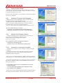
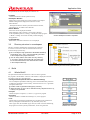
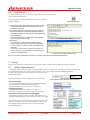
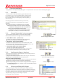
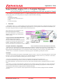
Application Note
SuperH RISC engine C/C++ Compiler Package
APPLICATION NOTE: [Introduction guide]Renesas IDE Start-up guide for SuperH
This document is for SuperH RISC engine C/C++ Compiler Package beginner, explains from product installation, overview of the
contents of the product, next creating the project workspaces, build and execution and debug.
1. Overview
2. Installation Procedures
3. Project Overview, Creating the project
4. Build
5. Execution and Debug
1.
Overview
SuperH RISC engine C/C++ compiler package is the package product which the essential tools to make the high-quality program
that can make use of the performance of SuperH RISC engine family are in. In this product also the simulators are included, so you
can execute, debug and evaluate your program without an actual target board.
Chart 1 shows the overview architecture of the
Renesas Development Environment.
The colored components in “Cooperation Tool
(Software) is the software tools included in the
compiler package.
• High-performance Embedded Workshop
Renesas Development Environment.
This is the common front-end that can operate the
cooperation tools and has many functions such as
an editor , a browser and so on and gives us a
seamless development environment from coding to debug.
• Compiler, Assembler, Linkage Editor
Chart1 Architecture of Renesas Development Environment
The Renesas pure compilers that can generate the high-quality program that can make the best performance of SuperH RISC engine
family. The tool set of the compiler, the assembler and the linker is called as a “toolchain”. By using the “Build” function in the
High-performance Embedded Workshop, you can operate the toolchain and make the software program on the ROM in the MCU.
In other words, we call “Build” as the operations to make the programs on the ROM by operating the toolchain.
• Simulator
This enables the simulation and evaluation of SuperH RISC engine on your PC. You can use various debug functions such as Break
and Trace as well as the simulated MCU functions such as Simulated Interrupt and Timer functions. If you use SH-3 or SH-4 and so
on, a MCU with a cache, the simulation including cache can be also available.
The “Not colored components” is the development tools included in other Renesas Development Tools.
If you buy the Renesas Development tools, you can only install the tools additionally to the current environment.
By installing additionally, the available functions that can be operated by the High-performance Embedded Workshop is added as
Chart1.
For example, if you install E10A-USB emulator additionally after installation of the compiler package, the “E10A-USB Emulator
Control” cooperation software in the Chart1 is added, and you can also execute and debug your program on an actual target with
controlling E10A-USB emulator by High-performance Embedded Workshop.
As described above, you can construct a simple, high-functional development environment by High-performance Embedded
Workshop.
REJ06J0009-0100/Rev.1.00
June 2007
Page 1 of 12
Application Note
2.
Installation
Set the product CD-ROM to your PC and follow the order of an installer.
If High-performance Embedded Workshop has already installed in your PC and the
adding product includes the newer version of High-performance Embedded Workshop,
an installer of the adding product automatically overwrites the current High-performance
Embedded Workshop.
If the adding product includes the Install Manager(Chart2), even if the Highperformance Embedded Workshop has been installed, you can install the Highperformance Embedded Workshop newly into an other directory.
[!] The installation to an other directory when using an Install Manager
is only available when you use Windows 2000 and Windows XP.
To minimize the disk volume, we recommend the overwrite installation.
3.
Chart2 Install Manager
How to create the project workspace
With using SH-2A(SH7206), the creation method is explained.
3.1
Start High-performance Embedded Workshop
Select “High-performance Embedded Workshop” from the start menu of
the windows. Then the “Welcome” dialog box(Chart3) is displayed.
[!] The displayed strings in a start menu may be different according
to what tools you have installed in your PC.
[!] If you have installed more than one High-performance Embedded Workshop
by using an Install Manager(Chart2), only an active High-performance
Embedded Workshop* may be launched.
*Please refer to Online Help of an Install Manager.
3.2
3.2.1
Create a Workspace
Workspace and project(s)
High-performance Embedded Workshop has a concept of “Workspace” and “Project”.
• Workspace
Workspace is a largest unit when you make the program with High-performance
Embedded Workshop. Workspace can have several project(Chart4).
When you create a workspace, more than one project is needed, and one project
is automatically made when you create the workspace.
• Project(s)
When you make the program, sometimes you make a certain function
as a library and make hierarchical levels between several modules.
In such cases, you can also create the library project and insert it to a workspace.
3.2.2
Chart3 “Welcome” dialog box
Chart4 Workspace and project(s)
Create a workspace
If you select “OK” in the “Welcome” dialog(Chart3), “New Project Workspace”
dialog box(Chart5) is displayed.
Select “Application” in the “Project Type” and input “Workspace Name”. If you
want to change “Project Name”, you can change it after inputting workspace name.
[!] If the selected “Directory” exists, you can’t make a new workspace
in a same directory. Please change the “Directory” name.
[!] If you have installed the several kind of the compiler packages,
select “SuperH RISC engine” in the “CPU family”.
[!] If you use SuperH RISC engine C/C++ compiler package V.9 or later,
confirm that “Renesas SuperH Standard” is selected in the “Tool chain”.
REJ06J0009-0100/Rev.1.00
June 2007
Chart5 “New project workspace”
dialog box
Page 2 of 12
Application Note
Select your MCU
Next you select the version of the toolchain and MCU(Chart6).
Select “SH-2A” of “CPU Series”, and “SH7206” of “CPU Types”.
[!] If your MCU is not displayed in “CPU Type”, updating the compiler
package to the newest version may add the MCU.
3.2.3
Select MCU option
“Option Settings” dialog box(Chart7) select the common options among
the compiler, assembler and the linker.
This option can be changed after creating the project.
Press “Next” without changing the default options.
3.2.4
Chart6 Select MCU
Settings of automatically generated files
“Setting the Contents of Files to be Generated” dialog box(Chart8) select the
settings of the files generated automatically by the High-performance Embedded
Workshop.
[!] This document tells you the overview of each settings.
The contents of the automatically generated files, please refer to
the other document, “Explanation of the sample files” application note.
• Use I/O Library
Specify the number of standard I/O streams
[!] When you use the standard I/O streams, you must develop the “LowLevel Interface Routines” according to your system. How to develop
is described on the compiler manual.
• Use Heap Memory
If you use the malloc, realloc or calloc functions or use C++ in your program,
check this.
• Generate main( ) Function
Can be selected from aseembly, C or C++ language.
• I/O Register Definition Files
Generates the I/O registers definition header file usable in C/C++ language.
• Generate Hardware Setup Function
Generates the HardwareSetup function for initialization of MCU.
[!] As an initialization of MCU is depend on your system, you must
add the suitable initialization code in the HardwareSetup function.
Chart7 Select MCU options
Chart8 Settings of auto-generated files
Now select “C/C++ source file” from “Generate Hardware Setup Function”
and press “Next”.
3.2.5
Selection of Standard Libraries
“Setting the Standard Library” dialog box(Chart9) selects the standard library
that you want to use in the project. This selection can be changed after creating
the project. Now press “Next” without changing the selection.
3.2.6
Chart9 Selection of Standard Libraries
Setting of Stack Region
“Setting the Stack Area” dialog box(Chart10) select an initial value of the Stack
Pointer(SP) and the stack size. Originally the stack region is automatically located
near the last(highest) address in the internal RAM of each MCU. These settings
can be changed after creating the project.
Press “Next” without changing the default settings.
[!] If an access to the stack is late, the performance goes worse.
It’s strongly recommended that you place the stack regions
in the internal RAM regions.
REJ06J0009-0100/Rev.1.00
June 2007
Chart10 Settings of Stack
Page 3 of 12
Application Note
3.2.7
Setting of Reset Vectors
“Setting the Vector” dialog box(Chart11) select whether the vector table
files of each MCU makes to be generated. Originally the suitable vector tables
is generated automatically. Press “Next”.
By the procedures described above, all the settings for automatically generated
source files are completed.
3.2.8
Selection of Target(s) when Debugging
“Setting the Target System for Debugging” dialog box(Chart12) selects
the target on which you want to debug the program.
Originally the suitable SuperH simulators according to the selection in
section 3.2.3(Chart6) is displayed automatically. If you have installed
the suitable emulators, they’re also displayed automatically.
In this case, check “SH-2A FPU Cycle Base Simulators” and press “Next”.
Chart11 Settings of Reset Vectors
[!] You can select more than one target.
In this case, you can select one of the several targets from
selecting the “Debug Sessions”(Section 5.1) when debugging.
3.2.9
Settings of the Debugger Options
Chart12 Selection of Target
“Setting the Debugger Options” dialog box(Chart13) select the initial
option settings to each debug target selected on Chart12.
You don’t have to set any settings on this dialog box.
Press “Next” to continue.
[!] If you select more than one targets, this dialog box
is displayed for each debug target.
You don’t have to do any settings to these dialog boxes.
3.2.10
Generation of a workspace completed
Chart13 Setting of Debugger Options
Through the above settings, a necessary settings for creating a workspace
is completed.
“Changing the File Names to be Created” dialog box(Chart14) displays
the list of files and overviews that is generated by High-performance
Embedded Workshop automatically.
Pressing “Finish” on Chart14 displays the “Summary” dialog box(Chart15).
In this dialog you can confirm the detailed information of a created workspace.
If you check “Generate Readme.txt as a summary file in the project directory”,
the contents of “Summary” dialog is saved to ReadMe.txt file in the project
directory(See section 3.3).
Chart14 List of auto-generated files
[!] The detailed information saved in the ReadMe.txt is that when
creating the project.
If you change the settings/selection after creating the project,
it isn’t reflected to the ReadMe.txt.
Pressing “OK” in Chart15 starts the High-performance Embedded Workshop
with opening the created workspace, shows the status displayed in Chart16.
Chart15 Details of generated project
REJ06J0009-0100/Rev.1.00
June 2007
Page 4 of 12
Application Note
An explanations for the terms displayed in Chart16 are:
• Toolbars
Contains the buttons to do the operations easily.
• Workspace Window
Displays the project and the project files included in a workspace.
Double-clicking the file displays the contents of it in the
Editor Window.
Workspace Windows is made by four tabs. Browser function,
Test function etc. are usable in the other tabs.
• Editor Window
Source files can be displayed and edited.
When debugging, editor window is also used as a debugger.
So the sequential operations, “Debug”->”Modify the source program”
->”Build”->”Debug” can be done smoothly without changing
the application.
• Output Window
Build results, execution results and so on are displayed.
3.3
Chart16 Workspace creation completed
Directory structure in a workspace
Directory structures automatically generated by the operations
in section 3.2 is shown in Chart17. Generated source files are
located in the project directory.
[!] Do not modify the High-performance Embedded Workshop
system files(*.hws, *.hwp, *.hsf) automatically generated
in the workspace and project directories.
[!] You can freely add the source files from any directory.
If you want to add the source files with new directories,
it’s recommended that the new directories are located
in the workspace directory.
Chart17 Directory structure of auto-generated files
4.
4.1
Build
What’s Build?
The operation that make the toolchain to control in order to generate
the program is called “Build”. The flow of the “Build” is displayed in Chart18.
The terms in Chart18 is described below.
• Library Generation(Construction of a Standard Library)
You can adapt the optimization technology even to the standard library functions.
To adapt the optimization, at first a library, selected in section 3.2.6, is generated
(compiled) when build.
[!] It takes a while to generate a library(Only one time).
[!] When the option in “CPU” tab or “Standard Library” tab(See section 4.2),
a library is re-generated.
• Compile
Launch compiler to compile C(*.c) and C++(*.cpp) source program.
• Assemble
Launch assembler to assemble the assembly(*.src) source program.
• Link
Launch linker to generate the load module file(*.abs) that can be executed on a
MCU by linking the intermediate files(*.obj) and library files(*.lib).
The S-Type(*.mot) file and HEX-Type(*.hex) file, which is used for transferring
the program to an actual system by ROM writer, can be also generated.
REJ06J0009-0100/Rev.1.00
June 2007
Chart18 Flow of “Build”
Page 5 of 12
Application Note
4.2
4.2.1
Build Options
Setting of the “Build Options”
Select “SuperH RISC engine Standard Toolchain…” from “Build” menu.
“SuperH RISC engine Standard Toolchain” dialog box(Chart18) is displayed.
All the options of the tools in a toolchain can be selected by this dialog box.
• “C/C++” tab
Compiler options can be selected in this tab.
• “Assembly” tab
Assembler options can be selected in this tab.
• “Link/Library” tab
Linker options can be selected in this tab.
[Information]
SuperH Linker have an optimization function.
So sometimes called as an “Optimized Linkage Editor”.
• “Standard Library” tab
Options when generating the standard library can be selected in this tab.
• “CPU” tab
Common MCU options(3.2.4) can be selected in this tab.
• “Debugger” tab
Memory setting of a debug target(3.2.9) can be set in this tab.
This also can be set in the “Memory Map Window”, so you don’t
have to use this tab.
4.2.2
Chart18 Option dialog box for Build
Scope of build options
Originally the build options are commonly set for all project files in
the project. You can also select various options to each file.
To set the options individually, select the file according to Chart19.
You can select both a file(Left) and multiple files(Right) by using
“Ctrl” or “Shift” keys.
(Select one file)
(Select multi files)
Chart19 Selection of files for build options
In this case, you don’t have to change any options from the default settings.
4.3
What’s “Configuration”?
It’s convenient that option settings in 4.2 are saved and can be changed to evaluate various option settings.
High-performance Embedded Workshop has a unit concept of “Configuration” to ensure such operations.
By registering/changing the “Configuration”, you can save/change the various option settings and evaluate each option settings.
Originally “Debug” and “Release” configurations exist. The intermediate
files of each configuration generated during build is saved to each
configuration directories dependently shown in Chart17.
Chart20 “Build” toolbar
You can easily evaluate various option settings without overwriting
intermediate files by creating configurations for each option setting.
(Left-side drop-down list is the “Configuration”)
To change configuration, you have only to select the configuration
dropdown list from the “Build” toolbar(Chapter20).
[!] Originally the difference between “Debug” and “Release” configurations is only whether to generate a debug
information or not. These two configurations generate a same program.
You don’t have to use “Release” configuration.
In this case, select “Debug” configuration.
REJ06J0009-0100/Rev.1.00
June 2007
Page 6 of 12
Application Note
4.4
How to Build
In order to build the project, press “F7” key or select “Build” from “Build” start menu,
or press “Build” button(Chart21).
If no error happens in the Output Window(Chart16), you’ve made the
program completely.
[!] To build the project, option dialog box(Chart18) must be
closed. When this dialog box is closed, the options of a
toolchain is confirmed.
[!] If you build the project without changing any contents of
the files automatically generated by High-performance
Embedded Workshop, L1100 warning message(Chart23)
may be displayed.
This means that there’s no ROM data in the project file.
So you can ignore this warning.
[Information]
If you get errors or warnings during build, pressing
“F8” key displays the error line of the file automatically
in case of an error or warning is that of a compiler or an
assembler.
If you point a mouse cursor on the line of an error or a
warning, pressing “F1” key displays a context help of an
error or a warning(Chart23).
Chart21 Build button
Chart22 “L1100” warning
Chart23 Context help for Build Error(s)
Now you’ve made the executable program on a target by High-performance Embedded Workshop.
5.
Debug
In this section, operations to transfer the program generated in section 4 and procedures to debug the program is explained.
5.1
What’s “Debug Session”?
As the option setting for the files can be saved and managed as a unit of “Configuration”, the debug environment settings also can
be saved and managed as a unit concept of “Debug Session” in the project of High-performance Embedded Workshop.
To change the debug session, select “Debug Session” drop-down list in
“Build” toolbar(Chart).
An information which is saved to a debug session is the following:
Chart24 Build toolbar
(Right-side drop-down list is the “Debug Session”)
• Connected Target
A target on which the generated program is executed and debugged.
You can select both simulators and installed emulators.
Originally the selected target in section 3.2.9 is registered.
• Debugging Program
Load Module file(Executable program: *abs, *.mot, etc.).
Originally the *.abs file of a selected configuration is registered.
• Information of the window(s) when debugging
Window(Register Window, Memory Window, Watch Window, etc.)
information when debugging can be saved directory with a using image.
So if you save a debug session(Usually this is automatically done when
closing the workspace), when you re-start the debug, you have only to
select a debug session saved before to recover the previous debug
environment(Figure25).
Chart25 Recover of “Debug Environment”
REJ06J0009-0100/Rev.1.00
June 2007
Page 7 of 12
Application Note
5.2
Connecting to the Target
To connect to the target, select the target registered in a drop-down list of debug sessions(Chart24).
In this case, select “SimSessionSH2A-FPU_Cycle” debug session. This debug session is made by a selection in section 3.2.9
when you create a workspace. Selecting the debug session makes the High-performance Embedded Workshop to launch the
cooperation software(Chart1) to connect the target.
If you select the simulator as a connecting target, “I/O DLL” dialog
box(Chart26) is displayed. This dialog box is for setting peripheral
modules functions of a selected simulator. If you check the modules
displayed in “Module Name”(In Chart26 CMT: Compare Match
Timer), the checked module is valid in a selected simulator.
In this case, press “OK” without checking any modules.
After launching the simulator, the toolbars for debugging are added
in upper part of High-performance Embedded Workshop(Chart27)
in order to execute and debug the program.
Chart26 “I/O DLL Settings” dialog box
[!] In case of using emulator, the specific settings may be needed when connecting the target.
For details, please refer to the emulator user’s manual and an application note for the emulator.
Chart27 Toolbar displays before/after launching the simulator(Upper:Before Lower:After)
If the connection to the target succeeded, “Connected” is displayed in Output Window(Chart16).
5.3
Download a debugging program to target
Next you should download the debug program to the target.
When you connect to the target, “Download modules” folder and the
load module program(*.abs) were added in the “Project” tab in the
“Workspace Window”(Chart16).
Double-clicking the load module program downloads the program file
to the target. After downloading, raw-mark is displayed on a load module
program file(Chart28 Lower).
[!] The number in the right-side of a load module file is “Offset Address”.
You must set “00000000” as an offset address.
(Default setting is the “00000000”).
[!] If you use an emulator and the load module program needs
loading to external memory(not in MCU), you must set the
port and the bus controller registers before downloading.
REJ06J0009-0100/Rev.1.00
June 2007
Chart28 Download a program
(Upper:Before download,
Lower:After Download)
Page 8 of 12
Application Note
5.4
Execution and Debug
A preparation for executing and debug the program was completed. In this section, let’s execute and debug the program.
5.4.1
Reset MCU
At first, reset MCU and confirm that the program start from the first.
To reset MCU, press “CPU reset” button(Chart29). So MCU gets the
Power-On reset address and a initial data for the stack pointer from
the vector table, and stops on the beginning of PowerON_Reset_PC
function(Chart30).
Thus, High-performance Embedded Workshop automatically
shows the source program if a stopped address has a suitable
source file.
[!] If a source program is not displayed even if a stopped
address has a suitable source file, check the followings:
・Whether the debug option for both the compiler and
linker. You must select this option for both.
・Whether the source file is not moved after building
the program. If moved, you must rebuild the project.
5.4.2
Chart29 “CPU Reset” button
Chart30 Status after MCU Reset
Change “Display Mode” of source program
You can change “Display Mode” by pressing the “Display Mode”
button(Chart31) located on a Left-Upper side of an Editor Window.
Chart31 “Display Mode” button
• “Source Mode” button (Chart31:Left)
This mode is for displaying and editing the source file(Chart30).
[!] To edit a source file, you must change this mode.
• “Mixed Mode” button (Chart31:Middle)
This mode can be displayed both source codes and disassembly codes.
As disassembly codes are displayed under the correspondent source code,
it’s convenient to analyze the details of the object codes.
• “Disassembly Mode” button (Chart31:Right)
This mode only displays the disassembly code.
Even if you don’t have a correspondent source code, such as a library,
you can confirm the detailed object codes by this display mode.
5.4.3
Step Execution (Step-In, Step-Over)
Pressing the “Step Execution” button makes MCU to execute step instruction.
• Step-In button (Chart33 Left)
“Step-In” execution. If you press this button on the call point of the function,
program stops on the beginning point in the called function.
• Step-Over button (Chart33 Right)
“Step-Over” execution. If you press this button on the call point of the function,
program stops on the next line after executing the called function.
[!] When step executing, if a source file of a stop point doesn’t exist(such
as call of a library function etc.), display mode is automatically changed
to “Disassembly Mode”.
5.4.4
Chart32 “Mixed Mode” display
Chart33 “Step Execution” buttons
(Left: Step-In, Right: Step-Over)
Chart34 “Registers” button
Referring and Editing MCU Register
Pressing the “Registers” button shows the “Register Window”(Chart35).
You can confirm the register value by this window. For example, if steps with
opening this window, you can confirm that the PC(Program Counter) is updated.
You can also change the value of the registers. By double-clicking a register,
“Register Setting” dialog box(Chart35 Right) is displayed.
You can input a value to the register.
REJ06J0009-0100/Rev.1.00
June 2007
Chart35 Refer/Edit register(s)
Page 9 of 12
Application Note
5.4.5
Referring the Definition of Function/Variables
In the workspace window(Chart16), select “Navigation” tab.
A list of functions and global variables in the program are displayed.
Double-click the “main(void)” in the “C Functions”(Chart36) to display
the definition of the “main” function in an editor window.
5.4.6
Setting the Breakpoint(s)
Next let’s set a breakpoint to a program.
If you do the operation described in section 5.4.5, a mouse cursor is
located on the beginning of the main function. Press “F9” key or
double-click the “S/W(Software) Breakpoints” column in the left-side
of the Editor Window.
The “●” mark is displayed on the “S/W Breakpoints” column.
5.4.7
Execute the program
Chart37 Setting the breakpoint(s)
To execute the program, press “F5” key or “Execution” button(Chart38).
The program starts from the stopping point and stops at the point
on which the software breakpoint is set(Chart39).
[!] If more than one source lines has a same program address
(Chart39), a breakpoint and the stopped point(array display)
may be separately displayed.
5.4.8
Chart38 “Execution” button
Watch of the variable(s)
To refer or modify the valuables, press “Watch” button(Chart40).
“Watch Window”(Chart41) is displayed. Register the valuables which you
want to refer or modify in this window.
You can also register a valuable to Watch Window directly by doubleclicking a valuable(reverse-colored), drugging it and drop it on the
Watch Window.
[!] There is no valuable in the project automatically generated
by High-performance Embedded Workshop according to
the operations explained in section 3.
5.4.9
Chart36 “Navigation” tab
Chart39 Stop on a breakpoint
Chart40 “Watch” button
Change(Edit) the program and evaluation
If you want to modify the source program while debugging, you can
easily build and evaluate the revised program again
by the following procedures.
Chart41 “Watch” window
•
• Change the display mode to “Source Mode”(See 5.4.2) and modify the source program.
• Press “F7” key or “Build” button(See 4.4). Modified source files are built automatically.
• From the procedures described 5.3, download the program to a target.
•
(If download is automatically done after build, you don’t have to do this operation)
6.
What to do next?
This application note explained from installation to simple debug method for Renesas Development Environment beginners.
If you want to evaluate the program continuously by using a simulator, it’s recommended to refer to an another application note
“SuperH RISC engine Start-Up Guide (2) Simulator Debug”. In this application note, you can learn standard debug functions by
using a demonstration project.
If you want to use emulators, you can use the tutorial program included in the emulator product. For details, please refer to the
User’s manual and the application note of the emulator.
REJ06J0009-0100/Rev.1.00
June 2007
Page 10 of 12
Application Note
Website and Support <website and support,ws>
Renesas Technology Website
http://japan.renesas.com/
Inquiries
http://japan.renesas.com/inquiry
[email protected]
Revision Record <revision history,rh>
Rev.
1.00
Date
Jun.01.07
REJ06J0009-0100/Rev.1.00
Description
Page
Summary
—
First edition issued
June 2007
Page 11 of 12
Application Note
Notes regarding these materials
1.
2.
3.
4.
5.
6.
7.
8.
9.
10.
11.
12.
13.
This document is provided for reference purposes only so that Renesas customers may select the appropriate
Renesas products for their use. Renesas neither makes warranties or representations with respect to the
accuracy or completeness of the information contained in this document nor grants any license to any intellectual
property rights or any other rights of Renesas or any third party with respect to the information in this document.
Renesas shall have no liability for damages or infringement of any intellectual property or other rights arising out
of the use of any information in this document, including, but not limited to, product data, diagrams, charts,
programs, algorithms, and application circuit examples.
You should not use the products or the technology described in this document for the purpose of military
applications such as the development of weapons of mass destruction or for the purpose of any other military
use. When exporting the products or technology described herein, you should follow the applicable export
control laws and regulations, and procedures required by such laws and regulations.
All information included in this document such as product data, diagrams, charts, programs, algorithms, and
application circuit examples, is current as of the date this document is issued. Such information, however, is
subject to change without any prior notice. Before purchasing or using any Renesas products listed in this
document, please confirm the latest product information with a Renesas sales office. Also, please pay regular
and careful attention to additional and different information to be disclosed by Renesas such as that disclosed
through our website. (http://www.renesas.com)
Renesas has used reasonable care in compiling the information included in this document, but Renesas
assumes no liability whatsoever for any damages incurred as a result of errors or omissions in the information
included in this document.
When using or otherwise relying on the information in this document, you should evaluate the information in light
of the total system before deciding about the applicability of such information to the intended application.
Renesas makes no representations, warranties or guaranties regarding the suitability of its products for any
particular application and specifically disclaims any liability arising out of the application and use of the
information in this document or Renesas products.
With the exception of products specified by Renesas as suitable for automobile applications, Renesas products
are not designed, manufactured or tested for applications or otherwise in systems the failure or malfunction of
which may cause a direct threat to human life or create a risk of human injury or which require especially high
quality and reliability such as safety systems, or equipment or systems for transportation and traffic, healthcare,
combustion control, aerospace and aeronautics, nuclear power, or undersea communication transmission. If you
are considering the use of our products for such purposes, please contact a Renesas sales office beforehand.
Renesas shall have no liability for damages arising out of the uses set forth above.
Notwithstanding the preceding paragraph, you should not use Renesas products for the purposes listed below:
(1) artificial life support devices or systems
(2) surgical implantations
(3) healthcare intervention (e.g., excision, administration of medication, etc.)
(4) any other purposes that pose a direct threat to human life
Renesas shall have no liability for damages arising out of the uses set forth in the above and purchasers who
elect to use Renesas products in any of the foregoing applications shall indemnify and hold harmless Renesas
Technology Corp., its affiliated companies and their officers, directors, and employees against any and all
damages arising out of such applications.
You should use the products described herein within the range specified by Renesas, especially with respect to
the maximum rating, operating supply voltage range, movement power voltage range, heat radiation
characteristics, installation and other product characteristics. Renesas shall have no liability for malfunctions or
damages arising out of the use of Renesas products beyond such specified ranges.
Although Renesas endeavors to improve the quality and reliability of its products, IC products have specific
characteristics such as the occurrence of failure at a certain rate and malfunctions under certain use conditions.
Please be sure to implement safety measures to guard against the possibility of physical injury, and injury or
damage caused by fire in the event of the failure of a Renesas product, such as safety design for hardware and
software including but not limited to redundancy, fire control and malfunction prevention, appropriate treatment
for aging degradation or any other applicable measures. Among others, since the evaluation of microcomputer
software alone is very difficult, please evaluate the safety of the final products or system manufactured by you.
In case Renesas products listed in this document are detached from the products to which the Renesas products
are attached or affixed, the risk of accident such as swallowing by infants and small children is very high. You
should implement safety measures so that Renesas products may not be easily detached from your products.
Renesas shall have no liability for damages arising out of such detachment.
This document may not be reproduced or duplicated, in any form, in whole or in part, without prior written
approval from Renesas.
Please contact a Renesas sales office if you have any questions regarding the information contained in this
document, Renesas semiconductor products, or if you have any other inquiries.
© 2007. Renesas Technology Corp., All rights reserved.
REJ06J0009-0100/Rev.1.00
June 2007
Page 12 of 12