1
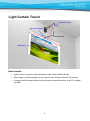
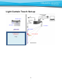
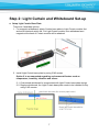
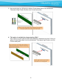
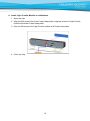
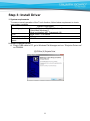
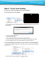
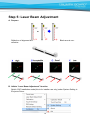
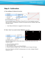
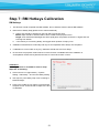
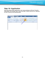
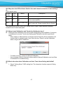
User Manual v 1.0 March 2014 ENGLISH TOUCH SYSTEM for Interactive Projectors TRIUMPH BOARD PJ2000i UST DLP TRIUMPH BOARD PJ3000i UST-W DLP TRIUMPH BOARD a.s., Neklanova 122/15, 128 00 Prague 2, Czech Republic, www.triumphboard.com 1 Table of Contents Usage Notice ....................................................................................................................... 3 Light Curtain Touch .............................................................................................................. 4 Light Curtain Touch Set-up .................................................................................................. 5 Step 1: Projector Set-up....................................................................................................... 6 Step 2: Light Curtain and Whiteboard Set-up ...................................................................... 7 Step 3: Install Driver........................................................................................................... 11 Step 4: Touch Area Setting ................................................................................................ 12 Step 5: Laser Beam Adjustment ........................................................................................ 15 Step 6: Calibration ............................................................................................................. 20 Step 7: RM Hotkeys Calibration ......................................................................................... 21 Step 8: Mode Selection ...................................................................................................... 22 Step 9: Touch Sensitivity .................................................................................................... 23 Step 10: Application ........................................................................................................... 24 Trouble-shooting ................................................................................................................ 25 2 Usage Notice Please follow all warnings, precautions and maintenance as recommended in this user's manual. Warning - Do not disassemble Light Curtain module/IR camera. Warning - Do not use, store, or leave Light Curtain module/IR camera near fire, or in places with a high temperature, e.g., in direct sunlight, or in sun-heated cars. Warning - Use standard USB cable (maximum length: 5m). To extend USB cable length over 5m, a certified active extension USB cable is required. Warning - Do not allow liquid or foreign material enter Light Curtain module/IR camera Precautions IR camera on projector receives infrared signal from Light Curtain module which is attached to the wall. To operate normally: IR camera should face the projection image area on the wall. Remove any obstacle in between IR camera and Light Curtain module. Do not place other infrared communication devices, lighting equipment, or residential heating equipment etc., nearby. Maintenance: Gently clean the optical port with dust blower. 3 Light Curtain Touch IR Camera module Light Curtain module Interactive cable Whiteboard How it works Light Curtain covers the entire whiteboard with a thin invisible IR light. When finger or stylus breaks into the Light Curtain, IR light reflects to IR camera. Camera module tracks multiple touch points and reports positions to a PC or laptop via USB. 4 Light Curtain Touch Set-up AC Power Projector Lens Display by VGA or HDMI USB Interactive cable IR Camera IR Camera Light Curtain Light Curtain IR Light Curtain Illumination Scattering light Image Whiteboard 5 Step 1: Projector Set-up A. Plug in IR Camera Module Step 1 Step 2 Plug in IR camera module Remove the corner cover B. Install Wall Mount and Projector 6 Step 2: Light Curtain and Whiteboard Set-up A. Setup Light Curtain Base Plate There are 4 available options: 1. For magnetic whiteboard: attach Curtain base plate to Light Curtain module first and avoid interlock switch fail. Put Light Curtain module onto whiteboard and magnets at the back of Curtain module will be attached. 2. Install Light Curtain base plate by using 2 M3 screws Option 2 is recommended regarding environmental factors such as temperature, humidity, vibration and others. 2-1. Customized whiteboard is incorporated with Light Curtain base plate design. 2-2. Regular whiteboard, the Light Curtain base plate needs to be installed first by using 2 M3 screws. 7 3. Use special glue (ex: AB glue) to adhere Curtain base plate to the whiteboard. Then place Light Curtain module onto Curtain base plate. 4. This option is suitable for demonstration ONLY. Use a piece of good quality double-sided adhesive (thickness less than 0.5mm) to adhere Curtain base plate onto the whiteboard. Then place Light Curtain onto the Curtain base plate. 8 B. Whiteboard frame suggestion If whiteboard frame thickness is over 3mm, reflected light interference from whiteboard frame may be detected by IR camera and influence Touch function. It is suggested to keep at least 50mm at left/right and 100mm at bottom. If whiteboard frame thickness is less than 3mm, ensure reflected light interference is not observed while doing Step 5 Laser Beam Adjustment. Therefore, it is suggested to use whiteboard frame less than 3mm, or follow below whiteboard frame condition: - Surface treatment: Matt, with mold texture ≥11010 - Shape: as figure below C. How to Setup whiteboard 9 D. Install Light Curtain Module on whiteboard. 1. Open top cap. 2. Align the M4 screw hole to the Curtain base plate; magnets at back of Light Curtain module will attract Curtain base plate. 3. Use one M4 screw to fix Light Curtain module and Curtain base plate 4. Close top cap. 10 Step 3: Install Driver 1. System requirements To ensure normal operation of the Touch function, follow below requirement to check your system condition. System requirement Operating system Microsoft Windows XP (SP3)/Windows 7 (32bit/64bit)/Windows 8 (Must be installed. NET Framework 4.0) CPU Intel® Core™ i3 or above Memory 2GB or more Minimum hard disk 110 MB space 2. Install iProjector Driver A. Plug in USB cable to PC, go to Windows File Manager and run “iProjector Driver.exe” on CDROM. 11 Step 4: Touch Area Setting There are two Touch Area Setting modes: Auto and Manual. A. Execute Auto Touch Area Setting: If fail message pops up, follow below steps to trouble-shoot and re-run Auto Touch Area Setting: a. Quit all software application b. Reduce ambient light c. Do not obstruct or shake lens during Touch Area Setting d. Check if projection image is clear. If not, adjust focus to sharpen the image If the fail message still pops up, switch to Manual Touch Area Setting. B. Touch Area Setting is for installer use only. If Auto Touch Area Setting fails: Switch “ON” Installation mode(this is for installer use only) under System Setting in iProjector Driver. Select “Manual” to execute Manual Touch Area setting. 12 B-1. Wait for Touch Area Setting test pattern. B-2. After the camera captures the projection image, a Touch Area window will pop up. If the captured image is not clear enough, please re-select “Ambient light mode selection” from “Auto” to “Bright” or “Dim” according to actual ambient light condition. Then press “Preview” and the camera will re-capture the image. B-3. Touch Area Boundary Fine-tuning 13 Step 1: Click on P1 then move the mouse cursor within the window. Step 2: Left click the mouse to adjust the green frame at the P1 corner. The green frame should locate between the effective projection area and reflected light spots of whiteboard frame. Release the button when adjustment is done. Step 3: Use the same method to adjust green frame at P2, P3 and P4. Step 4: Finally, check again if all the green frame locate correctly in the designated area. If not, adjust again. B-4. Exit Touch Area Setting When the Touch Area is delineated, click to “Exit.” Note: If Touch function is not responding at the edge of projection area, slightly relocate the green frame outside of Touch Area test pattern. 14 Step 5: Laser Beam Adjustment A. Purpose Reflection of alignment bar: White area reflects Laser beam. Black area is nonreflective. B. Initiate “Laser Beam Adjustment” function Switch “ON” Installation mode(this is for installer use only) under System Setting in iProjector Driver. 15 The function of “Laser Beam Adjustment” displays a real time image from IR camera. C. Attach the Alignment Bars: This is a full-screen image with alignment bar positions indicated to be attached. D. How to Adjust Laser Beam: D-1 Open the Top Cap: Open the top cap of Light Curtain module. There are 6 screws with 6 corresponding positions of alignment bars. 16 D-2 Plug in Interactive cable. Interactive Cable (DC power) D-3 How to adjust when Laser beam is too high or low 17 D-4 Right-hand side adjustment order: 1. Attach alignment bars 2. Adjust screws in the order of R1→R3→R2. a. Adjust R1 screw until 3 light spots appear at bar R1. b. Adjust R3 screw until 3 light spots appear at bar R3. c. Finally, adjust R2 screw until 3 light spots appear at bar R2. d. Fine-adjust if necessary. e. Remove alignment bars. When the screw ties or sounds 'cluck', stop and see Question 7 for troubleshooting 18 D-5 Left-hand side adjustment order: 1. Attach alignment bars 2. Adjust screws in the order of L1→L3→L2. a. Adjust L1 screw until 3 light spots appear at bar L1. b. Adjust L3 screw until 3 light spots appear at bar L3. c. Finally, adjust L2 screw until 3 light spots appear at bar L2. d. Fine-adjust if necessary. e. Remove alignment bars. D-6 Close Light Curtain top cap D-7 Quit Laser Beam Adjustment Mode Click to “Exit” 19 Step 6: Calibration A. Execute Manual Calibration Procedure Touch the target marks on the screen. (Press “Esc” key to exit calibration anytime.) After the 4th point of Calibration is finished, the system will save Calibration data. Wait until data is saved. Note: Manual Calibration is suggested for better accuracy. B. Select “Auto” to execute the Auto Calibration procedure. If the fail message pops up, follow below steps to trouble-shoot and perform Auto Calibration again. a. b. c. d. Close all software application Reduce ambient light Do not obstruct or shake lens during calibration Check if projection image is clear. If not, adjust focus to sharpen the image If the "Auto Calibration still failed" message pops up on screen, change to Manual Calibration mode. 20 Step 7: RM Hotkeys Calibration RM Hotkeys 1. This function should cooperate with RM software. Do not start this function without RM software. 2. Placement of Hotkey Strip (please refer to mail as attached) a. Hotkey strip should be attached on the both side of projection area Width: Strips should be attached within 10mm outside of the projection area Height: If we divided the WB height into three equal parts, the position should be no higher than 2/3 counting from bottom. b. If the first key is not working ideally, we suggest lower position of strip by 5cm. 3. Calibration should be done continually and only be accomplished when 20keys are completed. 4. If calibration is not accurate on any key, calibration should start over from Step1. 5. Do not touch the projection area because no touch function is available before the calibration is accomplished. Please use keyboard and mouse to control when there is need. Calibration: 20 hotkey features is available for user to setup. Steps are as following: 1) Click on driver icon (right bottom) – System Setting – RM Hotkey – and choose Hotkey Setting 2) Use stylus to point Hotkey strip icons according to black/red target. 3) Press in the middle of icon (about 1s) till the target will point to next. Continue with 20 steps to the end of calibration 21 Step 8: Mode Selection Select Mode as Touch Mode or Mouse Mode. For Windows 7/8: Windows 7 and Windows 8 operating system support multi-point touch control. Users can select default Touch Mode for multi-point touch or switch to Mouse Mode. Only Mouse Mode is available for Windows XP. 22 Step 9: Touch Sensitivity When touch function is insensitive or writing is intermittent, sensitivity could be enhanced by adjusting Touch Sensitivity level. 23 Step 10: Application After executing software application, users can experience multi-touch function immediately. For example, launch Paint from Win7 or Win 8 and click on “Brushes” to draw 10-touch point simultaneously. 24 Trouble-shooting Q1. Why cannot the PC boot when the USB cable which connects PC and projector is already plugged in? A: 1. Unplug USB cable from PC; or 2. Go to BIOS setup page of PC and modify the “Boot priority order.” Choose Hard disk as top priority, save the change and restart PC. Q2. What to do when Windows system cannot identify the USB device? A: 1. Unplug/re-plug in the USB cable and check again. 2. Switch to another USB port and check again. 3. Restart your computer and check again. 4. Go to Power Options in Control Panel, check USB selective suspend settings status in USB settings under Advance Settings. Switch to “Disabled”. 5. Go to official website of the laptop/PC manufacturer, and update USB driver to latest version. 6. Use the USB cable included with your projector and check again. If an USB extension is needed, please contact your distributor. 7. The USB port of your computer maybe not working. Please contact your IT staff. Q3. Why iProjector Driver icon( A: )is not connected( )? Unconnected icon( ) indicates fail connection, this may be caused by following: 1. Check if interactive function is enabled via OSD selection 25 2. 3. 4. 5. Unplug/re-plug in the USB cable and check again. Switch to another USB port and check again. Restart your computer and check again. Go to Power Options in Control Panel; check USB selective suspend settings status in USB settings under Advance Settings. Switch to “Disabled”. 6. Go to official website of the laptop/PC manufacturer, and update USB driver to latest version. 7. Use the USB cable included with your projector and check again. If an USB extension is needed, please contact your distributor. 8. The USB port of your computer maybe not working. Please contact your IT staff. 26 Q4. Why does the LED indicator flash in blue and interactive function is not working? A: LED indicator table LED LED Status Description Blue Red On Off Normal System is working normally. Flash Off Interlock switch Fail Please check if Light Curtain module is installed at the correct position. OFF On Light Curtain Fail If LED indicator remains in red, this indicates Light Curtain fail. Please contact Service Center. This represents interlock switch fail. Please check if Light Curtain Module is properly located on the Curtain base plate. Q5. When should Calibration and Touch Area Setting be done? A: Please perform Calibration and Touch Area setting during first installation. If projector or whiteboard is moved, Touch Area Setting and Calibration should be performed again. - When Laptop or NB resolution is changed, below iProjector Driver notification will remind users to calibrate again. User could choose “Cancel” and do Calibration when a larger offset is observed. - For better accuracy, please do Manual Calibration. If an overlarge offset is observed, please perform Manual Calibration and see Step 6 Calibration for troubleshooting. Q6. What to do when Auto Calibration and Auto Touch Area Setting both failed? A: 1. Check “Ceiling Mount” OSD setting first. The interactive function supports Ceiling Mode only. 27 2. When projector OSD message is shown, this may result failure to Auto Calibration and Auto Touch Area Setting. Please wait until OSD message is gone before performing Auto Calibration and Auto Touch Area Setting. 3. Please follow below trouble-shooting steps to perform Auto Calibration and Auto Touch Area Setting again. a. Quit all software application b. Reduce ambient light c. Do not obstruct or shake lens during Calibration d. Check if projection image is clear. If not, adjust focus to sharpen the image. e. If the “Auto Touch Area Setting failed” or "Auto Calibration failed" message pops up on screen again, please switch to Manual Mode to do Touch Area Setting and Calibration. 4. Please check Projector Lamp Power Mode selection. Lower lamp brightness (ECO mode) may affect both Auto Touch Area Setting and Auto Calibration. Please switch to Normal mode to complete Touch Area Setting and Calibration. 5. Please check Projector Color Mode selection. To ensure accuracy of both Auto Touch Area Setting and Auto Calibration, it is suggested to switch Color mode to Bright Mode. 28 Q7. What to do when the screw ties or sounds 'cluck'? A-1: If screw R1/L1 ties and cannot tighten further, stop adjusting screw R1/L1, and: 1a) Adjust R2/L2 by same screwing direction encountered from R1/L1, until bar R1/L1 is clear. (For example, if R1 ties while screwing clock-wisely , then adjust R2 clock-wisely accordingly.) 2a) Re-do right/left adjustment order as 1 → 3 → 2 3a) Fine adjust if needed A-2: If screw R3/L3 ties and cannot tighten further, stop adjusting screw R3/L3, and: 1a) Adjust R2/L2 by same screwing direction encountered from R3/L3, until bar R3/L3 is clear. (For example, if R3 ties while screwing clock-wisely, then adjust R2 clock-wisely accordingly.) 2a) Re-do right/left adjustment order as 1 → 3 → 2 3a) Fine adjust if needed Q8. What to do when the mouse cursor ( ) flashes or jumps on screen, or when Touch function does not work well at certain projection area? A: 1. Check if there is strong light shown on the whiteboard. If yes, turn off the light. 2. Check if there is any foreign object on the whiteboard. If yes, remove the object. 3. Switch “On” to initiate Installation mode under System Setting in iProjector Driver and perform Laser Beam Adjustment to check if Laser beam is hitting the whiteboard. Please refer to Step 5 Laser Beam Adjustment for detailed procedures. 4. Switch “On” to initiate Installation mode under System Setting in iProjector Driver and perform Step 4 Manual Touch Area setting to check if Touch Area boundary is delineated properly. Q9. What to do when projection area corner is insensitive or intermittent lines are observed? A: 1. Adjust the level of Touch Sensitivity to enhance sensitivity, see Step 8 Touch Sensitivity for trouble-shooting. 2. If Touch function remains insensitive, please check the optical port condition. If dust or particles are observed, gently clean the optical port with dust blower. 29 Q10. What to do when Touch function is not accurate? A: Touch accuracy may be impacted when Windows default display setting under Windows has been changed. 1. Go to the setting page <Start menu/Control Panel/Appearance and Personalization> 2. Select “Smaller - 100%(Default) ” and click “Apply”. Q11. Why visual keyboard is not working under Mouse Mode of Windows 7 Operating System? A: iProjector Driver function may be restricted by <User Account Control, UAC> setting of the Windows 7 Operating System. Please see following steps to modify: 1. Go to the setting page <Start menu/Control Panel/UserAccounts>. 30 2. Select <Change User Account Control settings> 3. Change the level of User Account Control to "Never notify" and then click "OK" to confirm. 4. Restart the computer to complete the process 31 Appendix A: Specification I. IR Camera Module ID Size(W*L*H) Weight Power Consumption 104.7 (W) x 118.3 (L) x 71.5(H) mm ≤165g 5V/0.3A II. Light Curtain Module Laser Safety Curtain to Screen Distance LED Indicator I/O Port ID Size(W*L*H) Weight Power Consumption Class 1 20mm~70mm @100” Blue/Red Interactive Jack x1 330.2 (W) x 50.7 (L) x 41.1 (H) mm ≤330g 12V/0.2A III. General Specifications Calibration Multi-touch Multi-touch Min. Distance Working Projection Image Size Display mode IR camera installation 4 points Manual Calibration for Windows Auto calibration supported 10-touch points (Win 7 and Win8 compliant) ≥40mm 75”~100” @WXGA co-operate with TR0.35 projector Support Ceiling mode only IR camera cannot support hot plug. Before installation, please ensure AC power cord is unplugged from projector IV. Software Driver OS Required: System Requirements Processor Type RAM Min. HHD Space Microsoft Windows XP (SP3): Mouse mode supported. Windows 7/Windows 8: Touch mode-10 touch points supported and Mouse mode supported (Windows: .NET Framework 4.0 installation is required) TM Intel Core i3 or above 2GB or More 110 MB 32 Appendix B: Accessory Item Description Quantity Light Curtain Module 1 1 IR Camera 2 1 Screw M3 3 2 Screw M4 4 1 Interactive cable 5 1 Alignment Bars 6 3 Curtain base plate 7 1 33 5m USB A to mini USB B cable 8 1 Passive Pen 9 2 CD 10 11 3 Quick Start Card 1 34