1
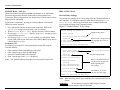
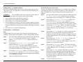
MILLENNIUM
2-Channel
Rack Mount Controller
User Manual
Model:
RM2-ARD
covering
FIRE
(F)/TOXIC (T)/COMBUSTIBLE (C)
combinations
Part number: MAN- 0096 Rev 0
September 2008
Net Safety Monitoring Inc
TABLE OF CONTENTS
Important Information
Warranty
Contact Information
Introduction . . . . . . . . . . . . . . . . . . . . . . . . . . . . . . . . . . . . . . . . . . . . .1
Fire Head ......................................................................................................... 1
ST Series Sensors ............................................................................................ 1
Combustible Sensors and Transmitters / Controllers..... ................................. 1
Step 1 — Install . . . . . . . . . . . . . . . . . . . . . . . . . . . . . . . . . . . . . . . . . .2
Unpack ............................................................................................................. 2
Locate .................................................................................................................... 2
Figure 1: Dimensional Drawings ............................................................................. 2
Mount .................................................................................................................... 2
Step 2 — Wire . . . . . . . . . . . . . . . . . . . . . . . . . . . . . . . . . . . . . . . . . . .2
Field Installation .............................................................................................. 2
Configuration ........................................................................................................ 2
Settings ............................................................................................................. 2
Using Jumpers ....................................................................................................... 2
Relay Outputs .................................................................................................. 2
Current Outputs ............................................................................................... 2
Digital Outputs. ............................................................................................... 2
Figure 2: Analog/Relay/Digital RM2 System Board—Wiring................................. 3
Figure 3: ST Series Toxic SENSOR —Wiring ........................................................ 4
Figure 4: Combustible Controller/Transmitter —Wiring ..... ................. 4
Figure 5: Fire head —Wiring ............................................................................. 4
Step 3 — Operate . . . . . . . . . . . . . . . . . . . . . . . . . . . . . . . . . . . . . . . . .5
Start Up ............................................................................................................ 5
Normal Operation .................................................................................................. 5
Table 1: Normal Operation Indicators ..................................................................... 5
Operational Test .............................................................................................. 5
Front Panel ....................................................................................................... 5
Figure 6: RM2 Front Panel Functionality ................................................................ 5
LEDs ...................................................................................................................... 5
Channel LEDs ................................................................................................. 6
Common System LEDs ................................................................................... 6
Display .................................................................................................................. 6
Cal/Reset Button ................................................................................................... 6
RS-232 PC COMM port ........................................................................................ 6
Using the Front Panel ...................................................................................... 6
Communication ................................................................................................6
RS-232 Communications Port ............................................................................... 6
Terminal Software ................................................................................................. 6
Figure 7: Terminal Software—Setup Properties ...................................................... 6
Using Terminal Software ....................................................................................... 7
Figure 8: Terminal Software—Main Menu .............................................................. 7
Setting Options .................................................................................................7
Front Panel / Terminal Functionality
Power Down Mode ................................................................................................ 7
BYPASS Mode—FIRE only ................................................................................. 8
Permanent OFF ................................................................................................ 8
Relay Options ...................................................................................................8
Review Relay Settings ........................................................................................... 8
Figure 9: Terminal Software—Relay Settings ........................................................ 8
Setting Relays—Terminal Software ...................................................................... 9
Setting Relays—Front Panel ................................................................................. 9
FIRE ......................................................................................................9
ST SERIES SENSORS/CONTROLLERS ..................................................9
Select Display Language ................................................................................10
Calibration ......................................................................................................10
Calibration Procedure—ST Series SENSORS ................................................10
Figure 10: Calibration Procedure ........................................................................... 11
Abort Calibration ........................................................................................... 11
Calibration Failure/Interruption ..................................................................... 11
Reset ...............................................................................................................11
Manual Reset ....................................................................................................... 11
Remote Reset ....................................................................................................... 11
Step 4 — Monitor . . . . . . . . . . . . . . . . . . . . . . . . . . . . . . . . . . . . . . . 12
Event Logging ................................................................................................12
Setting Time and Date ................................................................................... 12
Figure 11: Event Logging Menu ............................................................................ 12
Figure 12: Event Logging Display Menu ............................................................... 12
Fire ..................................................................................................................13
Table 2: FIRE—Current Output, LEDs and Display Messages ........................... 13
FIRE ONLY—Manual Visual Integrity (VI) Testing .......................................... 14
Table 3: Manual Visual Integrity Testing— FIRE only ........................................ 14
FIRE ONLY—Force Alarm Output Test ............................................................. 14
ST Series Sensors ...........................................................................................15
Table 4: ST SERIES SENSORS—Current Output, LEDs and Display Messages 15
Net Safety Monitoring Inc
Controllers/Transmitters ................................................................................ 16
Table 5: CONTROLLERS/TRANSMITTERS—Current Output, LEDs and Display
Messages ................................................................................................................ 16
Digital output form Modbus Set-up . . . . . . . . . . . . . . . . . . . . . . . . . .17
Hardware Setup......................................... ................................................................... 17
Figure 13: User interface for modbus setup............................................................. 17
Software Setup........................................... ................................................................... 18
Modbus Register definitions . . . . . . . . . . . . . . . . . . . . . . . . . . . . . . . .18
Table 6: Status bit assignment for sensor type(Combustible, Toxic and Fire).......... 18
GAS: Modbus Register and Status bit assignment . . . . . . . . . . . . . .19
Table 7: Status bit assignment for Combustible sensor output conditions................ 19
Table 8: Status bit assignment for Toxic sensor(ST series) output conditions.......... 19
FIRE: Modbus Register and Status bit assignment . . . . . . . . . . . . .20
Table 9: Status bit assignment for Fire head output conditions.................................. 20
Table 9(cont’d): Status bit assignment for Fire head output conditions..................... 20
Step 5 — Maintain . . . . . . . . . . . . . . . . . . . . . . . . . . . . . . . . . . . . . . .21
SENSORS—Periodic Response Test ................................................................... 21
Troubleshoot .................................................................................................. 21
How to Return Equipment . . . . . . . . . . . . . . . . . . . . . . . . . . . . . . . .22
Spare Parts/Accessories ................................................................................. 22
Table 10: Part Numbering ...................................................................................... 22
Appendix A: Electrostatic Sensitive Device (ESD) ........................23
Appendix B: Resistance Table (Ohms) ...........................................24
Appendix C: RM2 Specifications ....................................................25
Net Safety Monitoring Inc
I MPORTANT I NFORMATION
This manual is for informational purposes only. Although every effort has been
made to ensure the correctness of the information, technical inaccuracies may
occur and periodic changes may be made without notice. Net Safety Monitoring
Inc., assumes no responsibility for any errors contained within this manual.
Warranty
Net Safety Monitoring Inc., warrants its electronic assemblies for 36 months
from date of purchase.
No other warranties or liability, expressed or implied, will be honoured by Net
Safety Monitoring Inc.
If the products or procedures are used for purposes other than as described in the
manual, without receiving prior confirmation of validity or suitability, Net
Safety Monitoring Inc., does not guarantee the results and assumes no
obligation or liability.
Contact Net Safety Monitoring Inc., or an authorized representative for details.
No part of this manual may be copied, disseminated or distributed without the
express written consent of Net Safety Monitoring Inc.
Contact Information
Net Safety Monitoring Inc., products are carefully designed and manufactured from
high quality components and can be expected to provide many years of trouble free
service. Each product is thoroughly tested, inspected and calibrated prior to
shipment. Failures can occur which are beyond the control of the manufacturer.
Failures can be minimized by adhering to the operating and maintenance
instructions herein. Where the absolute greatest of reliability is required,
redundancy should be designed into the system.
We welcome your input at Net Safety Monitoring. If you have any comments
please contact us at the phone/address below or visit our web site and complete
our on-line customer survey: www.net-safety.com.
Net Safety Monitoring Inc.
2721 Hopewell Place NE
Calgary, AB
Canada
T1Y 7J7
Telephone: (403) 219-0688
Fax: (403) 219-0694
www.net-safety.com
E-mail: [email protected]
Copyright © 2005
Net Safety Monitoring Inc.
Printed in Canada
Net Safety Monitoring Inc
INTRODUCTION
RM2 S YSTEM
The RM2-ARD is a 2-channel, 4-20 mA input monitor for use with a variety
of Net Safety’s monitoring devices. Channel #1 and Channel #2 function
independently and can be used for any combination of Net Safety’s fire
detectors, toxic gas se nsors or combustible sensor with transmitters. The
available outputs from this device are: 4-20 mA analog signal, relay and
digital for Modbus applications. For Modbus setup see pages 17-20.
Note: All three (3) outputs can be utilized at the same time.
Fire Head
Net Safety’s UV/IRS, UVS, IRS, UVU-120-H2 and Phoenix IR3S fire detector
heads can be used in conjunction with the RM2.
ST Series Sensors
A variety of Net Safety’s ST Series 4-20 mA Toxic gas sensors can be
connected to the RM2.
Combustible Sensors and Transmitters / Controllers
Net Safety’s Uni-Tran and Millennium Combustible Gas Controllers or
Transmitters can be used in conjunction with the RM2. Combustible sensors
should always be connected to transmitter or controller . The 4-20 output from
this combination then connected to the RM2.
Manual
The manual has been designed to make installation of the RM2 System easy. To
ensure proper installation and usage follow the simple steps outlined in the
following pages. Consult the manual provided with the detector device(s) being
connected to the RM2 for specific information.
If you encounter any problems, consult the troubleshooting section or contact
your sales representative.
Step 1 — INSTALL
Step 2 — WIRE
Step 3 — OPERATE
Step 4 — MONITOR
Step 5 — MAINTAIN
RM2-ARD
1
Net Safety Monitoring Inc.
STEP 1 — INSTALL
STEP 2 — WIRE
F IELD I NSTALLATION
U NPACK
Carefully remove all components from the packaging. Check components
against the enclosed packing list and inspect all components for obvious
damage such as broken or loose parts. If you find any components missing or
damaged, notify your representative or Net Safety Monitoring immediately.
Locate
Locate Fire Heads, Sensors, Controllers or Transmitters as per the manual
provided with the specific product.
WARNING:
Wiring codes and regulations may vary. Wiring must comply
with applicable regulations relating to the installation of electrical equipment
and is the responsibility of the installer. If in doubt, consult a qualified official
before wiring the system.
The following figures illustrate the basic connections for a Fire Head, Sensor,
Controller or Transmitter as well as information for external equipment.
Consult the manual for the specific Fire Head, Controller or Transmitter
regarding further wiring information.
Configuration
Two Analog Input channels with Current Loop and Relay and Digital Output.
Refer to Figure 2, "Analog/Relay/Digital RM2 System Board—Wiring",
on page 3 for illustration.
Figure 1: Dimensional Drawings
0.540"
8.566"
S ETTINGS
Once field wiring is complete, the Relay Contacts and the Isolated/Non-isolated
analog outputs should be configured.
Using Jumpers
Place Jumper(s) over appropriate pins in order to set
Relays Contacts as Open or Closed, and set Isolated or
Non-isolated analog output. See Figure 2 on page 3.
Relay Outputs
The relay outputs have SPDT, form C, normally open/normally closed contacts
rated for 5 Amps @ 30 V dc or 250 V ac. Each channel has two dedicated alarm
relays and a fifth relay is a Common Fault relay.
0.690"
0.576"
0.059"
0.970"
Mount
The RM2 can be fitted into a cage and located in a Class 1, Division 2 location.
RM2-ARD
Current Outputs
A 4-20 mA dc analog current output (isolated/non-isolated) transmits
information to other devices.
Digital Outputs
For digital output, connections to PLC (RTU) are made via terminals
19 and 20 (A and B)for Modbus communications. See page 3 and pages 17-20.
RS 485 Bus Terminator Jumpers (JP9 and JP11) should be placed over jumper pins
for Modbus communication. The user should wire the system according to RS 485
convention and local Electrical codes.
2
Net Safety Monitoring Inc.
Figure 2: Analog/Relay/ Digital RM2 System Board —Wiring
Note: The Common System Fault Relay is fixed as Energized/Non-latching.
Refer to Table 2 on page 13, Table 4 on page 15 and Table 5 on page 16 for status indicators.
FIREHEADS/SENSORS
TRANSMITTERS/CONTROLLERS
COMMON
FAILURE FAULT
CHANNEL#1 FAULT
LOW
R1
CHANNEL#1 FIRE
HIGH
R2
CHANNEL#2 FAULT
LOW
R3
CHANNE #2
HIGH
FIRE
R4
+24 V Supply
4-20 mA Signal
Manual Visual Integrity (Fire ONLY)
Supply Common
RS 485 Bus
Termination jumpers
(JP 9 & JP 11)
+24 V Supply
4-20 mA Signal
Manual Visual Integrity (Fire ONLY)
Supply Common
Digital output to PLC (RTU)
Digital output to PLC (RTU)
Isolated Power +24V
4-20 mA Output CH#1
4-20 mA Output CH#2
RM2 Remote Reset
Main Power (+24V)
Supply Common
Earth Ground
Relay contacts are jumper selectable as
Normally OPEN or Normally CLOSED
Position 1 & 2 = CLOSED
Position 2 & 3 = OPEN
(default Closed - 1 & 2)
A
B
Analog Output - Channel #1
Analog Output - Channel #2
Analog Outputs are jumper selectable as
Position 1 & 2 = Non-isolated (default)
Position 2 & 3 = Isolated dc
(default Closed - 1 & 2)
Note: Connect Shield to Supply Common (COM). Refer to "Remote Reset—Wiring" on page 4 for instructions on wiring a Remote Reset button.
Note: For FIRE HEAD and CONTROLLER/TRANSMITTER wiring, consult the manual provided with the fire or gas product for specific wiring instructions.
RM2-ARD
3
Net Safety Monitoring Inc.
Figure 3: ST Series Toxic SENSOR—Wiring
Figure 4: Combustible Controller/Transmitter — Wiring
+24V / +24Vdc
4-20 / 4-20 O/P
COM / COMMON
RM2-ARD
RM2-ARD
To Multi-purpose Junction Box and
terminal board for ST Series Sensors.
If sensor is separated from Combustible Transmitter/Controller,
refer to the Net Safety Multi-purpose Junction Box manual (MAN-0081)
for terminal designations.
Figure 5: Fire head — Wiring
Refer to MAN-0081 for terminal designations
when using the Net Safety Multi-purpose Junction Box
Examples of ST Series Sensors: ST1200, ST1300, ST1500, ST1250
ST1600 and ST1800
White wire
Red wire
Blue wire
Black wire
ST Series Sensor wire colour designation: Red = R = +24 Vdc
Black = BLK = Sig(Signal)
Green = Ground
Note: For ST Series Toxic sensors, use shielded copper instrument wire
(minimum 18 AWG) for separations up to 500 feet; use 16 AWG for
separations of 500 to 2000 feet. Consult the factory if greater distance
required.
RM2-ARD
Note: Refer to the FIRE HEAD or CONTROLLER/TRANSMITTER manual for
wiring instructions. See MAN-0081 for terminal designations if the
Net Safety Multi-purpose Junction Box is being used.
Remote Reset — Wiring
Note: To compensate for distance when remotely calibrating(sensor wired for
separation), decrease the tubing diameter or increase the calibration gas
flow rate. Always confirm calibration at the sensor.
Note: Clears latched alarms for both RM2 channels.
RM2-ARD
4
Net Safety Monitoring Inc
Figure 6: RM2 Front Panel Functionality
STEP 3 — OPERATE
START U P
Once all terminal wiring and Jumper settings are complete, the RM2 may be
powered up.
The time it takes the RM2 to power up is dependent on whether it is connected
to a Fire head , a transmitter/controller with sensor or directly to ST series sensor.
For CONTROLLERS with sensor and FIRE Heads , a 90 seconds routine will begin
after the system has been powered up; the System Status LED blips green and
current output is 3.0 mA. The unit will power up immediately when a ST series
sensor is directly connected to it.
Note: Channel types are defined at purchase and factory set.
Channel Type Identifier
(1 per channel)
CHANNEL
1
R1
Type
System
Status LED
Fire Head
ST Series Sensors
Controllers/
Transmitters
Channel 1 or 2
Display Message
Green Blip
(YELLOW) Functions as
Fault LED for Fire;
Low Alarm for Gas
R2
FIRE
CHANNEL
(RED) Functions as
Alarm LED for Fire;
High Alarm for Gas
2
Current
Output
NORM
Scrolling Display
(1 per channel)
Cal/Reset
Normal Operation
Once the warm-up routine has ended, normal operation begins as indicated in
Table 1.
Table 1: Normal Operation Indicators
%LEL
Calibration/Reset Button
(1 per channel)
4.0 mA
R3
R4
Cal/Reset
System Fault LED
00
Fault
Operational Test
Once normal operation has been established, consult the manual provided with
the Fire Head, Sensor, Controller or Transmitter for instructions on operational
testing.
Status
RS-232
PC COMM
Model#: RM2-ARD
System Status LED
(also active during
calibration)
Serial Port
PC Communication
Interface RJ-11
Ensure that all safety precautions and regulatory requirements for the
application are met.
LEDs
F RONT P ANEL
The RM2 Front Panel contains convenient LEDs and displays to provide
information regarding the RM2 status; the push button facilitates various
settings/activities; and the RS-232 port supports communication with a PC.
RM2-ARD
There are two LEDs dedicated to each channel and two additional System
LEDs. The LEDs will turn solid or flash depending upon the status of the RM2.
Refer to the section titled "Monitor" on page 12 and review the tables listing the
various devices, LEDs and states.
5
Net Safety Monitoring Inc.
Channel LEDs
Two LEDs are dedicated to each channel and, depending on the type of detector
connected (fire or gas), the LED indicates which relay has been tripped.
LED MARKED
R1 or R3
R2 or R4
GAS CONNECTED
LOW alarm
HIGH alarm
FIRE CONNECTED
FAULT alarm
FIRE alarm
LED COLOUR
yellow
red
Common System LEDs
A Fault and Status LED are provided and are common to both channels. The
Status LED is also active during calibration.
Display
Each channel has a separate, 4-character scrolling display visible in most
lighting conditions.
Cal/Reset Button
Each channel has a push button for calibration (ST SENSORS only), setting relay
options, clearing latched alarms, turning channels on or off and bypassing
channels.
RS-232 PC COMM port
C OMMUNICATION
RS-232 Communications Port
The RS-232 is compatible with standard terminal software which must be used
to communicate with the RM2. The terminal software can be used to modify
various options, set parameters and view the Event Log.
A RJ-11 compatible cable and DB9 connector are required to connect the RM2
serial port (refer to "Part Numbering" on page 22) to an interface device such as
PDA or computer loaded with standard Terminal software.
WARNING:
Bypass.
The Alarm System connected to the RM2 must be in
Terminal Software
RS-232 compatible terminal software must be installed on the device
communicating with the RM2 (i.e., computer, PDA, etc.). When creating a new
connection definition, the appropriate COM port must be defined for proper
communication to be established. The Properties for that port must be set as
shown in Figure 7, "Terminal Software—Setup Properties", below.
Figure 7: Terminal Software—Setup Properties
The COMM port is an RJ-11 compatible, RS-232 suitable PC communications
port for interfacing with the RM2 at the Front Panel (refer to
"Communication" for details).
Using the Front Panel
1. Ensure that the RM2 has been turned on and no fault is present.
2. Press and hold the Cal/Reset button until the message S w i t c h O n
displays and the countdown 10 to 1 finishes.
3. An option will scroll across the display followed by the prompt Y E S ?
4. To select an option, momentarily press the Cal/Reset button at the Y E S ?
prompt.
5. If you do not wish to select that option wait until the next option appears
and then select Y E S ?
6. A selection is acknowledged with a flashing Y E S .
7. If no option is selected, the RM2 returns to normal operation.
RM2-ARD
6
Net Safety Monitoring Inc
Using Terminal Software
1. Open terminal software and establish a connection.
2. Once connected, press Enter for Main Menu.
3. The Main Menu will display an entry for each channel plus Event Logging
and Display Language as well as a serial and version number.
4. Enter a number 1, 2, 3, etc., and press Enter to make a selection from any
menu.
5. Press Enter twice to return to the Main Menu.
Figure 8: Terminal Software—Main Menu
Front Panel / Terminal Functionality
Front Panel
Terminal
*
Calibrate SENSOR*
*
*
Set and Review Relay settings
*
Set Sensor Range
*
Set Display Language
*
Reset Channel
*
Power Down mode per channel
*
Momentary BYPASS** mode per channel
*
Channel Permanent OFF
*
Define Channel Type
*
Event Logging - setup and review
*
Current Firmware version
* ST Series Sensors only; otherwise calibrate from Uni-Tran/Millennium
controller/transmitter.
** BYPASS mode is only available when both channel types are FIRE.
Power Down Mode
Each channel can be individually turned off from the Front Panel for
maintenance.
WARNING:
When in power down mode, the RM2 channel will neither
alarm nor transmit current output.
S ETTING O PTIONS
Options can be set from the Front Panel, the RS-232 Terminal interface or, in some
cases, both.
WARNING:
software.
RM2-ARD
DO NOT interrupt setup from Front Panel by using Terminal
1. Press and hold the Cal/Reset button on the Front Panel. Wait for the
S w i t c h O n message and countdown (10-0) to complete.
2. When P o w e r D o w n C h a n n e l Y E S ? displays press the Cal/Reset
Button.
3. The message A r e y o u s u r e ? Y E S ? displays. At the Y E S ? prompt,
press the Cal/Reset button to select. The RM2 channel is now powered
down.
4. The message O f f will continue to scroll on the display while the channel is
in power down mode.
5. To return to normal channel operation, press the Cal/Reset button. Channels
defined as FIRE have a 90 second start delay prior to returning to normal
operation.
7
Net Safety Monitoring Inc
BYPASS Mode—FIRE only
When both Channels are defined as FIRE, each channel can be individually
placed into Bypass mode from the Front Panel for testing and detector
replacement. When in Bypass mode, the channel relays will not trip nor will an
output signal be transmitted.
Bypass mode is momentary; pressing the Cal/Reset Button will return the
Channel to normal operation.
1. Press and hold the Cal/Reset button on the Front Panel. Wait for the
S w i t c h O n message and countdown (10-0) to complete.
2. When C h a n n e l B y p a s s Y E S ? displays press the Cal/Reset Button.
3. The message A r e y o u s u r e ? displays. At the Y E S ? prompt, press the
Cal/Reset button to select.
4. The message B y p a s s C h a n n e l will continue to scroll and the Yellow
System Fault LED will turn Solid. Press the Cal/Reset Button at any time to
return channel to N O R M .
Permanent OFF
If a channel is not required, it can be permanently turned OFF using the
Terminal Software.
1.
2.
3.
4.
Open terminal software and establish a connection.
Once connected, press Enter for Main Menu.
Select the Channel number to be turned off.
Enter 1 (sensor type) until =Off is displayed.
Note: The Terminal Software must also be used to turn the Channel ON.
R ELAY O PTIONS
Review Relay Settings
The current relay settings can be viewed using either the Terminal Software or
the Front Panel. Use Cal/Reset button for either channel and select R e v i e w
R e l a y S e t t i n g s when using Front Panel; enter a channel number and
review displayed settings using Terminal Software.
Figure 9: Terminal Software—Relay Settings
Current Setting for Channel #1
1) Sensor type=Fire
default settings (fixed)
Fault Relay=Energized, Non Latching
High Alarm
2) Coil Status=De-Energized
3) Latch Status=Non Latching
Refer to "FIRE" on page 9 for details regarding these relay settings.
Press 1->3, then press the Enter key
Current Setting for Channel #2
1) Sensor type=ST Series
Fault Relay: Energized, Non Latching
or Unitran/Millennium
High Alarm
2) Coil Status=De-Energized
3) Latch Status=Non Latching
default settings (fixed)
4) High Alarm Level=40
Refer to "ST SERIES SENSORS/
CONTROLLERS" on page 9 for
details regarding these
relay settings.
Low Alarm
5) Coil Status=De-Energized
6) Latch Status=Non Latching
7) Low Alarm Level=20
8) Sensor Range=100
Selectable 10, 20, 25, 50,
100, 200, 250, 500, 1000
Press 1->8, then press the Enter key
Note: When switching Sensor Type, establish a new connection and reset all
options.
WARNING:
Do not attempt to setup the RM2 using the Terminal
Software if setup has already begun at Front Panel.
RM2-ARD
8
Net Safety Monitoring Inc
Setting Relays—Terminal Software
Set the Low and High Alarm relays for Gas as well as Sensor range. Set the
High Alarm for Fire. The Fault Relay is fixed as Energized/Non-latching and
cannot be changed.
ST SERIES SENSORS/CONTROLLERS
There are two settings for the Alarm Relays: Low and High. The Coil Status,
Latch Status and Alarm Level for the Low alarm are set first, followed by the
High. The Fault Relay is fixed as Energized/Non-latching and cannot be
changed.
WARNING:
The scale (PPM) of the sensor connected, with or without a
controller, must match the scale entered in the field Sensor Range.
Step 1:
Press the Cal/Reset button, wait for countdown to finish and when
S e t R e l a y O p t i o n s Y E S ? displays press the Cal/Reset
Button again to select. The flashing Y E S confirms the selection.
Step 2:
The message L o w A l a r m – – – C o i l S t a t u s displays. The
display then shows E n e r g i z e d Y E S ? and then D e E n e r g i z e d Y E S ? . Press the Cal/Reset Button to select the
setting when it displays. The flashing Y E S confirms the selection.
Step 3:
The message L a t c h S t a t u s displays. The display then shows
L a t c h i n g Y E S ? and then N o n L a t c h i n g Y E S ? . Press the
Cal/Reset Button to select. The flashing Y E S confirms the
selection.
Step 4:
The message S e t L o w displays. Low alarm set-points are then
displayed in varying increments (increment dependent upon
defined sensor range). When the required level displays, press the
Cal/Reset Button to select. The level chosen will flash to confirm
the selection.
Step 5:
The message H i g h A l a r m – – – C o i l S t a t u s displays. The
display then shows E n e r g i z e d Y E S ? and then D e E n e r g i z e d Y E S ? . Press the Cal/Reset Button to select. The
flashing Y E S confirms the selection.
Step 6:
The message L a t c h S t a t u s displays. The display then shows
L a t c h i n g Y E S ? and then N o n L a t c h i n g Y E S ? . Press the
Cal/Reset Button to select. The flashing Y E S confirms the
selection.
Step 7:
The message S e t H i g h displays. High alarm set-points are then
displayed in varying increments (increment dependent upon
defined sensor range). The high alarm set-point is always higher
than the low alarm level. When the required level displays, press
the Cal/Reset Button to select. The level chosen will flash to
confirm the selection.
Step 8:
Once set, the RM2 will return to 0 0 .
1.
2.
3.
4.
Open terminal software and establish a connection.
Once connected, press Enter twice for Main Menu.
Enter a number 1 or 2 for the required Channel.
Enter the number for a setting. In most cases, entering a number will toggle
between setting options; for alarm levels and range, a prompt will appear at
the bottom of the screen. Enter level/range and press Enter again to confirm
entry.
5. Press Enter twice to return to the Main Menu.
Setting Relays—Front Panel
FIRE
The High Alarm (Fire relay) can be set to Energized or De-Energized and
Latching or Non-latching. The Fault Relay is fixed as Energized/Non-latching.
Step 1:
Press and hold the Cal/Reset button on the Front Panel. Wait for the
S w i t c h O n message and countdown (10-0) to complete.
Step 2:
When S e t R e l a y O p t i o n s Y E S ? displays press the Cal/
Reset Button.
Step 3:
The message H i g h A l a r m – – – C o i l S t a t u s displays. The
display then shows E n e r g i z e d Y E S ? and then D e E n e r g i z e d Y E S ? . Press the Cal/Reset Button to select the
setting when it displays. The flashing Y E S confirms the selection.
If no selection is made, the next option displayed.
Step 4:
The message L a t c h S t a t u s displays. The display then shows
L a t c h i n g Y E S ? and then N o n L a t c h i n g Y E S ? . Press the
Cal/Reset Button to select the setting when it displays. The flashing
Y E S confirms the selection.
Step 5:
Once set, the RM2 will return to N O R M .
RM2-ARD
9
Net Safety Monitoring Inc
S ELECT D ISPLAY L ANGUAGE
The display language can only be set using the Terminal interface.
1.
2.
3.
4.
5.
Open terminal software and establish a connection.
Once connected, press Enter twice for Main Menu.
The Main Menu will display.
Enter the number 4 to select 4) Display Language.
The language will change to Espanol then Francais and back to English
each time 4 is entered.
6. Press Enter twice for Main Menu.
Note: The factory default is English.
C ALIBRATION
WARNING:
When using a combustible sensor with the RM2 , the
sensor has to be connected to a transmitter or controller. The 4-20 output
from this configuration is then connected to the RM2 as signal. Calibration
must be performed at the transmitter or controller NOT the RM2. Refer to the
Uni-Tran or Millennium transmitter manuals for calibration instructions.
Use the CONTROLLERS /TRANSMITTERS to monitor display messages. Not all
messages will appear at RM2.
Note: The ST Series SENSORS must be calibrated from the RM2 Front Panel.
1. Confirm successful power up of RM2—Status LED Green Blip; no fault
indicated.
2. Press and Hold Cal/Reset Button until S w i t c h O N and countdown
completes.
3. When C a l i b r a t e S e n s o r Y E S ? displays, press the Cal/Reset Button
to select Y E S ? Selection will be confirmed by a flashing Y E S .
4. When A p p l y C l e a n A i r displays apply clean air.
5. Wait for A p p l y 5 0 % S p a n G a s to display and apply specific gas at a
rate of 0.5 litres per minute.
6. The display will show the actual gas value at last calibration.
7. Remove span gas when the message R e m o v e G a s displays.
8. The message C a l C o m p l e t e will display when calibration is complete.
9. Apply zero gas (clean air) again to purge system.
Note: Always apply test gas after calibration to verify operation.
Calibration Procedure—ST Series S ENSORS
WARNING:
The calibration procedure requires approximately
5 minutes to complete. If gas is not applied at the appropriate time, a calibration
failure may occur (refer to "Calibration Failure/Interruption" on page 11 for
specific information).
For accurate performance, calibrate sensors using 50% span of the specific gas
of concern. The concentration of gas, corresponding to 100% of full scale, is
converted to a linear 4 to 20 mA output signal which can be powered from the
primary dc supply of the instrument. Power up the unit for at least 4 hours
BEFORE first calibration.
The following calibration procedure should be followed to ensure an accurate
correlation between the 4 to 20 mA output signal and the gas concentration.
RM2-ARD
10
Net Safety Monitoring Inc
Figure 10: Calibration Procedure
Display
Shows
Calibrate
Sensor
YES?
Apply Clean
Air
Apply 50%
Span Gas
Calibrating
G a s Va l u e @
Action
Status LED and
Current Output
Abort Calibration
The Calibration procedure may be aborted. When the display shows A p p l y
5 0 % S p a n G a s , press and hold the Cal/Reset button until the abort
calibration countdown 10-0 completes and the display returns to 0 0 .
Status LED Solid
Green / 3.0 mA
Calibration Failure/Interruption
If the calibration procedure fails, the Status LED alternates between Green and
Red and the analog output changes back and forth from 3.0 to 3.3 mA. The
message F a i l Z e r o is displayed if span gas is not applied or recognized; the
message F a i l S p a n will display if the calibration process is interrupted.
Status LED Fast
Flash Red / 3.3 mA
The unit remains in a failed state until manually reset. After the Manual Reset,
the unit will return to normal operation based on previous calibration values.
See "Manual Reset" on page 11 for instructions.
Select Y E S ?
Apply clean (zero air)
Apply specific gas
Wait
Status LED Fast
Flash Red / 3.3 mA
last calibration
Remove Gas
Cal
Complete
00
RM2-ARD
R ESET
Manual Reset
Remove gas
Status LED Solid
Green / 3.6 mA
A Manual Reset is required to clear a latched relay alarm for individual
channels. Simply press the specific Channel’s Cal/Reset Button, on the Front
Panel of the RM2, to clear a latched alarm.
Apply clean air to
purge system
Status LED Solid
Green / 3.6 mA
Remote Reset
Normal Operation
Status LED Blip /
Green 4.0 mA
The RM2 can be wired to an external device (refer to illustration"Remote
Reset—Wiring" on page 4) so latched alarms for both channels may be
remotely cleared.
11
Net Safety Monitoring Inc
STEP 4 — MONITOR
E VENT L OGGING
The Event Logging feature securely stores in protected RAM up to 1000 events.
The time and date of each occurrence is recorded along with the channel,
detector type and the associated alarm, fault or calibration event. A maximum of
1000 events are stored although as few as 10 events may be viewed at a time.
When the 1000th event is reached, the first event stored will be removed.
Figure 11: Event Logging Menu
Event Logging Menu
1)
2)
3)
4)
Time (HH:MM)=14/04
Date (DD/MM/YY)=03/12/03
Display last 10 Events
Display All Events
Enter 1->4, then press the Enter key
In order to accurately track events, the time and date must first be set.
Setting Time and Date
Step 1:
Open terminal software and establish a connection.
Step 2:
Press Enter for Main Menu.
Once the time and date have been set the RM2 will automatically and accurately
track the alarm and fault conditions as well as other events such as sensor
calibration.
Step 3:
Type 3 and press Enter to select 3) Event Log Menu.
Figure 12: Event Logging Display Menu
Step 4:
Type 1 and press Enter to select 1) Time.
Step 5:
Enter the hour (24 hours) and then minutes.
Use 2-digits for hour/minutes and separate with a space.
Step 6:
Type 2 and press enter to select 2) Date.
Step 7:
Enter the day/month/year using 2-digits for each and separate with
a space.
Step 8:
Press Enter to confirm entry.
Time(HH:MM):14.12
Time(HH:MM):14.12
Time(HH:MM):14.12
Time(HH:MM):03.11
Time(HH:MM):19.12
Time(HH:MM):22.09
Time(HH:MM):06.01
-
Date
Date
Date
Date
Date
Date
Date
(DD/MM/YY):03/12/03
(DD/MM/YY):03/12/03
(DD/MM/YY):03/12/03
(DD/MM/YY):03/17/03
(DD/MM/YY):05/02/03
(DD/MM/YY):06/22/03
(DD/MM/YY):08/11/03
-
Ch:02
Ch:02
Ch:01
Ch:02
Ch:02
Ch:01
Ch:01
Event:
Event:
Event:
Event:
Event:
Event:
Event:
vi fault
Warning!!
high alarm
fire
fault
high alarm
calibrate
Press Enter Key to exit
Note: Press Enter at anytime to stop the scroll through all events.
RM2-ARD
12
Net Safety Monitoring Inc.
F IRE
Note: For Bypass mode, Both channels have to be configured for fire.
Table 2: FIRE— Current Output, LEDs and Display Messages
Channel 1 and 2
LEDs
Status
RM2
Current O/P
System LEDs
R1 & R3
Fault
(yellow)
R2 & R4
Fire
(red)
Fault
(yellow
(green)
RM2
Scrolled
Display Messages
Status
(red)
Power Down M ode
0 mA
off
off
off
-
B li p
Off
R M 2 S y s t e m fa il u re
0 mA
-
-
Solid
-
-
last message*
Fire Head Electronic failure
2.5 mA
Solid
off
off
-
Blip
Sensor Fault
Internal Power Fault or system power out of
range
<2.5 mA
Solid
off
Blip
Automatic VI Test Failure
2.5 mA
Solid
off
Solid
or off
off
-
Blip
VI Fault
Start up....... (90 seconds) Start Delay
Normal Opera tion
3.0 mA
off
off
off
-
Blip
Start Delay Millennium
4 .0 mA
off
off
off
-
Bli p
NORM
Bypass mode
4 . 0 mA
off
off
S o li d
-
Blip
Channel Bypass
Background radiation source UV
6.0 mA
off
off
off
-
Blip
UV Present
Background radiation source IR
8.0 mA
off
off
off
-
Blip
IR Present
Early Warning - Intermittent radiation
detected
16.0 mA
off
off
off
-
Blip
Wa r n i n g
Fire confirmed
20.0 mA
off
Solid
off
-
Blip
Sensor Fault
FIRE (flashes)
* The last message displayed prior to the failure will remain on the display.
RM2-ARD
13
Net Safety Monitoring Inc
FIRE ONLY—Manual Visual Integrity (VI) Testing
FIRE ONLY—Force Alarm Output Test
The RM2 can be wired (using Terminal 13 for Channel 1 and Terminal 17 for
Channel 2) so FIRE HEAD Visual Integrity test results can be displayed and
monitored by the RM2.
The Force Alarm Output tests Relay contacts by switching relays for 2 seconds
and stepping Analog output through the primary alarm levels. Tests are initiated
from the RM2.
WARNING:
Both Channels must be set to FIRE for VI Testing and the
connected alarm system placed in bypass. The Phoenix IR3S cannot be wired
for VI testing.
WARNING:
The connected alarm system must be placed in bypass
during the Force Alarm Output test.
Step 1:
Step 1:
Press and hold Channel #1 or #2 Cal/Reset button on the Front
Panel. Wait for the S w i t c h O n message and countdown (10-0) to
complete.
Press and hold Channel #1 or #2 Cal/Reset button on the Front
Panel. Wait for the S w i t c h O n message and countdown (10-0) to
complete.
Step 2:
Step 2:
When M a n u a l V I T e s t Y E S ? displays press the Cal/Reset
Button.
When F o r c e A l a r m O u t p u t Y E S ? displays press the Cal/
Reset Button.
Step 3:
When I s i t S a f e t o A c t i v a t e A l a r m s ? Y E S ? displays,
press the Cal/Reset Button.
Step 3:
After 5 seconds, the test lamp turns on for 30 seconds and analog
output drops to 3 mA.
Step 4:
Refer to Table 3 below for the list of possible status messages for
the Visual Integrity Test.
Step 4:
Step 5:
The VI Test message is displayed for 30 seconds or press and hold
the Cal/Reset Button until the VI display message flashes
(approximately 10 seconds) to return to N O R M before the
30 seconds.
When R e l a y s Y E S ? displays, press the Cal/Reset Button. The
flashing Y E S confirms the selection. The message O n will flash 4
times during the Relay test and then return to N O R M .
If Y E S ? is not selected, the next option is displayed.
Step 5:
When A n a l o g O P ? Y E S ? displays, press the Cal/Reset
Button. The RM2 will then test primary analog output responses
and then return to N O R M .
Table 3: Manual Visual Integrity Testing—FIRE only
Status
Display Message
VI Fault
FA I L
Optical surfaces require cleaning
PA S S
Optical surfaces clean
GOOD
Optical surfaces perfectly clean
BEST
RM2-ARD
Note: If you do not press Y E S ? as this prompt, the RM2 will return to
normal operation.
14
Net Safety Monitoring Inc.
ST S ERIES S ENSORS
When calibrating a sensor, status is reflected by the System LEDs.
Table 4: ST SERIES SENSORS—Current Output, LEDs and Display Messages
Channel 1 and 2
LEDs
System LEDs
R1 & R3
Low
(yellow)
R2 & R4
High
(red)
Fault
(yellow)
(red)
(green)
4.0 mA
off
off
off
-
Blip
00
4.0 mA
off
off
off
-
Blip
00
Power Down Mode
0 mA
off
off
off
-
Blip
Off
RM2 System failure
-
-
Solid
-
-
last message*
Sensor Fault
0 mA
2.5 mA
off
off
Solid
-
Blip
Sensor Fault
Excess drift (>10%)
2.5 mA
off
off
Solid
-
Blip
Neg Drift
Calibrate Sensor
3.0 mA
off
off
off
-
Solid
Calibrate Sensor
Apply clean air
3.0 mA
off
off
off
Solid
Apply Clean Air
Apply calibration gas - 50% span
3.3 mA
off
off
off
Fast
Flash
-
Apply 50% Span Gas
(gas value)
Span is set, remove gas
3.6 mA
off
off
off
-
Solid
Remove gas
Return to normal operation
3.6 mA
off
off
off
-
Solid
Cal. complete
3.0 / 3.3 mA
off
off
off
>4.0-20.0 mA
ON
(when set
point
reached)
ON
(when set
point
reached)
off
Status
Start up..... (few seconds)
Normal operation
Calibration procedure failed/interrupted
Gas present
RM2
Current O/P
Status
Alternate
-
Blip
RM2
Display Messages
Fail Zero
Fail Span
1 to 100% full Scale
(gas value)
* The last message displayed prior to the failure will remain on the display.
RM2-ARD
15
Net Safety Monitoring Inc.
C ONTROLLERS /TRANSMITTERS
The RM2 receives and interprets the 4-20 current output sent by the Un i-Tran or the Millennium. Not all visuals alerts will appear at the RM2.
Note: For combustible configuration, calibration is done at the controller / transmitter not at the RM2.
Table 5: CONTROLLERS/TRANSMITTERS—Current Output, LEDs and Display Messages
Channel 1 and 2 LEDs
System LEDs
R1 & R3
Low
(yellow)
R2 & R4
High
(red)
Fault
(yellow)
3.0 mA
off
off
on
Normal operation
4.0 mA
off
off
off
off
Blip
Power Down Mode
0 mA
off
off
off
off
Blip
RM2 System failure
0 mA
off
off
Solid
off
off
last message*
Solid
off
Blip
Sensor Fault
off
off
Blip
1 to 100% full Scale
Status
Start up......(90 seconds)
Start Delay Message
is also displayed at the
CONTROLLER /
TRANSMITTER
Sensor Fault
Gas present
RM2
Current O/P
2.5 mA
off
off
ON
ON
>4.0-20.0 mA (when set point (when set point
reached)
reached)
Status
(red)
(green)
off
Blip
RM2
Display Messages
Start Delay Millennium
00
Off
* The last message displayed prior to the failure will remain on the display.
RM2-ARD
16
Digital output from Modbus Set-up:
The RM2-ARD also allows digital output to be monitored by the user. Ensure that the proper connections are made when connecting the RM2ARD output terminals 19 and 20 (marked ‘A’ and ‘B’) to PLC (RTU). For output bit assignments for Combustible and Toxic sensor see table 7
and table 8. For output bit assignment for Fire head see table 9.
Hardware Setup
Figure 13: User interface for Modbus setup
For Hyper Terminal connection: An RJ11 cable with DB9 (female) connector is
used for RS-232 serial connection. Use the RJ 11 and DB9 (female) connector
with a RS-232(male) to USB converter, if the computer doesn’t have a RS-232
serial connection.
User input interface for hyper terminal
Computer
RM2ͲARD
USBorRS232serialinput
PLC
RJ11connection
A
B
OutputterminalA
OutputterminalB
Rear of unit
Front of unit
Modbus RTU Slave
Modbus RTU Master
Note: For Modbus communication, the user should wire the system according RS 485 conventions and adhere to local electrical codes.
RM2ͲARD
17
Software Setup
Connect the Modbus output using baud rates of 4800, 9600, 14.4K, 19.2K, 28.8 K, 38.4K or 57.6 K bps. Parity is none and Stop bit is 1.
Addresses are assigned by the user.
Modbus Register definitions
Four Modbus registers are utilized when setting up for digital output. They are as follows:
Registers for Flame detector
configuration outputs only
Registers for sensor / detector type
and outputs from gas configurations
40001 Scaled sensor output channel 1
40003 Status Bits channel 1(binary)
40002 Scaled sensor output channel 2
40004 Status Bits channel 2(binary)
Registers 40001 and 40002 are only used to indicate output conditions for Flame detectors. See Table 9 on page 20.
Binary values of Registers 40003 and 40004 are used to indicate the type of sensor / detector being used. Registers 40003 and
40004 are also used to indicate outputs for gas sensors. With 16 bits (2 byte) assigned to registers 40003 and 40004, bit #’s
0, 1, 2 and 3 are utilized for sensor/ detector type , while bit #’s 4, 5, 6 and 7 are used to indicate outputs for gas configurations.
See Tables 7 and 8 on page 19. Table 6 below shows the bits assigned for combustible sensor setup, toxic sensor and Flame detector.
Table 6: Status bit assignment for sensor type (ŽŵďƵƐƟble, Toxic and Fire)
Assigned Registers
& Channel #
Channel is
inactive(turned off)
Status bits for
Combustible set-up
Status bits for Toxic
sensor(ST series)
Register 40003
(Channel 1)
xxxx xxxx 0000 0000
xxxx xxxx 0000 0001
xxxx xxxx 0000 0010
Register 40004
(Channel 2)
xxxx xxxx 0000 0000
Status bits for
Fire heads(Flame detector)
xxxx xxxx 0000 0011
Bit 0
Bit 3
xxxx xxxx 0000 0001
xxxx xxxx 0000 0010
xxxx xxxx 0000 0011
Note: Outputs for gas configurations refer to power up and fault, as well as alarm conditions. Outputs for Falme detectors
refer to power up, fault, background UV and IR detection, Instant fire warning and fire detection.
RM2-ARD
18
Note: The Status bits for Oxygen (to be released soon) will be xxxx xxxx 0000 0100
GAS: Modbus Registers and Status bit assignment
Combustible gas detection: The table below shows the status registers and bit assignments for various outputs when Combustible gas
sensor (with transmitter) is connected to the RM2-ARD unit. Bits #’s 4 through 7 of registers 40003 and 40004 indicate the outputs.
Table 7: Status bit assignment for ŽŵďƵƐƟble (signal from LEL sensor and trĂŶƐŵŝƩĞr) output ĐŽŶĚŝƟons
Assigned Registers
& Channel #
Combustible
Power up
Combustible
Sensor fault
Combustible
Low Alarm activated
Combustible High
Alarm activated
Register 40003
(Channel 1)
xxxx xxxx 0001 0001
xxxx xxxx 0010 0001
xxxx xxxx 0100 0001
xxxx xxxx 1000 0001
Register 40004
(Channel 2)
xxxx xxxx 0001 0001
Bit 4
Bit 7
xxxx xxxx 0010 0001
xxxx xxxx 0100 0001
xxxx xxxx 1000 0001
Toxic gas detection : The table below shows the status register and bit assignments for various outputs when a Toxic (ST series) gas
sensor is connected to the RM2-ARD unit.
Table 8: Status bit assignment for Toxic sensor (ST series) output ĐŽŶĚŝƟons
Assigned Registers
& Channel #
Toxic
Power up
Toxic (ST series)
Sensor fault
Toxic
Low Alarm activated
Toxic High
Alarm activated
Register 40003
(Channel 1)
xxxx xxxx 0001 0010
xxxx xxxx 0010 0010
xxxx xxxx 0100 0010
xxxx xxxx 1000 0010
Register 40004
(Channel 2)
xxxx xxxx 0001 0010
RM2-ARD
Bit 4
Bit 7
xxxx xxxx 0010 0010
xxxx xxxx 0100 0010
xxxx xxxx 1000 0010
19
FIRE: Modbus Registers and Status bit assignment
Fire detection: The table below shows the status registers and bit assignments for various outputs when a Fire head is connected to
the RM2-ARD unit. Outputs are indicated by address of 40001 and 40002 registers.
Table9:StatusbitassignmentforFireheadoutput conditions
Assigned Registers
& Channel #
Fire head
Power up
Normal operation
Fire head
fault
Background IR
Energy(8.0 mA)
Background UV
Energy(6.0 mA)
Register 40001
(Channel 1)
xxxx 0000 0000 0001
xxxx 0000 0000 0100
xxxx 0000 0000 1000
xxxx 0000 0001 0000
xxxx 0000 0010 0000
Register 40002
(Channel 2)
xxxx 0000 0000 0001
xxxx 0000 0000 0100
xxxx 0000 0000 1000
xxxx 0000 0001 0000
xxxx 0000 0010 0000
Note: Status bits for output due to Self test failure (not yet used) will be xxxx xxxx 0000 0010
Table9(cont’d):StatusbitassignmentforFireheadoutput conditions
Assigned Registers
& Channel #
Instant fire warning
Fire present
xxxx 0000 1000 0000
Channel bypassed,
(available only if
both channel are set
for fire)
xxxx 0001 0000 0000
Register 40001
(Channel 1)
xxxx 0000 0100 0000
xxxx 0010 0000 0000
Register 40002
(Channel 2)
xxxx 0000 0100 0000
xxxx 0000 1000 0000
xxxx 0001 0000 0000
xxxx 0010 0000 0000
Sensor power OFF
(loss of power from
Fire head)
Note: Channel bypass is only available if both channels are set for fire.
RM2ͲARD
20
Net Safety Monitoring Inc
STEP 5 — MAINTAIN
TROUBLESHOOT
SENSORS—Periodic Response Test
- Response to the input should be checked and, if necessary, calibration should
be performed whenever any of the following occur. Refer to "Calibration" on
page 10 for calibration instructions.
We recommend the sensors be verified or calibrated every 3 months. A typical
response check involves the application of calibration gas to the sensor, then the
observation of the response LEDs, analog output, display and external
monitoring equipment. Be sure to prevent unwanted response of external
monitoring devices and equipment during this procedure. If the response to
calibration gas is within its specified accuracy then it is not necessary to
perform a calibration. For example, when 50% of full scale is applied, the
response is expected to be between 11.5 mA (47% of full scale) and 12.5 mA
(53% of full scale). An additional consideration is the accuracy tolerance of the
calibration gas which may be + or - a few percent. If the calibration gas is + or 10% of full scale then the reading may be from 10.7 mA (42% of full scale) to
13.3 mA (58% of full scale).
•Excess negative drift is indicated by 2.5 mA current output
•Sensor or controller/transmitter is connected or disconnected
•Long term or high concentration exposure to gas
- The RM2 is not designed to be repaired in the field. If a problem should
develop, first calibrate the device and carefully check for faulty wiring. If it is
determined that the problem is caused by an electronic failure, the device must
be returned to the factory for repair. Refer "How to Return Equipment" on
page 22 for detailed instructions.
- Apparent sensor failure (see "Calibration Failure/Interruption" on page 11)
may occur if calibration process has begun but span gas is not applied when
prompted or if span gas is removed during calibration process. Perform a
manual reset (refer to "Manual Reset" on page 11) and re-calibrate sensor.
- If Front Panel buttons appear non-responsive—recycle power. (Can occur
when set up at Front Panel is interrupted by an attempt to also set up using
Terminal). DOES NOT affect detection functionality.
- Consult the manual supplied with the Fire Head, Millennium or Uni-Tran for
further troubleshooting information.
RM2-ARD
21
Net Safety Monitoring Inc.
HOW TO RETURN EQUIPMENT
S PARE P ARTS /A CCESSORIES
A Material Return Authorization number is required in order to return
equipment. Please contact Net Safety Monitoring at (403) 219-0688 before
returning equipment or consult our Service Department to possibly avoid
returning equipment.
Table 10:Part Numbering
If you are required to return equipment, include the following information:
1. A Material Return Authorization number (provided over the phone to you
by Net Safety).
2. A detailed description of the problem. The more specific you are regarding
the problem, the quicker our Service department can determine and correct
the problem.
3. A company name, contact name and telephone number.
4. A Purchase Order, from your company, authorizing repairs or request for
quote.
5. Ship all equipment, prepaid to:
Description
Communications Kitt : Cable to connect
computer to front of RM2-ARD for event
logging, downloading and configuring
the unit.
Net Safety Part Number
RM2-COMM -KIT
Net Safety Monitoring Inc
2721 Hopewell Place NE
Calgary, Alberta, Canada
T1Y 7J7
6. Mark all packages: RETURN for REPAIR
Waybills, for shipments from outside Canada, must state:
Equipment being returned for repair
All charges to be billed to the sender
Also, please ensure a duplicate copy of the packing slip is enclosed inside the
box indicating item 1-4 along with the courier and account number for returning
the goods.
All Equipment must be Shipped prepaid. Collect shipments will not be
accepted.
Pack items to protect them from damage and use anti-static bags or aluminumbacked cardboard as protection from electrostatic discharge.
RM2-ARD
22
Net Safety Monitoring Inc
Appendix A:
ELECTROSTATIC SENSITIVE DEVICE (ESD)
Electrostatic discharge (ESD) is the transfer, between bodies, of an electrostatic
charge caused by direct contact or induced by an electrostatic field.
The most common cause of ESD is physical contact. Touching an object can
cause a discharge of electrostatic energy—ESD! If the charge is sufficient and
occurs near electronic components, it can damage or destroy those components.
In some cases, damage is instantaneous and an immediate malfunction occurs.
However, symptoms are not always immediate—performance may be marginal
or seemingly normal for an indefinite period of time, followed by a sudden
failure.
To eliminate potential ESD damage, review the following guidelines:
• Handle boards by metal shields—taking care not to touch electronic
components
• Wear grounded wrist or foot straps, or ESD shoes or heel grounders to
dissipate unwanted static energy
• Prior to handling boards, dispel any charge in your body or equipment
• Ensure components are transported and stored in static safe packaging
• When returning boards, carefully package in the original carton and static
protective wrapping
• Ensure ALL personnel are educated and trained in ESD Control Procedures
In general, exercise accepted and proven precautions normally observed when
handling electrostatic sensitive devices.
A warning label is placed on the packaging, identifying product using
electrostatic sensitive semiconductor devices.
RM2-ARD
23
Net Safety Monitoring Inc.
Appendix B: RESISTANCE TABLE (Ohms)
Distance (Feet)
100
200
300
400
500
600
700
800
900
1000
1250
1500
1750
2000
2250
2500
3000
3500
4000
4500
5000
5500
6000
6500
7000
7500
8000
9000
10 000
AWG #20
1.02
2.03
3.05
4.06
5.08
6.09
7.11
8.12
9.14
10.20
12.70
15.20
17.80
20.30
22.80
25.40
30.50
35.50
40.60
45.70
50.10
55.80
61.00
66.00
71.10
76.10
81.20
91.40
102.00
AWG #18
0.64
1.28
1.92
2.55
3.20
3.83
4.47
5.11
5.75
6.39
7.99
9.58
11.20
12.80
14.40
16.00
19.20
22.40
25.50
28.70
32.00
35.10
38.30
41.50
44.70
47.90
51.10
57.50
63.90
AWG #16
0.40
0.80
1.20
1.61
2.01
2.41
2.81
3.21
3.61
4.02
5.03
6.02
7.03
8.03
9.03
10.00
12.00
14.10
16.10
18.10
20.10
22.10
24.10
26.10
28.10
30.10
23.10
36.10
40.20
AWG #14
0.25
0.51
0.76
1.01
1.26
1.52
1.77
2.02
2.27
2.53
3.16
3.79
4.42
5.05
5.68
6.31
7.58
8.84
10.00
11.40
12.60
13.91
15.20
16.40
17.70
19.00
20.20
22.70
25.30
AWG #12
0.16
0.32
0.48
0.64
0.79
0.95
1.11
1.27
1.43
1.59
1.99
2.38
2.78
3.18
3.57
3.97
4.76
5.56
6.35
7.15
7.94
8.73
9.53
10.30
11.10
12.00
12.70
14.30
15.90
AWG #10
0.10
0.20
0.30
0.40
0.50
0.60
0.70
0.80
0.90
1.09
1.25
1.50
1.75
2.00
2.25
2.50
3.00
3.50
4.00
4.50
5.00
5.50
6.00
6.50
7.00
7.49
7.99
8.99
9.99
AWG #8
0.06
0.13
0.19
0.25
0.31
0.38
0.44
0.50
0.57
0.63
0.79
0.94
1.10
1.26
1.41
1.57
1.88
2.21
2.51
2.82
3.14
3.46
3.77
4.08
4.40
4.71
5.03
5.65
6.28
Note: Resistance shown is one way. This figure should be doubled when determining closed loop resistance.
RM2-ARD
24
Net Safety Monitoring Inc
Appendix C: RM2 SPECIFICATIONS
MILLENNIUM
RM2-ARD (ANALOG / RELAY / DIGITAL)
Operating Voltage
10.5 Vdc to 32 Vdc
Power Consumption 12 Vdc
nominal 150 mA/250 mA (1.8 W/3.0 W) de-energized/energized maximum 290 mA/3.48 W
Power Consumption 24 Vdc
nominal 80 mA/130 mA (1.92 W/3.12 W) de-energized/energized maximum 160 mA/3.84 W
In-Rush Current
RM2-ARD without Sensors
Low Alarm Energized
Low Alarm De- Energized
High Alarm Energized
High Alarm De-Energized
0.27A / 12 Vdc
0.23A / 12 Vdc
0.15A / 24 Vdc
0.12A / 24 Vdc
0.11A / 32 Vdc
0.09A / 32 Vdc
In-Rush Current
RM2-ARD with 2 UV/IRS connected
Low Alarm De- Energized
Low Alarm Energized
High Alarm De-Energized
High Alarm Energized
0.7A / 12 Vdc
0.7A / 12 Vdc
0.42A / 24 Vdc
0.42A / 24 Vdc
0.35A / 32 Vdc
0.34A / 32 Vdc
Operating Temperature
-40°C to +80°C (-40F to +176F)
Humidity Range
0-100% relative humidity, non-condensing
Chassis Material
16 gauge steel / powder coated or chromatic
Weight
2 lbs (0.9 kilograms)
Certifications
CSA and NRTL/C for hazardous locations. Class 1, Division 2, Groups A, B, C and D
Factory Mutual (FM) certified to Class 3260 for performance in fire alarm systems
Current Outputs-2 channel
4 to 20 mA - Into a maximum loop impedance of 800 Ohms at 32 Vdc or 150 Ohms at 10.5 Vdc. Isolated or nonisolated loop supply.
Relay Output-5 relays
Form C contacts rated 5 Amps at 30 Vdc / 250 V ac. Selectable energized/de-energized, latching/non-latching Fire
Relay. Fault relay is factory set as energized, non-latching and can not be modified.
Digital Output
Digital output available via terminals 19 and 20 (A and B) for Modbus communication.
RM2-ARD
25
Net Safety Monitoring Inc.,
2721 Hopewell Place NE
Calgary, Alberta, Canada T1Y 7J7
Telephone: (403) 219-0688 Fax: (403) 219-0694
www.net-safety.com
E-mail: [email protected]