1
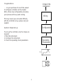
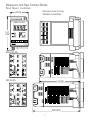
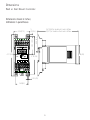
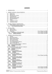
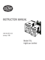
INSTRUCTION MANUAL
1262-IN-023-0-02
January 1998
Model 7SL
High/Low Limitrol
1/16 DIN FOUR DIGIT HIGH/LOW LIMITROL
Model 0 7 S L - 9 1
Field No. 1 2 3 4
5 6 7 8 9
-
00-0-00
10 1112 13 14 15
Field 1 through 4. BASE
07SL - Limitrol (High/Low Limit. Shipped as
high limit)
Field 7, 8. ALARMS, OPTIONS
00 -None
10 -One alarm - Relay Form A
11 -One alarm - Relay Form A, plus RS-485 and
one logic input.
Note: When code 11 is specified, instrument
length is 4.8 inches (122 mm)
Field 5. INPUT
9 - TC Types J, K, T, E, N, S, R, B, L, U, G, D
and Platinel II; and Pt 100 RTD;
0 to 20 mAdc and 4 to 20 mAdc
0 to 60 mVdc and 12 to 60 mVdc
0 to 5 Vdc or 1 to 5 Vdc
0 to 10 Vdc or 2 to 10 Vdc
Field 9. POWER SUPPLY
3 - 100 to 240 Vac
5 - 24 Vac/Vdc
Field 10. Mounting
0 - Panel Mount
R - Wall or Rail Mount
Note: All inputs are factory calibrated and
selectable by jumper. Factory set at Type J.
Field 6. OUTPUT (High/Low Limit)
1 - Relay (Form C)
Fields 11 through 15. RESERVED
2
Congratulations
U npack th e
In strum en t
. . . on your purchase of one of the easiest
to configure controllers on the market.
After a three step configuration procedure,
your process will be up and running.
W irin g
If for any reason you encounter difficulty
with the controller set-up, please call your
supplier.
Guide to Simple Set-up
Co nfig uratio n
To set-up the controller, only four steps are
required:
1. Wire the instrument.
2. Configure the instrument.
3. Check the operating mode parameters.
O perating
Param eters
SV
3
Contents
Mounting Requirements ...................................... 5
Panel Mount Controller --------------------- 5
Mounting Requirements ...................................... 6
Wall or Rail Mount Controller -------------- 6
Dimensions and Rear Terminal Blocks ................ 7
Panel Mount Controllers ------------------- 7
Dimensions ......................................................... 9
Wall or Rail Mount Controller -------------- 9
Wiring Guidelines .............................................. 10
Panel Mount Controllers ------------------ 10
Wiring Guidelines .............................................. 14
Wall or Rail Mount Controller ------------- 14
Preliminary Hardware Settings .......................... 20
Configuration Procedure ................................... 21
Operating Mode ................................................ 27
Error Messages ................................................. 32
General Specifications ...................................... 33
Calibration ......................................................... 37
Calibration Parameters -------------------- 38
Procedure ---------------------------------- 38
Maintenance...................................................... 44
APPENDIX A ..................................................... 45
Default parameters ------------------------ 45
APPENDIX B ..................................................... 47
Thermocouple Compensating Cable
Color Codes. ------------------------------- 47
CAUTION!
USE WIRE SUITABLE
FOR 75° MINIMUM
NOTES:
• For supply connections use 16 AWG or
larger wires rated for at least 75° C
• Use copper conductors only
• Class 2 wiring must be separated a
minimum of 1/4 inch from any class 1
conductor
IMPORTANT!
Terminal identification of the panel mount
controller is different from terminal identification of the wall/rail mount controller! This
manual contains wiring instructions for both
types of controllers.
Be sure to follow the instructions that pertain
to the controller you are using.
4
Mounting Requirements
The instrument can be mounted on a panel up to 15
mm (0.591 in) thick with a square cutout of 45 x 45
mm (1.772 x 1.772 in). For outline refer to Dimensions
and Panel Cutout.
Panel Mount Controller
Select a mounting location with the following
characteristics:
1) Minimal vibration.
2) An ambient temperature range between 0 and
50°C (32 and 122 °F).
3) Easy access to the rear of the instrument.
4) No corrosive gases (sulfuric gas, ammonia,
etc.).
5) No water or other fluid (i.e. condensation).
6) Relative humidity of 20% to 80% non
condensing.
Panel surface texture must be better than 248
microinches.
The instrument is shipped with a rubber panel gasket
(50 to 60 Sh). To assure the IP65 and NEMA 4
protection, insert the panel gasket between the
instrument and the panel as shown below.
Install the instrument as follows:
1) Insert the instrument in the gasket.
2) Insert the instrument in the panel cutout.
3) Pushing the instrument against the panel,
insert the mounting bracket.
4) Torque the mounting bracket screws between
0.3 and 0.4 Nm (2.66 and 3.54 lbf-in).
5) To insure NEMA 4X/IP65 protection, make sure
the instrument does not move within the
cutout .
B ra c ke t
Panel
G a sk e t
5
Mounting Requirements
RAIL MOUNTING
Use DIN rail in accordance with EN 50 022 (35 x 7.5
mm or 35 x 15 mm).
Wall or Rail Mount Controller
WARNING:
1) The correct functionality of these instruments
is guaranteed only if transport, storage,
installation, wiring, working condition and
maintenance are executed in compliance
with this manual.
2) The protection degree of these instruments is
equal to IP 20 (according to IEC529) and they
are connected to dangerous power lines, for
these reasons:
- installation, wiring and maintenance must
be executed by qualified personnel;
- all warnings contained in this manual must
be complied.
3) The safety requirements for Permanently
Connected Equipment say:
- a switch or circuit-breaker shall be
included in the building installation;
- It shall be in close proximity to the
equipment and easy to reach for the
operator;
- it shall be marked as the disconnecting
device for the equipment.
NOTE: a single switch or circuit-breaker can
drive more than one instrument.
4) Before to executing any operation on the
connections, disconnect the instrument from
the power line by the circuit breaker.
WALL MOUNTING
For wall mounting, use the (A) holes.
In this case it is advisable to use four M4
screws with a torque of 1Nm.
(A )
ºF
R ES ET
GENERAL ASSEMBLING INFORMATION
Select a cleaned location, easy to reach, where
minimum vibrations are present and the ambient
temperature is within 0 and 50 °C (32 and 122 °F).
These instruments can be mounted either on wall
or DIN rail.
AL M
6/
(A )
6
Dimensions and Rear Terminal Blocks
Panel Mount Controllers
Dimensions shown in inches;
millimeters in parenthesis
1 .8 9 (4 8)
B arber-C o l ma n
F
2 .4 7
(6 2.8 )
7 SL
Without RS-485
With RS-485
4 .1 3 (1 0 5)
4.80 (12 2)
7
PANEL CUTOUT
Dimensions shown in inches;
millimeters in parentheses
2.9 5 (7 5)
2.36 (60 )
1.77 2 + 0.024 , -0
(4 5 + 0.6, - 0)
1 .7 72
+ 0 .024, -0
(45 + 0 .6 , -0 )
8
Dimensions
Wall or Rail Mount Controller
Dimensions shown in inches;
millimeters in parentheses
5
(0 .20 in .)
5 .6 7 (1 44 ) fo r m o dels w ith se rial interf ace
5 (1 2 7) for m odels w itho u t se rial interf ace
0 .2 0 (5.)
1 .8 1 (4 6)
2 .2 6 (5 7.5 )
°F
4 .1 7 (1 06 .)
1 .89 (4 8)
RE SE T
AL M
3 .7 8 (9 6)
7 SL
0.1 8 (4.5 )
1.69 (4 3)
9
Wiring Guidelines
RTD INPUT -- Panel Mount Controller
Panel Mount Controllers
RTD
RTD
A) Measuring Inputs
NOTE: Any external components (like Zener diodes,
etc.) connected between sensor and input terminals
may cause errors in measurement due to excessive
and/or not balanced line resistance or possible
leakage currents.
TC Input
8
9
10
8
9
10
+ 10
RTD Input Wiring
NOTE:
1) Don’t run input wires with power cables.
2) Pay attention to the line resistance; a high line
resistance may cause measurement errors.
3) When shielded cable is used, it should be
grounded at one side only to avoid ground loop
currents.
4) Resistance of the 3 wires must be the same.
_ 9
Shield
+ 10
_ 9
LINEAR INPUT - Panel Mount Controller
Shield
10
Thermocouple Input Wiring
NOTE:
1) Do not run input wires with power cables.
2) For TC wiring use proper compensating cable,
preferably shielded (see Appendix B).
3) Shielded cable should be grounded at one end
only.
9
+
_
mA,
mV
or
V
Shield
mA, mV, and V Inputs Wiring
10
- Use an external dry contact capable of
switching 0.5 mA, 5 Vdc.
- The instrument needs 100 ms to recognize a
contact status variation.
- The logic inputs are NOT isolated from the
measuring input.
+
10
_
9
mA
mV
or
V
G
C.1) Relay Outputs Panel Mount Controller
NO - OUT 1
OUT 1
1
mA, mV and V Inputs Wiring
NOTE:
1) Don’t run input wires together with power
cables.
2) Pay attention to the line resistance; a high line
resistance may cause measurement errors.
3 ) When shielded cable is used, it should be
grounded at one side only to avoid ground loop
currents.
4) The input impedance is equal to:
Less than 5 Ω for 20 mAdc input
Greater than 1 MΩ for 60 mVdc input
Greater than 400 KΩ for 5 Vdc and 10 Vdc
input
C - OUT 1
Class 1
2
NC - OUT 1
3
OUT 2
Class 1
(Alarm)
C
6
NO
7
The OUT 1 contact rating is 3A/250V AC on
resistive load.
The OUT 2 contact rating is 2A/250V AC on
resistive load.
The number of operations is 1 x 10⁵ at specified
rating.
NOTES 1) To avoid electric shock, connect power
line at the end of the wiring procedure.
2 ) For power connections use No 16 AWG
or larger wires rated for at last 75 °C.
3) Use cupper conductors only.
4) Don’t run input wires with power cables.
All relay contacts are protected by varistor against
inductive load with inductive component up to 0.5 A.
B) Logic Input - Panel Mount Controller
Logic input
14
15
This input is used for remote acknowledgement
(reset).
Safety note:
- Do not run logic input wiring with AC power
cables.
11
The following recommendations avoid serious
problems which may occur, when relay outputs
are used with inductive loads.
Anyway the cable involved in relay output wiring
must be as far away as possible from input or
communication cables.
C.2) Inductive Loads
High voltage transients may occur switching
inductive loads.
Through the internal contacts these transients
may introduce disturbances which can affect the
performance of the instrument.
For all the outputs, the internal protection
(varistor) assures a correct protection up to 0.5 A
of inductive component.
D) Serial Interface
Panel Mounted Controllers
SERIAL INTERFACE
For units built with optional RS-485 communication
RS-485 interface allows to connect up to 30
devices with one remote master unit.
I
N
S
T
R
U
M
E
N
T
The same problem may occurs when a switch is
used in series with the internal contacts as
shown below:
C
R
POWER
LINE
LOAD
External Switch in Series with Internal Contact
C
(µF)
R
(Ω)
P.
(W)
OPERATING
VOLTAGE
<40 mA 0.047 100
<150 mA 0.1
22
<0.5 A
0.33
47
1/2
2
2
260 V AC
260 V AC
260 V AC
12
13
A/A'
A'/A
B/B'
B'/B
COMMON
M
A
S
T
E
R
RS-485 Wiring
In this case it is recommended to install an
additional RC network across the external contact
as shown above.
The value of capacitor (C) and resistor (R) are
shown in the following table.
LOAD
(mA)
11
The cable length must not exceed 9/10 mile (1.5
km) at 9600 baud.
NOTE: The following report describes the signal
sense of the voltage appearing across the
interconnection cable as defined by EIA for
RS-485.
a) The ” A ” terminal of the generator shall
be negative with respect to the ” B ” terminal
for a binary 1 (MARK or OFF) state.
b) The ” A ” terminal of the generator shall
be positive with respect to the ” B ” terminal
for a binary 0 (SPACE or ON)
12
I
N
S
T
R
U
M
E
N
T
I
N
S
T
R
U
M
E
N
T
11
12
3)
4)
5)
6)
Use copper conductors only.
Do not run input wires with power cables.
Polarity does not matter for 24 Vdc wiring.
The power supply input is NOT fuse
protected.
Please provide it externally.
Power supply
Type Current
Voltage
24 V AC/DC
T
500 mA
250 V
100/240 V AC
T
125 mA
250 V
When fuse is damaged, it is advisable to verify the
power supply circuit, so that it is necessary to
send back the instrument to your supplier.
7) Safety requirements for permanently
connected equipment:
- Include a switch or circuit-breaker in the
installation.
- Place switch in close proximity to the
equipment and within easy reach of the
operator.
- Mark the switch as the disconnecting
device for the equipment.
NOTE: A single switch or circuit-breaker can
drive more than one instrument.
8) When the NEUTRAL line is present, connect it
to terminal 4.
9) To avoid shock and possible instrument
damage, connect power last.
A'/A
A/A'
B'/B
B/B'
COMMON
13
M
A
S
T
E
R
11
12
13
RS-485 Wiring for Multiple Instruments
E) Power Line and Grounding Panel Mount Controllers
N, L2
4
5
POWER SUPPLY
100 to 240 Vac
24 Vac/Vdc
R (S,T), L1
N, L2
R (S,T), L1
NOTE:
1) Before connecting the power line, check that
the voltage is correct (see Model Number).
2) For supply connections use 16 AWG or larger
wires rated for at least 75 °C.
13
Wiring Guidelines
MEASURING INPUTS
N OTE S:
1) Any external components (like zener
barriers etc.) connected between
sensor and input terminals may cause
measurement errors due to excessive and/or not balanced line
resistance or possible leakage
currents.
2) The input accuracy is equal to +/- 0.2
% f.s.v. (**) +/- 1 dgt. @ 25 degrees
Celsius of ambient temperature.
(**) For TC input, the f.s.v. should be
referenced to the higher f.s.v. of the
TC selected.
Wall or Rail Mount Controller
Connections have to be executed when the
instrument is placed in its proper location.
Ou t 1
Ou t 2
T /C(a )
T /C (b)
T/C (a ): G, D, C , B , R, S
T/C (b ): J, K , L , N , T, E, U , P la ti ne l
TC INPUT
TC Type G, D, C, B, R and S
(Wall & Rail Mount)
Model 7SL Terminal Block
Without RS-485 or Logic Input
Ou t 1
Ou t 2
+ 15
- 14
T /C (b)
T /C(a )
D igi
S h ie ld
+ 15
T/C (a ): G, D, C , B , R, S
T/C (b ): J, K , L , N , T, E, U , P la ti ne l
- 14
S h ie ld
Model 7SL Terminal Block
With RS-485 and Logic Input
Input Wiring for TC
Type G, D, C, B, R and S
14
TC Type J, K, L, N, T, E, U and
Platinel (Wall & Rail Mount)
RTD INPUT (Wall & Rail Mount)
RTD
RTD
+ 15
- 11
S hie ld
+ 15
16
15
14
16
15
14
- 11
RTD Input Wiring
S hie ld
NOTE:
1) Don’t run input wires together with
power cables.
2) Pay attention to the line resistance; an
high line resistance may cause
measurement errors.
3) When shielded cable is used, it should
be grounded at one side only to avoid
ground loop currents.
4) The resistance of the 3 wires must be
the same.
Input Wiring for
TC Types J, K, L, N, T, E, U and Platinel
NOTE :
1) Do not run input wires with power
cables.
2) For T/C wiring use proper compensating cable, preferably shielded (see
appendix B).
3) When a shielded cable is used, it
should be connected to one side only.
15
LOGIC INPUT (Wall & Rail Mount Controllers with Serial Input)
LINEAR INPUT(Wall & Rail Mount)
15
S h ield
This input is used for remote alarm reset
when manual reset of alarm is selected.
mA,
mV
or
V
14
15
SAFETY NOTES:
1) Do not run logic input wiring together
with power cables.
2) Use an external dry contact capable of
switching 0.5 mA, 5 V DC.
3) The instrument needs 100 ms to
recognize a contact status variation.
4) The logic input is NOT isolated by the
measuring input.
m A,
mV
or
V
14
G
mA, mV and V Inputs Wiring
NOTE:
1) Do not run input wires together with
power cables.
2) Pay attention to the line resistance; a
high line resistance may cause
measurement errors.
3) When shielded cable is used, it should
be grounded at one side only to avoid
ground loop currents.
4) The input impedance is equal to:
< 5 ohms for 20 mAdc input
> 1 megohms for 60 mVdc input
> 400 kilo-ohms for 5 Vdc and
10 Vdc input
12
13
Logic Input Wiring
16
RELAY OUTPUTS
(Wall & Rail Mount)
All relay contacts are protected by varistor
against inductive load with inductive component up to 0.5 A.
1
N O - O UT 1
The following are recommendations avoid
serious problems which may occur, when
using relay output for driving inductive loads.
O UT 1
Class 1
2
C - O UT 1
INDUCTIVE LOADS
(Wall & Rail Mount)
N C - O UT 1
3
O ut 2
C lass 1
(Ala rm )
7
8
High voltage transients may occur switching inductive loads.
Through the internal contacts these transients may introduce disturbances which
can affect the instrument performance.
For all outputs, the internal protection (varistor) assures a correct protection up to 0.5 A
of inductive component.
C
NO
Relay Outputs Wiring
The contact rating of OUT 1 is 3A/250V ac
on resistive load. Contact rating of OUT 2 is
2A/250 Vac on resistive load. The number
of operations is 1 x 10⁵ at specified rating.
The same problems may occur when a
switch is used in series with the internal contacts as shown:
NOTES
1) To avoid electric shock, connect
power line at the end of the wiring
procedure.
2) For power connections use No 16
AWG or larger wires rated for at last
75 °C.
3) Use copper conductors only.
4) Do not run input wires with power
cables.
P ow er
Lin e
External Switch in Series
with Internal Contact
17
SERIAL INTERFACE
(Wall & Rail Mount)
In this case it is recommended to install an
additional RC network across the external
contact as shown. The value of capacitor
(C) and resistor (R) are shown in the following table:
P(W)
Op. V
1/2 260 Vac
2 260 Vac
2 260 Vac
5
6
Anyway the cable involved in relay output
wiring must be as fara away as possible
from input or communication cables.
4
5
6
B/B ’
B’/B
C o m m on
A/A’
A ’/A
B/ B ’
B ’/ B
Com mon
M A S TE R
C(µF) R(ohms)
0.047)
100
0.1
22
0.33
47
M A S TE R
Load
<40 mA
<150 mA
<0.5 A
RS-485 interface allows to connect up to 30
devices with one remote master unit.
A ’/A
4 A /A ’
4
5
6
RS-485 Wiring
The cable length must not exceed 9/10 mile
(1.5 km) at 9600 BAUD.
NOTE: The following report describes the
signal sense of the voltage appearing across
the interconnection cable as defined by
EIA for RS-485.
18
a) The ”A” terminal of the generator shall
be negative with respect to the ”B”
terminal for a binary 1 (MARK or OFF)
state.
b) The ”A” terminal of the generator shall
be positive with respect to the ”B”
terminal for a binary 0 (SPACE or
ON)
5) Do not run input wires with power
cables.
6) For 24 Vdc the polarity is not a care
condition.
7) The power supply input is not fuse
protected. Please, provide it externally.
Pwr Supply Type Current Voltage
24 Vac/ Vdc
T 500 mA
250 V
100/240 Vac
T 125 mA
250 V
When fuse fails, check instrument for
component damage. It is advisable to
verify the power supply circuit, so it
may be necessary to send the
instrument back to your supplier.
8) The safety requirements for Permanently Connected Equipment say: a
switch or circuit-breaker shall be
included in the building installation; It
shall be in close proximity to the
equipment and within easy reach of
the operator; it shall be marked as the
disconnecting device for the equipment.
NOTE: a single switch or circuitbreaker can drive more than one
instrument.
9) When neutral line is present, connect it
to terminal 9.
POWER LINE WIRING
(Wall & Rail Mount)
N, L2
9
10
100 to 240 Vac rms, 50/60 Hz
or 24 Vac/Vdc
R (S,T), L1
N, L2
R
(S,T)
L1)
Power Line Wiring
NOTES :
1) Before connecting the instrument to
the power line, make sure that line
voltage corresponds to the description on the identification label.
2) To avoid electric shock, connect
power line at the end of the wiring
procedure.
3) For supply connections use No 16
AWG or larger wires rated for at last
75 °C.
4) Use copper conductors only.
19
Preliminary Hardware Settings
Limitrol without RS-485
1) Remove the instrument from its case.
2) Set J106 according to the desired input type as
shown in the following figure.
INPUT
TYPE
1-2
TC-RTD close
60 mV
close
5V
10 V
20 mA
open
open
open
3-4
open
open
J106
5-6
open
open
7-8
open
open
close
open
open
open
close
open
open
open
close
V101
Limitrol with RS-485
2
4
6
8
1
3
5
7
J106
V101
20
2
4
6
8
1
3
5
7
J106
Configuration Procedure
The following is a complete list of parameters. The
lower display will show the parameter code (L1 to
d1) and the upper display will show the selection
code or numerical value. No timeout is applied in the
configuration mode.
CONFIGURATION KEY FUNCTIONS
RESET In Configuration Mode, it is used only to
scroll back parameters without to memorize a new parameter value.
Used in Configuration Mode to decrease
the parameter value.
Used in Configuration Mode to increase
the parameter value.
FUNC Used to memorize the new parameter
value and go to the next parameter.
+
Loads the default parameters.
+ FUNC or + FUNC
Increases/decreases values at a higher
rate when modifying parameters.
+ RESET or
+ RESET
Jumps to the Maximum or Minimum parameter value when modifying parameters.
L1 = Serial Interface Protocol
(Skipped if option is not available.)
OFF = No serial interface
nbUS= Modbus
jbUS = Jbus
L2 = Serial Link Device Address
(Skipped if option is not available or L1 = OFF)
From 1 to 255
NOTE: EIA standard allows no more than 31 device
connected by one RS-485.
CONFIGURATION PROCEDURE
1) Remove the instrument from its case.
2) Open switch V101 (See illustrations under
“Preliminary Hardware Settings.”)
3) Re-insert the instrument in its case.
4) Switch on power to the instrument.
The upper display will show COnF.
NOTE : If "CAL" indication will be displayed,
press immediately the s pushbutton and
return to the configuration procedure.
5) Press the “ ” key and the lower display will
show the firmware version.
L3 = Baud Rate for Serial Link
(Skipped if option is not available or L1 = OFF)
Set value from 600 to 19200 baud.
(19200 baud is shown on display as 1920)
L4 = Byte Format for Serial Link
(Skipped if option is not available or L1 = OFF)
8E = 8 bits + even parity
8O = 8 bits + odd parity
8
= 8 bits without parity
Press the "FUNC" key to start the configuration
procedure with the first parameter (L1).
21
r 1 =Input Type
0 = TC J
1 = TC K
2 = TC T
3 = TC E
4 = TC N
5 = TC S
6 = TC R
7 = TC B
8 = TC L
9 = TC U
10 = TC G
11 = TC D
12 = TC C
13 = TC Plat. II
14 = RTD Pt 100
15 = Linear
16 = Linear
17 = Linear
18 = Linear
19 = Linear
20 = Linear
21 = Linear
22 = Linear
23 = TC J
24 = TC K
25 = TC T
26 = TC E
27 = TC N
28 = TC S
29 = TC R
30 = TC B
31 = TC L
32 = TC U
33 = TC G
34 = TC D
35 = TC C
36 = TC Plat. II
37 = RTD Pt100
and Range
From -100
From -100
From -200
From -100
From -100
From
-50
From
-50
From
0
From -100
From -200
From
0
From
0
From
0
From
-100
From -200
From
0
From
12
From
0
From
4
From
0
From
1
From
0
From
2
From -150
From -150
From -330
From -150
From -150
From
-60
From
-60
From
32
From -150
From -330
From
0
From
0
From
0
From
-150
From
-330
Value
to 1000
to 1370
to
400
to
800
to 1400
to 1760
to 1760
to 1820
to
900
to
600
to 2300
to 2300
to 2300
to 1400
to
850
to
60
to
60
to
20
to
20
to
5
to
5
to
10
to
10
to 1830
to 2500
to
750
to 1470
to 2550
to 3200
to 3200
to 3300
to 1650
to 1110
to 4170
to 4170
to 4170
to 2550
to 1560
r2 = Decimal Point Position
(Available only for linear range r1 = 15 to 22)
_ _ _ _ . = No decimal
_ _ _ . _ = One decimal place
_ _ . _ _ = Two decimal places
_ . _ _ _ = Three decimal places
°C
°C
°C
°C
°C
°C
°C
°C
°C
°C
°C
°C
°C
°C
°C
mV
mV
mA
mA
V
V
V
V
°F
°F
°F
°F
°F
°F
°F
°F
°F
°F
°F
°F
°F
°F
°F
r3 = Initial value of the readout scale
(Available only for linear range r1 = 15 to 22)
Range: From -1999 to 9999
r4 = final value of the readout scale
(Available only for linear range r1 = 15 to 22)
Range: From -1999 to 9999
r5 = Offset Adjustment
Range: From -500 to 500
Offset value algebraically added to the measured
value.
r6 = Time constant of the filter applied to the
displayed value
Range: From 0 (filter OFF) to 8 seconds.
(First order filter with selected time constant.)
r7 = Alarm action on input fault.
When the instrument detects an input failure
condition, the alarm will operate as in presence
of:
uP = as in presence of the full scale value.
doun = as in presence of the initial scale value.
C1 = Type of limit action
Hi. = High limit (for heating process)
Lo. = Low limit (for cooling process)
Hi.Lo = High and low limit (for special process)
22
C2 = Rearming Mode
O = Acknowledgements rearm (reset) the limiter
(and restart the process) only if the condition
which generated the shutdown status no longer
exists (points A and C of the Example 1). It do
not generate any effect if the condition which
generated the shutdown status still exists (point
B of the Example 1).
I = Acknowledgements enable the automatic
rearmament (reset) of the limiter if the
condition which generated the shutdown
status still exists (point B of the Example 2).
(The instrument rearms (reset) automatically
when the condition which generated the
shutdown status no longer exists).
When C2 =0 and OUT 1 is OFF, RESET LED is ON.
When C2 = 1 one of the following condition may
occur:
- if no acknowledgement has been made, OUT 1
is OFF and the RESET LED is flashing;
- if the acknowledgement has been made but the
condition which generated the shutdown status
still exists, OUT 1 is OFF and the RESET LED
is steady ON.
Notes about limiter function
The relay of the output 1 operates in fail-safe
mode (relay de-energized during shutdown
condition) and latching mode.
The length of the shutdown condition and max/min
measured values are stored in memory and available for viewing until the next shutdown condition
occurs. These informations are lost at power down.
During a shutdown condition the max/min
measured values are continuously updated and
can be monitored.
The shutdown condition can be stored in permanent
memory (see C4).
Acknowledgment can be performed by pressing the
RESET key, by momentarily closing the external dry
contact or by a command from the serial link.
The OUT 1 turns OFF when:
- C1 = Hi and the measured value is greater
than limiter threshold [“Su” parameter (see
Operative parameters”)] or
- C1 = LO and the measured value is less than
limiter threshold [“Su” parameter (see
Operative parameters”)] or
- C1 = HiLO and the measured value is greater
than “Su” parameter (see Operative parameters”) or less than “S1” parameter (see
Operative parameters”).
The Out 1 remains OFF until the condition which
generated the shutdown, no longer exists and the
acknowledge action has been performed.
Example 1 - C1 = Hi and C2 = O
The upper display flashes during a shutdown and
returns to a steady display when the shutdown
condition no longer exists.
A, B, C = Acknowledgment actions.
NOTE: Acknowledgment B has no effect.
23
P2 = Alarm configuration
(Skipped if option is not available or P1 = none)
H.A. = High alarm with automatic reset
L.A. = Low alarm with automatic reset
H.A.Ac = High alarm with automatic reset and
"Silence" function.
L.A.Ac =Low alarm with automatic reset and
"Silence" function.
H.L. = High alarm with manual reset
L.L. = Low alarm with manual reset
Example 2 - C1 = Hi and C2 = 1
NOTE:
1 ) For band alarm, H.A./H.A.Ac/H.L. signifies
outside band alarm, while L.A./ L.A.Ac/L.L.
signifies inside band alarm.
2 ) The "Silence" function allows the manual reset
of the alarm even if the alarm condition is still
in progress.
A, B = Acknowledgment actions.
C3 = Rearm at Power-up
Auto = Automatic rearm
n An = Manual rearm
C4
0
1
Example for P2 = H.A.
= Shutdown memory
= The shutdown condition will be saved (at
next power up it will be reactivated)
= The shutdown condition will be lost in
case of power down
C5 =Time Constant of the Filter applied
to the Measured Value for Limit
Action.
Range: From 0 (filter OFF) to 8 seconds
Note: First order filter with selected time constant.
* Alarm Status:Relay energized (P3 = dir)
Relay de-energized (P3 =rEV)
P 1 = Alarm Function
(Skipped when the option is not available)
nonE = Not provided
AL.P = Process alarm
AL.b = Band alarm
AL.d = Deviation alarm
When C1 = Hi.Lo, “AL.b” and “AL.d” are not
available.
24
Example for P2 = H.A.A.c
P3 = Alarm Action
(Skipped if option not is available or P1 = none)
dir = Direct action
(Relay energized in alarm condition)
rEV = Reverse action
(Relay energized in non-alarm condition)
P4 =
Alarm Standby (mask) Function
(Skipped if option is not available or P1= none)
OFF =
Standby function disabled
On =
Standby function enabled
If the alarm is programmed as band or deviation,
this function masks the alarm condition at start up
and after a “Su” (limit threshold) changement until
the process variable reaches the alarm threshold,
plus or minus hysteresis. This standby function
masks a Process Alarm condition at start up until
the process variable reaches the alarm threshold
plus or minus hysteresis.
* Alarm Status: Relay energized (P3 = dir)
Relay de-energized (P3 =rEV)
Example for P2 = H.L.
PF = Time Constant of the Filter applied to the
Measured Value for Alarm Action
(Skipped if option is not available or P1 = none)
Range: From 0 (filter OFF) to 8 seconds
(First order filter with selected time constant.)
* Alarm Status:Relay energized (P3 = dir)
Relay de-energized (P3 =rEV)
25
n1 = Safety Lock
0 = UNLOCKed. The device is always
UNLOCKed and all parameters can be
modified.
l
= LOCKed. The device is always LOCKed
and no parameters can be modified
From 2 to 9999 = This number is a password, to
be used in run time (see “nn”), to LOCK/
UNLOCK the device.
t1 = Timeout Selection
tn10 =
10 second timeout
tn30 =
30 second timeout
d1 = Digital Input (contact closure)
(This is a read only parameter)
Enb =
Digital input enabled
dlS =
Digital input disabled
(The digital input is used as a remote
Acknowledgment .)
The configuration procedure is now complete.
The display will show "COnF".
26
Operating Mode
5) The upper display shows the maximum
measured value detected during the last
shutdown condition while the lower display
shows "Ph.". If no shutdown condition was
detected, the upper display will show “- - - -”.
This information is not available if C1 = HI.Lo.
The information is lost at power down and at
powerup the device will display the process
variable.
1) Remove the instrument from its case.
2) Set switch V101 to the closed position. (See
illustrations at “Preliminary Hardware
Settings”).
3) Re-insert the instrument in its case.
4) Switch on the instrument.
Normal Display Mode
On powerup the device starts in the "Normal Display
Mode."
NOTE: When the shutdown condition was
generated by an input fault condition, the upper
display will indicate m .Err .
By pressing the or key, it is possible to change
the displayed information; therefore, one of the
following display modes can be selected:
6) The upper display shows the minimum
mesured value detected during the last
shutdown condition while the lower display
shows "PL.” If no shutdown condition was
detected, the upper display will show “- - - -”.
This information is not available if C1 = Hi.
The information is lost at power down and at
powerup the device will display the process
variable.
1) The upper display shows the measured value
while the lower display shows the "Pu"
(Process variable).
If this display was active at power down, it will
be active at powerup.
2) The upper display shows the limiter threshold
while the lower display shows "Su." If this
display was active at power down, it will be
active at powerup.
3) The upper display shows the second limiter
threshold while the lower display shows "S1."
This information is available only if C1 = Hi.Lo.
If this display was active at power down, it will
be active at powerup.
4) The upper display shows the total time
(hh.mm) of the last shutdown condition while
the lower displays shows “t.” If no shutdown
condition was detected, the upper display will
show “- - - -”. The information is lost at
power down and at powerup the device will
display the process variable.
NOTE: When the shutdown condition was
generated by an input fault condition, the
upper display will indicate m .Err
If, at power off, the device was in shutdown
condition and shutdown memoy function is
selected (C4 = 0), and/or it was programmed for
manual reset at startup (C3 = 1), then at the next
power up the lower display will be flashing.
27
Indicators
“RESET“ =Indicates control output 1 status as
follows:
a) When C2 parameter has been
configured equal to 0,
LED ON when Output 1 is OFF
LED OFF when Output 1 is ON
b) When C2 parameter has been
configured equal to 1,
LED flashes when Output 1 is OFF
LED ON when Output 1 is OFF and
acknowledged
LED OFF when Output is ON
“ALM” = Indicates alarm status as follows:
- Flashes when alarm is ON
- ON when alarm has been resetted but
the alarm condition is still present.
- OFF when alarm is OFF
“REM” = Indicates the remote status of the
instrument.
- Flashes when instrument is in remote
mode.
- OFF when instrument is in local mode.
“RESET”= Press and hold for 1 second to rearm
(reset) the limiter.
+ FUNC or + FUNC
Increases/decreases values at a higher
rate when modifying parameters.
+ RESET or
+ RESET
Jumps to the Maximum or Minimum
parameter value when modifying
parameters.
Operative Parameter Display Mode
The "FUNC" key initiates the Operative Parameter Display Mode when pressed for less than 10
seconds in the "Normal Display Mode."
The lower display shows the parameter code while
the upper display shows the parameter value or
status. The value of the selected parameter can be
modified with the and keys.
Press the "FUNC" key again to store the new
value and advance to the next parameter.
Key Functions in Normal Display Mode
“FUNC” = By pressing it, the display changes from
“Normal Display Mode” to “Operative
Parameter Display Mode.”
= Pressing it for more than ten seconds
initiates the Lamp Test. During the Lamp
Test the device functions normally while
all display segments and LED's are lit
with a 50% duty cycle. No timeout is
applied to a lamp test.
Press the "FUNC" key again to end the
Lamp Test.
" " or “ " = By pressing these keys it is
possible to change the displayed
information. See “Normal Display
Mode.”
If no keys are pressed within the timeout period
(see t1), the instrument will automatically return to
the "Normal Display Mode" in the previous display
and any modification of the last displayed
parameter will be lost.
All parameters (except
) can be modified only
when the device is UNLOCKed.
The LOCK/UNLOCK status can be selected in
configuration using “n1” parameter or during the
operating mode with the “nn” parameter
(password).
28
To switch from LOCKED to UNLOCKED, assign
to the “nn” parameter a value equal to the “n1”
parameter setting. To switch from UNLOCKED to
LOCKED, assign to the “nn” parameter any
number other than the n1 parameter setting.
When the device is in remote mode (the serial link
controls the device) no parameters can be modified.
nn
Software Key
(Skipped if n1 = 0 or 1)
ON = the device is LOCKED.
OFF = the device is UNLOCKED.
When it is desired to switch from LOCK
to UNLOCK condition, set a value equal
to “n1” parameter.
When it is desired to switch from
UNLOCK to LOCK condition, set a value
different from “n1” parameter.
Su
Limiter Threshold
Range: Span limits (From "S1" to full scale
value when C1 = Hi.Lo)
S1
Second Limiter Threshold
(Available when C1 = Hi.Lo)
Range: From initial scale value to "Su"
HS
Limiter Hysteresis
Range: From 0.1% to 10.0% of the
input span or 1 LSD
AL
Alarm Threshold (optional)
(Available only if the option is fitted and
P1= AL.P, AL.b or AL.d.)
Ranges:
span limits for process alarm (P1 = AL.P)
from 0 to 500 for band alarm (P1 = AL.b)
from -500 to 500 for deviation alarm
(P1 = AL.d)
HA
Alarm Hysteresis (optional)
(Available only if the option is fitted and
P1 = AL.P, AL.b or AL.d)
Range: From 0.1% to 10.0% of the input
span or 1 LSD.
Key Functions in
Operative Parameter Display Mode
FUNC
=
Pressing the “FUNC” key, the
instrument stores the new setting
(if changed) and goes to the next
parameter.
or
=
Changes the setting of the
selected parameter.
RESET
=
Press and hold for more than 1
second for limiter rearmament.
OPERATING PARAMETERS
Some of the following parameters may not appear,
depending on the configuration.
Lower Description
Display
Manual reset of the alarm.
(Available only if P1 = AL.p, AL.b or AL.d)
ON = Starts the manual reset of the alarm
OFF = Do not start the alarm reset.
Select ON and press the FUNC key in
order to reset the alarm.
After a manual reset of the alarm the
instrument returns in Normal Display Mode.
29
Limiter function
The relay of the output 1 operates in fail-safe
mode (relay de-energized during shutdown
condition) and latching mode.
contact or by a command from the serial link.
The length of the shutdown condition and max/min
measured values are stored in memory and available
for viewing (see “Normal Display Mode”) until the next
shutdown condition occurs.
These informations are lost at power down.
The OUT 1 turns OFF when:
- The instrument is configured as a high limiter
(C1 = Hi) and the measured value is greater
than limiter threshold [“Su” parameter (see
Operative parameters”)] or
- The instrument is configured as a low limiter
(C1 = LO) and the measured value is less
than limiter threshold [“Su” parameter (see
Operative parameters”)] or
- The instrument is configured as a high/low
limiter (C1 = HiLO) and the measured value is
greater than “Su” parameter (see Operative
parameters”) or less than “S1” parameter (see
Operative parameters”).
The Out 1 remains OFF until the condition which
generated the shutdown, no longer exists and the
acknowledge action has been performed.
During a shutdown condition the max/min measured values are continuously updated and can be
monitored.
Example 1 - C1 = Hi and C2 = O
The upper display flashes during a shutdown and
returns to a steady display when the shutdown
condition no longer exists.
Example 2 - C1 = Hi and C2 = 1
When the OUT 1 is OFF the RESET LED is ON [if the
selected rearming mode is equal to 0 (C2 = 0)] or
flashes [if the selected rearming mode is equal to 1
(C2 = 1)].
When the selected rearming mode is equal to 1
(C2 = 1) the RESET LED is steady ON when
OUT 1 is OFF and acknowledged.
The shutdown condition can be stored in permanent
memory (see C4).
Acknowledgment can be performed by pressing the
RESET key, by momentarily closing the external dry
30
Serial LInk (optional)
The device can be connected to a host computer via
serial link.
Alarm functions
(Skipped if option is not available or P1 = none)
The alarm can be programmed as:
- process alarm
- band alarm
- deviation alarm.
Band and deviation alarms are referred to the
limiter threshold and are possible only if an high
limiter or a low limiter function has been selected.
For all the alarm types, it is possible to select
automatic or manual reset or the “Silence”
function.
The "Silence" function is a typical function of the
alarm annunciators (see ISA “Alarm annunciator
operational sequence”) and it is usually applied to
audible alarm indications (horn). This function
allows the manual reset of the alarm even if the
alarm condition is still in progress.
The host can put the device in LOCAL (parameters
are controlled via keyboard) or in REMOTE (functions and parameters are controlled via serial link).
REMOTE is shown by the decimal point to the
left of "REM" which is on the right side of the
numeric display.
Via serial link it is possible to read and/or to modify
all the operative and configuration parameters.
The following conditions must apply to implement
this function:
1) Configure parameters L1 through L4 with the
front keyboard
2) The device must be in the Operating mode.
It is also possible to assign to the alarm a stand
by (mask) function.
If the alarm is programmed as band or deviation
alarm, this function masks the alarm condition
after a safety threshold change or at the
instrument start-up until process variable reaches
the alarm threshold plus or minus hysteresis. If
the alarm is programmed as a process alarm, this
function masks the alarm condition at instrument
start-up until process variable reaches the alarm
threshold plus or minus hysteresis.
Graphic example of the alarm behaviour are
shown at pages 12 and 13.
31
Error Messages
Error Messages
On powerup, the instrument performs a self-diagnostic test. When an error is detected, the lower
display shows an "Er" indication while the upper
display shows the code of the detected error.
Overrange, Underrange and
Sensor Break Indications
This device detects input fault conditions.
(OVERRANGE, UNDERRANGE OR SENSOR
BREAK). When the process variable exceeds the
span limits an OVERRANGE condition will appear
as:
Error List
100
Error in EEPROM writing
150
Short circuit on CPU's outputs
200
Error on "protect register" in EEPROM
XXX
Configuration parameter error.
301
Error on calibration of selected input.
307
rj input calibration error.
400
Error on operative parameters.
500
Error on autozero measurement.
502
Error on reference junction measurement.
510
Error during calibration procedure.
An UNDERRANGE condition will appear as:
Dealing with Error Messages
1) When a configuration parameter error is
detected, repeat the configuration procedure of
that specific parameter.
2) If an error 400 is detected, simultaneously
press the t and s keys to load the default
parameters and then repeat the control
parameter setup.
3) For all other errors, contact your
Service Representative.
A sensor break is signaled as "OPEn”. On the mA/
V input, a sensor break can be detected only when
the range selected has a zero elevation (4/20 mA,
12/60 mV, 1/5 V or 2/10 V.)
On the RTD input "shrt" is signalled when input
resistance is less than 15 Ω (short circuit sensor
detection).
This device detects reference junction errors or
errors on the internal autozero measurement. When
a fault is detected the output goes OFF and the
alarm assumes an upscale/downscale reading in
accordance with r7.
32
General Specifications
Safety requirements:
This instrument is marked CE.
Therefore, it is conforming to council directives
73/23/EEC and 93/68/EEC (reference harmonized
standard EN 61010-1).
Installation cathegory: II
D/A conversion: dual slope integration.
Sampling time :
- for linear inputs = 250 ms.
- for TC or RTD inputs = 500 ms.
Display updating time: 500 ms.
Resolution: 30000 counts.
Temperature Drift
- Less than 200 ppm/°C of full span for mV and
TC ranges 0, 1, 3, 4, 8, 13, 23, 24, 26, 27, 31,
36 (CJ excluded).
- Less than 300 ppm/°C of full span for mA, V and
TC ranges 10, 11, 12, 33, 34, 35 (CJ excluded)
- Less than 400 ppm/°C of full span for RTD and TC
range 9, 32 (CJ excluded).
- Less than 500 ppm/°C of full span for TC ranges
2, 5, 6, 25, 28, 29 (CJ excluded).
- Less than 600 ppm/°C of full span for TC ranges
7, 30.
NOTE: Precision and drift guaranteed (for
T>300°C/570°F).
Accuracy: + 0.2% f.s.v. @ 25 °C (77 °F) and
nominal power supply voltage.
Operative temperature: from 0 to +50 °C (32 to
122 °F).
Storage temperature: from -20 to +70 °C (-4 to
158 °F).
Humidity: from 20% to 85 % RH not
condensing.
Case: Polycarbonate grey case
Self extinguishing degree: V-0 according to UL.
Front protection - designed and tested for IP 65 (*)
and NEMA 4X (*) for indoor locations (when panel
gasket is installed).
(*) Test were performed in accordance with IEC
529, CEI 70-1 and NEMA 250-1991 STD.
Installation: panel mounting.
Rear terminal board: 15 screw terminals (screw
M3, for cables from ø 0.25 to ø 2.5 mm2 or from
AWG 22 to AWG 14 ), connection diagram and
safety rear cover.
Dimensions: 48 x 48 mm (according to DIN
43700); depth
- 122 mm for models with RS-485.
- 105 mm for models without RS-485
Weight: 250 g. max. (8.75 oz.).
Power supply : (switching mode) from 100 to
240 V AC. 50/60 Hz (+10 % to -15 % of the
nominal value) or
24 V DC/AC (+10 % of the nominal value).
Power consumption: 8 VA.
Insulation resistance: > 100 MΩ according to
IEC 1010-1.
Isolation voltage: 1500 V r.m.s. according to IEC
1010-1.
Common mode rejection ratio:
120 dB @ 50/60 Hz.
Normal mode rejection ratio: 60 dB @ 50/60 Hz.
Electromagnetic compatibility:
This instrument is marked CE.
Therefore, it is conforming to council directive 89/
336/EEC (reference harmonized standard EN50081-2 and EN-50082-2).
33
INPUTS
B) RTD (Resistance Temperature Detector)
Input: for RTD Pt 100 Ω, 3 wire connection.
Input circuit: current injection.
°C/°F selection: via front pushbuttons or serial link.
Line resistance: automatic compensation up to 20
Ω/wire with no measurable error.
Calibration: according to DIN 43760
Burn out : The instrument detect the open condition
of one or more wires. It is able to detect also the
short circuit of the sensor.
A) THERMOCOUPLE
Type : J, K, T, E, N, S, R, B, L, U, G(W), D(W3),
C(W5), Platinel II, °C/°F selectable.
External resistance: 100 Ω max, maximum
error 0.1% of span.
Burn out: It is shown as an overrange condition
(standard). It is possible to obtain an underrange
indication by cut and short.
Cold junction: automatic compensation from 0 to
50 °C.
Cold junction accuracy : 0.1 °C/°C
Input impedance: > 1 MΩ
Calibration : according to IEC 584-1 and DIN
43710 - 1977.
STANDARD RANGES TABLE
T/C
Ranges
type
J 0
K 1
T 2
E 3
N 4
S 5
R 6
B 7
L 8
U 9
G(W) 10
D(W3) 11
C(W5) 12
P.(*) 13
-100 / 1000
-100 / 1370
-200 / 400
-100 / 800
-100 / 1400
-50 / 1760
-50 / 1760
0 / 1820
-100 / 900
-200 / 600
0 / 2300
0 / 2300
0 / 2300
-100 / 1400
°C
°C
°C
°C
°C
°C
°C
°C
°C
°C
°C
°C
°C
°C
23
24
25
26
27
28
29
30
31
32
33
34
35
36
-150 / 1830
-150 / 2500
-330 / 750
-150 / 1470
-150 / 2550
-60 / 3200
-60 / 3200
32 / 3300
-150 / 1650
-330 / 1110
0 / 4170
0 / 4170
0 / 4170
-150 / 2550
STANDARD RANGES TABLE
Input
Ranges
type
°F
°F
°F
°F
°F
°F
°F
°F
°F
°F
°F
°F
°F
°F
RTD Pt 100 W
14
- 200 / 850
°C
DIN 43760
37
- 330 / 1560
°F
C) LINEAR INPUTS
Read-out: keyboard programmable between
-1999 and +9999.
Decimal point: programmable in any position
Burn out: the instrument shows the burn out
condition as an underrange condition for 4-20
mA, 1-5 V and 2-10 V input types.
It shows the burn out condition as an underrange
or an overrange condition (selectable by
soldering jumper) for 0-60 mV and 12-60 mV
input types. No indication are available for 0-20
mA, 0-5 V and 0-10 V input types.
(*) P. equal to Platinel II
34
STANDARD RANGES TABLE
Input type
impedance
15
16
17
18
19
20
21
22
0 - 60 mV
12 - 60 mV
0 - 20 mA
4 - 20 mA
0- 5 V
1- 5 V
0 - 10 V
2 - 10 V
OUTPUTS
Accuracy
Output updating time :
- 250 ms when a linear input is selected
- 500 ms when a TC or RTD input is selected.
> 1 MΩ
<5Ω
OUTPUT 1
Type: relay SPDT contact .
Contact rated: 3 A at 250 V AC on resistive load.
Function: Safety limiter output.
Action: reverse (fail-safe).
0.2 % + 1 digit
@ 25°C
> 400 kΩ
(77 °F)
> 400 kΩ
OUTPUT 2
Type: relay SPST contact .
Contact rated: 2 A at 250 V AC on resistive load.
Function: Alarm output
Action: direct/reverse programmable by front
keyboard.
D) LOGIC INPUTS
This instrument is provided of 1 logic input used
for remote acknowledgement.
NOTES
1) Use an external dry contact capable of
switching 0.5 mA, 5 V DC.
2) The instrument needs 100 ms to recognize a
contact status variation.
3 ) The logic inputs are NOT isolated by the
measuring input.
ALARM
Action: Direct or reverse acting.
Alarm functions: configurable as process alarm,
band alarm or deviation alarm.
Alarm reset: automatic reset, manual reset or
"Silence" function is programmable.
Stand by (mask) alarm: the alarm can be
configured with or without stand by (mask)
function.
Process alarm:
Operative mode : High or low programmable.
Threshold: programmable in engineering unit within
the readout span.
Hysteresis: programmable from 0.1 % to 10.0 % of
the readout span.
35
Band alarm
Operative mode: Inside or outside band
programmable.
Threshold: programmable from 0 to 500 units.
Hysteresis : programmable from 0.1 % to 10.0 % of
the readout span.
Deviation alarm
Operative mode : High or low programmable.
Threshold : programmable from - 500 to +500
units.
Hysteresis : programmable from 0.1 % to 10.0 % of
the readout span.
SERIAL COMMUNICATION INTERFACE
(OPTION)
Type: RS-485
Protocol type: MODBUS or JBUS.
Baud rate: programmable from 600 to 19200
BAUD.
Byte format: 8 bit.
Parity: even, odd or none programmable.
Stop bit: one.
Address: from 1 to 255.
Output voltage levels: according to EIA
standard.
36
Calibration
d) Minimum warm up time should be at least
20 minutes.
e) Operate as much as possible in a noise
free environment.
f) During calibration, connect one input at a
time to the rear terminal block.
g) Before input calibration, the specific
settings described in the Preliminary
Hardware Settings section must be made.
h) Use calibrators with the following:
Accuracy
Current Input:
±0.025% output
±0.0025% range
±0.01 microamp
Voltage Input:
±0.005% output
±0.001% range
±5 microvolt
TC Input:
±0.005% output
±0.001% range
±5 microvolt
RTD Input:
±0.02%
±0.0025 ohm/decade
Reference Junction Compensation:
better than 0.1°C
mA output: better than ±0.1% of the
readout ±2 microamp
Resolution
Current Input: 0.5 microamp
Voltage Input: 100 microvolt
TC Input:
1 microvolt
RTD Input:
10 milliohm
Ref. Jct. Compensation: better than 0.1°C
mA output
1 microamp
Calibration parameters are logically divided into
groups of two parameters each – initial scale
value and final scale value. A calibration check
is provided after entering the values of each
group. A calibration check can be initiated without making an entry: press the FUNC key to advance to the desired calibration check. The lower
display will show the parameter code (t., rJ., etc.)
and the upper display will show “on” or “off.”
Press the s or t key to select on or off.
To go to the next parameter without modifying
the calibration, press the FUNC key when the
displays shows “off.” To return the previous parameter without modifying the calibration, press
the MAN key.
To set the parameter calibration, press the FUNC
key when the display shows “on.” The display
will blank, and only the decimal point of the LSD
of the lower display will be lit during the calibration step.
Before beginning calibration, be sure internal
switch V101 is open (see "Preliminary Hardware
Settings").
General Guidelines
a) Instrument should be mounted in its case
in order to keep internal temperature
constant.
b) Ambient temperature should be stable.
Avoid drift due to air conditioning or other
mechanical devices.
c) Relative humidity should not exceed 70%.
37
Calibration Parameters
Following is a complete list of calibration symbols:
CodeParameter
tL
TC/mV Input Minimum Range Value
tH TC/mV Input Maximum Range Value
t.
TC/mV Input Check
rJ
Reference Junction Compensation
rJ. Reference Junction Compensation Check
(in 1/10°C; Reset LED lit)
PL RTD Input Minimum Range Value
PH RTD Input Maximum Range Value
P.
RTD Input Check
AL Current Input Minimum Value (0 mA)
AH Current Input Maximum Value (20 mA)
A.
Current Input Check
nL 5 Volt Input Min. Range Value (0 V)
nH 5 Volt Input Max Range Value (5 V)
n.
5 Volt Input Check
UL 10 Volt Input Minimum Value (0 V)
UH 10 Volt Input Maximum Value (10 V)
U. 10 Volt Input Check
Use the s and t keys to select between ON
and OFF. To go to the next parameter without
modifying the calibration, press the FUNC key
when the display shows “OFF” .
tL TC/mV input minimum range value
a) Perform the preliminary hardware settings.
Connect the calibrator and instrument as
shown below.
P an el
m o un ted
co n tro ller
W a ll o r
R a il
m o un te d
co n tro ller
10
9
15
14 for Ty pe s G , D , C , B , R , S
11 for Ty pe s J, K , L, N , T, E , U , Platin el
Procedure
Set the internal DIP switches as explained in the
Preliminary Hardware Settings section of this
manual. Perform calibration procedures according the jumpers positions, otherwise the stored
calibration value might be lost.
b)
c)
d)
e)
Switch on the instrument; the upper display will
show “COnF”. Press the s key and the display
will show “CAL”. Press the “FUNC” key to start
the calibration process. Repeatedly press the
FUNC key until the desired calibration (parameter)
code appears.
38
The displays show “OFF” and “tL”.
Set calibrator to 0.000 mV.
Press the s key; display changes to “ON”.
After a few seconds, start calibration by
pressing the FUNC key. The decimal point
of the least significant digit will light to
indicate the instrument is performing the
calibration. When calibration is complete,
the instrument will proceed to the next
parameter.
rJ Reference junction compensation
Note: Make sure tL and tH are correctly calibrated
before attempting rJ calibration.
a) Measure the temperature close to terminals
9 and 10 using an appropriate instrument,
as shown below.
tH TC/mV input maximum range value
a) Set the calibrator to 60.000 mV.
b) Press the s key; the displays will show
“ON” and “tH”.
c) After a few seconds, start calibration by
pressing the FUNC key. The decimal point
of the least significant digit will light to
indicate the instrument is performing the
calibration. When this calibration is
complete, the instrument will proceed to
the next parameter.
P an el M o u n te d C on tro lle r
+
10
M eas ur ing
D ev ice
-
9
t. TC/mV input check
The display will show “t.” followed by a number
showing the measured value in counts.
W a ll o r R a il M ou nte d Co ntro lle r
15
+
M eas ur ing
D ev ice
1 4 fo r Typ es G , D , C , B , R , S
1 1 fo r Typ es J , K , L, N , T, E , U , Platinel
Check the linear calibration by setting:
a) 0.000 mV; the readout must be equal to
“t.0 0000” ±10 counts.
b) 60.000 mV; the readout must be equal to
“t.3 0000” ±10 counts.
c) 30.000 mV; the readout must be equal to
“t.1 5000” ±10 counts.
d) Press the FUNC key; go to the next
parameter.
b) Wait a few minutes to allow temperature
stabilization of the entire system (compensation cable, sensor, calibrator and
instrument).
c) The displays will show “rJ” and “OFF.” Use
the s and t keys to make the readout
value equal to the temperature measured
by the measuring device in tenths of
degree Celsius.
d) After a few seconds, start calibration by
pressing the FUNC key. The decimal point
of the least significant digit will light to
indicate the instrument is performing the
39
calibration. When this calibration is
complete, the instrument will proceed to
the next parameter.
of the least significant digit will light to
indicate the instrument is performing the
calibration. When this calibration is
complete, the instrument will proceed to
the next parameter.
rJ. Reference junction compensation check
The display will show “rJ.” and the temperature
in tenths of °C. Check that the display readout
is equal to the value read by the measuring device.
PH RTD input maximum range value
a) Set resistor box to 375.00 ohms.
b) Press the s key; the displays will show
“ON” and “PH”.
c) After a few seconds, start calibration by
pressing the FUNC key. The decimal point
of the least significant digit will light to
indicate the instrument is performing the
calibration. When this calibration is
complete, the instrument will proceed to
the next parameter.
Press the FUNC key; the instrument will proceed
to the next parameter.
PL RTD input minimum range value
a) Perform the preliminary hardware settings.
Connect the calibrator and instrument as
shown below.
P. RTD input check
The display shows “P.” followed by a number
showing the measured value in counts.
P an el M o un ted C on tro lle r
8
9
10
W all o r Ra il M o u nted C o n tro lller
16
14
Check the calibration (not linear) by setting the
resistance box to:
a) 0.00 ohms; the readout should be
“P. 0 0000” ±10 counts.
b) 125.00 ohms; the readout should be
“P.1 0190” ±10 counts.
c) 250.00 ohms; readout should be
“P. 2 0189” ±10 counts.
15
b) Set 0.00 ohms on the resistor box.
c) Press the s key; the displays show “ON”
and “PL”.
d) After a few seconds, start calibration by
pressing the FUNC key. The decimal point
40
AH Current input (mA) maximum range value
a) Set 20 mA on the calibrator.
b) Press the s key, the displays will show
“AH” and “ON”.
c) After a few seconds, start calibration by
pressing the FUNC key. The decimal point
of the least significant digit will light to
indicate the instrument is performing the
calibration. When this calibration is
complete, the instrument will proceed to
the next parameter.
d) 375.00 ohms; readout should be
“P. 3 0000” ±10 counts.
e) Press the FUNC key and proceed to next
parameter.
AL Current input (mA) minimum range value
a) Perform the preliminary hardware settings.
Connect the calibrator and instrument as
shown:
P ane l
m o u n te d
co n troller
W a ll o r
R ail
m o un ted
c on tro ller
10
A. Current input (mA) check
The display will show “A.” followed by a number
showing the measured value in counts.
9
15
14
Check the linear calibration by setting the calibrator to:
a) 0.000 mA; the readout should be
“A. 0 0000” ±10 counts.
b) 20.000 mA; readout should be
“A. 3 0000” ±10 counts.
c) 10.000 mA; readout should be
“A. 1 5000” ± 10 counts.
d) Press the FUNC key.
b) Set 0.000 mA on the calibrator (even if the
minimum range value is 4 mA). The upper
display shows “OFF.”
c) Press the s key, the display will switch to
“ON”.
d) After a few seconds, start calibration by
pressing the FUNC key. The decimal point
of the least significant digit will light to
indicate the instrument is performing the
calibration. When this calibration is
complete, the instrument will proceed to
the next parameter.
41
nL 5 volt input-minimum range value
a) Perform the preliminary hardware settings.
Connect the calibrator and instrument as
shown:
P an el
m ou n te d
co n troller
W a ll o r
R ail
m o un te d
c on tro ller
nH 5 volt input-maximum range value
a) Set 5.000 V on the calibrator.
b) Press the s key, the display will show “nH”
and “ON”.
c) After a few seconds, start calibration by
pressing the FUNC key. The decimal point
of the least significant digit will light to
indicate the instrument is performing the
calibration. When this calibration is
complete, the instrument will proceed to
the next parameter
10
9
15
n. 5 volt input check
The display will show “n.” followed by a number
showing the measured value in counts.
14
b) Set 0.000 V on the calibrator (even if the
minimum range value is 1 V). The upper
display will show “OFF.”
c) Press the s key, the display will show “nL”
and “ON.”
d) After a few seconds, start calibration by
pressing the FUNC key. The decimal point
of the least significant digit will light to
indicate the instrument is performing the
calibration. When this calibration is
complete, the instrument will proceed to
the next parameter.
Check the calibration by setting the calibrator to:
a) 0.000 V; the readout should be
“n. 0 0000” ±10 counts.
b) 5.000 V; readout should be
“n. 3 0000” ±10 counts.
c) 2.500 V; readout should be
“n. 1 5000” ± 10 counts.
d) Press the FUNC key to proceed to next
parameter.
42
UH 10 volt input-maximum range value
a) Set 10.000 V on the calibrator.
b) Press the s key, the display will show
“UH” and “ON”.
c) After a few seconds, start calibration by
pressing the FUNC key. The decimal point
of the least significant digit will light to
indicate the instrument is performing the
calibration. When this calibration is
complete, the instrument will proceed to
the next parameter
UL 10 volt input - minimum range value
a) Perform preliminary hardware settings as
described in the Configuration section.
Connect the instrument to the calibrator as
shown:
P ane l
m o u n te d
co n troller
W a ll o r
R ail
m o un ted
c on tro ller
10
9
U. 10 volt input check
The display will show “U.” followed by a number
showing the measured value in counts.
15
14
b) Set 0.000 V on the calibrator (even if the
minimum range value is 2 V). The upper
display will show “OFF”.
c) Press the s key to enable calibration. The
upper display will switch to “ON”.
d) Wait a few seconds until the measurement
has stabilized, then push the FUNC key.
When calibration is complete, the instrument will go to the next parameter.
Check the calibration (linear) by setting the calibrator to:
a) 0.000 V; the readout should be
“U.0 0000” ±10 counts.
b) 10.000 V; readout should be
“U.3 0000” ±10 counts.
c) 5.000 V; readout should be
“U.1 5000” ±10 counts.
d) Press the FUNC key.
43
Maintenance
This completes the calibration procedure. To
enter the configuration procedure press the s
key, the display will show "CnF". If configuration
and calibration are complete, switch the instrument off and set the DIP switches according the
Preliminary Hardware Settings.
1) REMOVE POWER FROM THE POWER SUPPLY
TERMINALS AND FROM RELAY OUTPUT
TERMINALS
2) Remove the instrument from case.
3) Using a vacuum cleaner or a compressed air jet
(max. 3 kg/cm2 ) remove all deposit of dust and dirt
which may be present on the louvers and on the
internal circuits trying to be careful for not damage
the electronic components.
4) To clean external plastic or rubber parts use only a
cloth moistened with:
- Ethyl Alcohol (pure or denatured) [C 2H5 OH] or
- Isopropil Alcohol (pure or denatured)
[(CH 3)2 CHOH] or
- Water (H2 O)
5) Verify that there are no loose terminals.
6) Before re-inserting the instrument in its case, be
sure that it is perfectly dry.
7) re-insert the instrument and turn it ON.
44
APPENDIX A
Default
parameters
Loading Default Operating Parameters
The control parameters can be loaded with predetermined default values. These are the settings
loaded into the instrument prior to shipment from the
factory. To load the default values proceed as
follows:
a) Press and hold the key and press the
key; the displays will show:
This indicates that the loading procedure has been
initiated. After about 3 seconds the loading procedure
is complete and the instrument reverts to the
“Normal Display Mode.” The following is a list of the
default operating parameters loaded during the
procedure:
Default Operating
Parameter
Alarm Acknowledge
Software Key
Setpoint Threshold
Setpoint1 Threshold
Setpoint Threshold
Hysteresis
Alarm Threshold
b) Press either the
show:
or
key; the display will
Alarm Hysteresis
Parameters List
Default Value
OFF
Unlock
Low range value (if low limit)
High range value (if high or
high/low limit)
Low range value
0.1%
Low range (if process alarm)
100 (if deviation or band
alarm)
0.1%
Loading Default Configuration Parameters
The configuration parameters can be loaded with
predetermined default values. These are the settings
loaded into the instrument prior to shipment from the
factory. To load the default values proceed as
follows:
c) Press the "FUNC" key; the display will show:
a) Internal switch V101 must be open.
b) The upper display will show:
c) Press the key; the lower display will show
the firmware version.
Appendix A.45
PARA.
d) Still holding the key, press the
display will show:
key; the
e) Press the
key to select Table 1 (European)
or Table 2 (American) default parameters; the
display will show:
f) Press the FUNC key; the display will show:
This indicates that the loading procedure has been
initiated. After about 3 seconds the procedure is
complete and the instrument reverts to the “COnF”
display. The following is a list of the default
configuration parameters loaded during the
procedure:
Appendix A.46
Table 1
Table 2
European
American
L1
nbUS
nbus
L2
1
1
L3
19200
19200
L4
8E
8E
r1
Type J
(-100 to 1000
°C)
Type J
(-150 to 1830
°F)
r2
----.
----.
r3
-100
-150
1830
r4
1000
r5
0
0
r6
1 second
1 second
r7
uP
uP
c1
Hi
Hi
c2
1
0
c3
Auto
Auto
c4
0
0
c5
1 second
1 second
P1
nonE
nonE
P2
H.A.
H.A.Ac
rEV
P3
rEV
P4
OFF
OFF
PF
1 second
1 second
n1
0
0
t1
10 seconds
30 seconds
APPENDIX B
Thermocouple Compensating Cable Color Codes.
British
Thermocouple
BS 1843
Material
T Copper Constantan + White
- Blue
Blue
+ Yellow
J/L Iron Constantan
- Blue
Black
+ Brown
K Nickel Chromium
- Blue
Nickel Aluminum
Red
+ White
R Platinum/Platinum
- Blue
13% Rhodium
Green
+ White
S Platinum/Platinum
- Blue
10% Rhodium
Green
+ Brown
E Chromel
- Blue
Constantan
Brown
–
B Platinum 30% Rh
–
Platinum 6% Rh
–
N Nicrosil / Nisil
American
ANSI MC 96.1
+ Blue
- Red
Blue
+ White
- Red
Black
+ Yellow
- Red
Yellow
+ Black
- Red
Green
+ Black
- Red
Green
+ Violet
- Red
Violet
+ Grey
- Red
Grey
–
German
DIN 43710
+ Red
- Brown
Brown
+ Red
- Blue
Blue
+ Red
- Green
Green
+ Red
- White
White
+ Red
- White
White
–
–
Appendix B.47
–
–
–
–
French
NFE 18-001
+ Yellow
- Blue
Blue
+ Yellow
- Black
Black
+ Yellow
- Purple
Yellow
+ White
- Green
Green
+ White
- Green
Green
–
–
–
–
–
–
Eurotherm/Barber-Colman
741-F Miller Drive
Leesburg, VA 20175
Telephone: +1 703 443 0000
Facsimile: +1 703 669 1300
Email: [email protected]
Copyright © 1998 Barber-Colman Company.