1
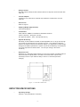
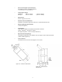
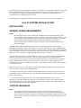
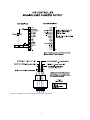
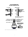
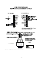
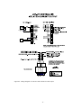
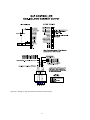
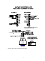
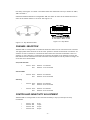
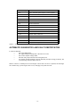
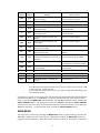
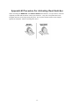
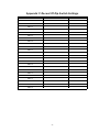
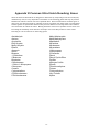
MODEL: U1F, U2F & U4F-UV and UVC120
ULTRAVIOLET FIRE DETECTION SYSTEM
1, 2 and 4 Channel Field Mount Controller
with the UVC120 Detector
Part Num ber: M AN-0016-00 Rev. 2
Copyright © 2002 Net Safety Monitoring Inc.
Printed in Canada
This m anual is provided for inform ational purposes only. Although the inform ation contained in this
m anual is believed to be accurate, it could include technical inaccuracies or typographical errors.
Changes are, therefore, periodically m ade to the inform ation within this docum ent and
incorporated without notice into subsequent revisions of the m anual. Net Safety Monitoring Inc.
assum es no responsibility for any errors that m ay be contained within this m anual.
This m anual is a guide for the use of a 1, 2 and 4 Channel Field Mount Controller and the data
and procedures contained within this docum ent have been verified and are believed to be
adequate for the intended use of the controller. If the controller or procedures are used for
purposes other than as described in the m anual without receiving prior confirm ation of validity or
suitability, Net Safety Monitoring Inc. does not guarantee the results and assum es no obligation or
liability.
No part of this m anual m ay be copied, dissem inated or distributed without the express written
consent of Net Safety Monitoring Inc.
Net Safety Monitoring Inc. products, are carefully designed and m anufactured from high quality
com ponents and can be expected to provide m any years of trouble free service. Each product is
thoroughly tested, inspected and calibrated prior to shipm ent. Failures can occur which are
beyond the control of the m anufacturer. Failures can be m inim ized by adhering to the operating
and m aintenance instructions herein. W here the absolute greatest of reliability is required,
redundancy should be designed into the system .
Net Safety Monitoring Inc., warrants its sensors and detectors against defective parts and
workm anship for a period of 24 m onths from date of purchase and other electronic assem blies for
36 m onths from date of purchase.
No other warranties or liability, expressed or im plied, will be honoured by Net Safety Monitoring
Inc.
Contact Net Safety Monitoring Inc. or an authorized distributor for details.
Table of Contents
Unit I GENERAL INFORMATION . . . . . . . . . . . . . . . . . . . . . . . . . . . . . . . . . . . 1
DESCRIPTION . . . . . . . . . . . . . . . . . . . . . . . . . . . . . . . . . . . . . . . . . . . . . . . . . . . .
FEATURES . . . . . . . . . . . . . . . . . . . . . . . . . . . . . . . . . . . . . . . . . . . . . . . . . . . . . . .
CONTROLLER SPECIFICATIONS . . . . . . . . . . . . . . . . . . . . . . . . . . . . . . . . . . . . .
Figure 1 - Controller Dimensions . . . . . . . . . . . . . . . . . . . . . . . . . . . . . . . .
DETECTOR SPECIFICATIONS . . . . . . . . . . . . . . . . . . . . . . . . . . . . . . . .
Figure 2b - Swivel Mount Dimensions . . . . . . . . . . . . . . . . . . . . . . . . . . . .
Figure 2a - Detector Dimensions . . . . . . . . . . . . . . . . . . . . . . . . . . . . . . . .
BASIC OPERATION - CONTROLLER . . . . . . . . . . . . . . . . . . . . . . . . . . . . . . . . . .
CONTROLLER FACEPLATE DESCRIPTION . . . . . . . . . . . . . . . . . . . . . .
Figure 3 - Controller Face-Plate . . . . . . . . . . . . . . . . . . . . . . . . . . . . . . . . .
OUTPUTS . . . . . . . . . . . . . . . . . . . . . . . . . . . . . . . . . . . . . . . . . . . . . . . . .
Table 1 - Selectable Output Options . . . . . . . . . . . . . . . . . . . . . . . . . . . . .
Figure 4 - Jumper Selection for Isolated or Non-Isolated Current Outputs
PROGRAMMING OPTIONS . . . . . . . . . . . . . . . . . . . . . . . . . . . . . . . . . . .
EXTERNAL RESET . . . . . . . . . . . . . . . . . . . . . . . . . . . . . . . . . . . . . . . . . .
AUTOMATIC DIAGNOSTICS AND FAULT IDENTIFICATION . . . . . . . . .
VOTING LOGIC (not applicable to U1F) . . . . . . . . . . . . . . . . . . . . . . . . . .
DETECTOR . . . . . . . . . . . . . . . . . . . . . . . . . . . . . . . . . . . . . . . . . . . . . . . . . . . . . . .
.
.
.
.
.
.
.
.
.
.
.
.
.
.
.
.
.
.
.
.
.
.
.
.
.
.
.
.
.
.
.
.
.
.
.
.
.
.
.
.
.
.
.
.
.
.
.
.
.
.
.
.
.
.
.
.
.
.
.
.
.
.
.
.
.
.
.
.
.
.
.
.
.
.
.
.
.
.
.
.
.
.
.
.
.
.
.
.
.
.
.
.
.
.
.
.
.
.
.
.
.
.
.
.
.
.
.
.
.
.
.
.
.
.
.
.
.
.
.
.
.
.
.
.
.
.
.
.
.
.
.
.
.
.
.
.
.
.
.
.
.
.
.
.
.
.
.
.
.
.
.
.
.
.
.
.
.
.
.
.
.
.
.
.
.
.
.
.
.
.
.
.
.
.
.
.
.
.
.
.
.
.
.
.
.
.
.
.
.
.
.
.
.
.
.
.
.
.
1
1
1
2
2
3
3
4
4
4
5
5
5
6
6
6
7
7
Unit II UV FIRE DETECTION . . . . . . . . . . . . . . . . . . . . . . . . . . . . . . . . . . . . . . 7
SYSTEM APPLICATION . . . . . . . . . . . . . . . . . . .
DETECTOR SENSITIVITY . . . . . . . . . . . . . . . . .
SPECTRAL SENSITIVITY RANGE . . . .
Figure 5 - Various Spectral Distributions
CONE OF . . . . . . . . . . . . . . . . . . . . . . .
VISION . . . . . . . . . . . . . . . . . . . . . . . . . .
Figure 6 - Detector Cone of Vision . . . . .
SYSTEM SENSITIVITY . . . . . . . . . . . . . . . . . . . .
.
.
.
.
.
.
.
.
.
.
.
.
.
.
.
.
.
.
.
.
.
.
.
.
.
.
.
.
.
.
.
.
.
.
.
.
.
.
.
.
.
.
.
.
.
.
.
.
.
.
.
.
.
.
.
.
.
.
.
.
.
.
.
.
.
.
.
.
.
.
.
.
.
.
.
.
.
.
.
.
.
.
.
.
.
.
.
.
.
.
.
.
.
.
.
.
.
.
.
.
.
.
.
.
.
.
.
.
.
.
.
.
.
.
.
.
.
.
.
.
.
.
.
.
.
.
.
.
.
.
.
.
.
.
.
.
.
.
.
.
.
.
.
.
.
.
.
.
.
.
.
.
.
.
.
.
.
.
.
.
.
.
.
.
.
.
.
.
.
.
.
.
.
.
.
.
.
.
.
.
.
.
.
.
.
.
.
.
.
.
.
.
.
.
.
.
.
.
.
.
.
.
.
.
.
.
.
.
.
.
.
.
.
.
.
.
.
.
.
.
.
.
.
.
.
.
.
.
.
.
.
.
.
.
.
.
.
.
.
.
.
.
.
.
.
.
.
.
.
.
.
.
.
.
.
.
.
.
.
.
.
.
.
.
.
.
.
.
.
.
.
.
.
.
.
.
.
.
.
.
.
.
.
.
.
.
.
.
.
.
.
.
.
.
.
.
7
8
8
8
9
9
9
9
Unit III SYSTEM INSTALLATION . . . . . . . . . . . . . . . . . . . . . . . . . . . . . . . . . . 10
INSTALLATION . . . . . . . . . . . . . . . . . . . . . . . . . . . . . . . . . . . . . . . . . . . . . . . .
GENERAL W IRING REQUIREMENTS . . . . . . . . . . . . . . . . . . . . . . .
CONTROLLER W IRING . . . . . . . . . . . . . . . . . . . . . . . . . . . . . . . . . .
Figure 7a - W iring for U1F-UV with Non-Isolated Current Output . . .
Figure 7b - W iring for U1F-UV with Isolated Current Output . . . . . . .
Figure 8a - W iring for U2F-UV with Non-Isolated Output . . . . . . . . . .
Figure 8b - W iring Diagram for U2F-UV with Isolated Current Output
Figure 9a - W iring for U4F-UV with Non-Isolated Current Output . . .
Figure 9b - W iring for U4F-UV with Isolated Current Output . . . . . . .
POSITION AND DENSITY OF DETECTORS . . . . . . . . . . . . . . . . . . . . . . . . .
MOUNTING THE DETECTOR . . . . . . . . . . . . . . . . . . . . . . . . . . . . .
Figure 10 - Detector with Swivel Mount Assembly . . . . . . . . . . . . . .
DIP SW ITCH SETTINGS . . . . . . . . . . . . . . . . . . . . . . . . . . . . . . . . . . . . . . . .
Figure 11b - Dip Switch . . . . . . . . . . . . . . . . . . . . . . . . . . . . . . . . . . .
Figure 11a - Dip Switch Position . . . . . . . . . . . . . . . . . . . . . . . . . . . .
CHANNEL SELECTION . . . . . . . . . . . . . . . . . . . . . . . . . . . . . . . . . . .
CONTROLLER SENSITIVITY ADJUSTMENT . . . . . . . . . . . . . . . . .
FIRE AREA VOTING SEQUENCE (not applicable to U1F) . . . . . . . .
RELAY OUTPUTS LATCHING/NON-LATCHING . . . . . . . . . . . . . . .
RELAY OUTPUTS ENERGIZED/DE-ENERGIZED . . . . . . . . . . . . . .
TIME DELAY FOR AREA ALARMS . . . . . . . . . . . . . . . . . . . . . . . . . .
RELAY SETTINGS . . . . . . . . . . . . . . . . . . . . . . . . . . . . . . . . . . . . . . . . . . . . .
Figure 11c - Relay Position . . . . . . . . . . . . . . . . . . . . . . . . . . . . . . . .
Figure 11d - Relay Settings . . . . . . . . . . . . . . . . . . . . . . . . . . . . . . . .
.
.
.
.
.
.
.
.
.
.
.
.
.
.
.
.
.
.
.
.
.
.
.
.
.
.
.
.
.
.
.
.
.
.
.
.
.
.
.
.
.
.
.
.
.
.
.
.
.
.
.
.
.
.
.
.
.
.
.
.
.
.
.
.
.
.
.
.
.
.
.
.
.
.
.
.
.
.
.
.
.
.
.
.
.
.
.
.
.
.
.
.
.
.
.
.
.
.
.
.
.
.
.
.
.
.
.
.
.
.
.
.
.
.
.
.
.
.
.
.
.
.
.
.
.
.
.
.
.
.
.
.
.
.
.
.
.
.
.
.
.
.
.
.
.
.
.
.
.
.
.
.
.
.
.
.
.
.
.
.
.
.
.
.
.
.
.
.
.
.
.
.
.
.
.
.
.
.
.
.
.
.
.
.
.
.
.
.
.
.
.
.
.
.
.
.
.
.
.
.
.
.
.
.
.
.
.
.
.
.
.
.
.
.
.
.
.
.
.
.
.
.
.
.
.
.
.
.
.
.
.
.
.
.
.
.
.
.
.
.
.
.
.
.
.
.
.
.
.
.
.
.
.
.
.
.
.
.
.
.
.
.
.
.
.
.
.
.
.
.
.
.
.
.
.
.
.
.
.
.
.
.
.
.
.
.
.
.
.
.
.
.
.
.
.
.
.
.
.
.
.
.
.
.
.
.
.
.
.
.
.
.
.
.
.
.
.
.
.
.
.
.
.
.
.
.
.
.
.
.
.
.
.
.
.
.
10
10
10
12
13
14
15
16
17
18
18
18
18
19
19
19
19
20
20
20
21
21
21
21
Unit IV SYSTEM OPERATION . . . . . . . . . . . . . . . . . . . . . . . . . . . . . . . . . . . . 22
STARTUP PROCEDURE . . . . . . . . . . . . . . . . . . . . . . . . . . . .
CHECKOUT PROCEDURE . . . . . . . . . . . . . . . . . . . . . . . . . .
MANUAL vi CHECK/COUNT TEST . . . . . . . . . . . . . . . . . . . .
MANUAL CHECK PROCEDURE . . . . . . . . . . . . . . . . . . . . . .
ALTERNATE TEST PROCEDURE . . . . . . . . . . . . . . . . . . . . .
NORMAL OPERATION . . . . . . . . . . . . . . . . . . . . . . . . . . . . . . . . . . . .
FIRE RESPONSE . . . . . . . . . . . . . . . . . . . . . . . . . . . . . . . . . .
Table 2 - Current Outputs . . . . . . . . . . . . . . . . . . . . . . . . . . . .
AUTOMATIC DIAGNOSTICS AND FAULT IDENTIFICATION
Table 3 - Error Codes . . . . . . . . . . . . . . . . . . . . . . . . . . . . . . .
MAIN MENU . . . . . . . . . . . . . . . . . . . . . . . . . . . . . . . . . . . . . . . . . . . . .
BYPASS MODE (bPS) . . . . . . . . . . . . . . . . . . . . . . . . . . . . . .
SPECIAL FUNCTION MENU . . . . . . . . . . . . . . . . . . . . . . . . . . . . . . . .
FORCED CURRENT OUTPUT MODE (FoP) . . . . . . . . . . . . .
CURRENT CALIBRATION MODE (CuC) . . . . . . . . . . . . . . . .
ADDRESS SET MODE (Adr Set) (Do not use) . . . . . . . . . . . .
.
.
.
.
.
.
.
.
.
.
.
.
.
.
.
.
.
.
.
.
.
.
.
.
.
.
.
.
.
.
.
.
.
.
.
.
.
.
.
.
.
.
.
.
.
.
.
.
.
.
.
.
.
.
.
.
.
.
.
.
.
.
.
.
.
.
.
.
.
.
.
.
.
.
.
.
.
.
.
.
.
.
.
.
.
.
.
.
.
.
.
.
.
.
.
.
.
.
.
.
.
.
.
.
.
.
.
.
.
.
.
.
.
.
.
.
.
.
.
.
.
.
.
.
.
.
.
.
.
.
.
.
.
.
.
.
.
.
.
.
.
.
.
.
.
.
.
.
.
.
.
.
.
.
.
.
.
.
.
.
.
.
.
.
.
.
.
.
.
.
.
.
.
.
.
.
.
.
.
.
.
.
.
.
.
.
.
.
.
.
.
.
.
.
.
.
.
.
.
.
.
.
.
.
.
.
.
.
.
.
.
.
.
.
.
.
.
.
.
.
.
.
.
.
.
.
.
.
.
.
.
.
.
.
.
.
.
.
.
.
.
.
.
.
.
.
.
.
.
.
.
.
.
.
.
.
.
.
.
.
.
.
.
.
.
.
.
.
.
.
.
.
.
.
.
.
.
.
.
.
.
.
.
.
.
.
.
.
.
.
.
.
.
.
.
.
.
.
.
.
.
.
.
.
.
.
.
.
.
.
.
.
.
.
.
.
.
.
.
22
22
22
23
24
24
24
25
25
26
26
27
27
27
28
28
Unit V MAINTENANCE . . . . . . . . . . . . . . . . . . . . . . . . . . . . . . . . . . . . . . . . . . 29
ROUTINE MAINTENANCE . . . . . . . . . . . . . . . . . . . . . . . . . . . . . . . . . . . . . . . . . . . . . . . . . . . . . 29
TROUBLESHOOTING . . . . . . . . . . . . . . . . . . . . . . . . . . . . . . . . . . . . . . . . . . . . . . . . . . . . . . . . . 29
DEVICE REPAIR AND RETURN . . . . . . . . . . . . . . . . . . . . . . . . . . . . . . . . . . . . . . . . . . . . . . . . . 29
Appendix A Net Safety Monitoring Inc. Electrostatic Sensitive Device
Handling Procedure . . . . . . . . . . . . . . . . . . . . . . . . . . . . . . . . . . . . . . . . . . . . 32
Appendix B Procedure For Activating Reed Switches . . . . . . . . . . . . . . . . 33
Appendix C Record Of Dip Switch Settings . . . . . . . . . . . . . . . . . . . . . . . . . 34
Appendix D Common Ultra-Violet Absorbing Gases . . . . . . . . . . . . . . . . . . 35
Appendix E Wire Resistance In Ohms . . . . . . . . . . . . . . . . . . . . . . . . . . . . . 36
Unit I GENERAL INFORMATION
DESCRIPTION
The UVC120 Flam e Detectors com bined with the U1F, U2F or U4F-UV Fire Controller provide
fast, reliable flam e detection in a wide variety of applications. The m icroprocessor based
controllers sim ultaneously m onitor up to four ultraviolet (UV) detectors to provide m axim um
operating flexibility at m inim um expense. The Autom atic Visual Integrity (vi) feature provides a
continuous check of optical surfaces, sensitivity and electronic circuitry of the detector/controller
system . Autom atic fault identification m onitors system operation and provides a digital display of
system status using a num erical code. Controller response includes actuation of relays for direct
control of field response devices and a full array of faceplate indicators. Other features include
individual channel and area identification, "voting" capability and m anual vi testing.
FEATURES
<
<
<
<
<
<
<
<
<
<
<
<
<
<
<
Non-Intrusive testing activated by m agnets
Instantaneous response to ultraviolet radiation
Autom atic and m anual Visual Integrity (vi) testing
Adjustable sensitivity and tim e delay
All autom atic test functions perform ed with the system on line
Autom atic fault identification
Individual channel identification with voting options
Latching Area LEDs identify the area responding to fire
Microprocessor-based controller is easily field-program m able.
Two digital displays, one bar graph display and high intensity LEDs indicate
system status inform ation
Relay outputs are field adjustable as latching or non-latching
Alarm relays are program m able for norm ally energized or de-energized operation
Individual detector output (count rate) can be visually m onitored on the digital
display
Two 4-20m A current outputs (U2F and U4F). One 4-20m A output on U1F
Conduit seals recom m ended to prevent m oisture dam age but not required
CONTROLLER SPECIFICATIONS
<
Operating Voltage:
24 Volts DC nom inal. 18 to 32Vdc.
<
Pow er Consumption (controller only):
2.4 watts nom inal, 4.4 watts m axim um .
100 m A nom inal, 180 m A m axim um at 24 Volts DC.
Maxim um startup current is 1.5 Am peres for 10 m illiseconds. Power supplies
with fold back current lim iting are not recom m ended.
<
M aximum Ripple:
Ripple should not exceed 5 Volts peak-to-peak. The sum of DC plus ripple m ust
be $18 Vdc and #32 Vdc
<
Temperature Range:
Operating:
-40ºC to +85ºC
Storage:
-55ºC to +150ºC
-1-
(-40ºF to +185ºF)
(-65ºF to +302ºF)
<
Relay Contacts:
Norm ally open/norm ally closed contacts rated for 5 Am peres at 30 Volts DC/ 250
Volts AC
<
Current Outputs:
4-20m A DC into a m axim um external loop resistance of 600 Ohm s at 18-32
Volts DC
<
Dimensions:
Refer to Figure 1
<
Shipping W eight (approximate):
2 lbs (0.9 kilogram s)
<
Certification:
CSA, NRTL/C, NEMA 4X certified for hazardous locations
Class 1, Division 1, Groups B, C and D
IEC approval (Class 1, Zone 1 Groups IIB+H2 T5)
<
System Sensitivity:
Sensitivity for the standard controller is field adjustable over a range of 8 through
120 counts per second (cps) in increm ents of 8 cps. The m axim um response
distance is achieved at an 8 cps sensitivity setting. For applications involving high
background radiation potential, the system can be de-sensitized by increasing the
count rate required to actuate alarm s. The 120 cps setting is the lowest
sensitivity.
<
Response Time:
Response to a saturating (high intensity) UV source is typically 10 m illiseconds for
the instant alarm outputs and 0.5 seconds for the area alarm outputs when
sensitivity is set for 8 cps and tim e delay is set for 0.5 seconds (m inim um
settings).
Figure 1 - Controller Dimensions
DETECTOR SPECIFICATIONS
<
Operating Voltage:
290Vdc ± 3Vdc (provided for controller)
-2-
<
Pow er Consumption (each detector):
0.29 W atts nom inal, 0.5 W atts m axim um
1 m A nom inal, 1.7 m A m axim um
<
Temperature Range:
Operating:
-40ºC to +125ºC
Storage:
-55ºC to +150ºC
(-40ºF to +257ºF)
(-65ºF to +302ºF)
<
Dimensions:
Refer to Figures 2a and 2b
<
Detector Enclosure M aterials:
Available in anodized copper-free alum inum or optional stainless steel
<
Shipping W eight (approximate):
2 lbs (0.9 kilogram s)
<
Certification:
CSA, NRTL/C, NEMA 4X certified for hazardous locations
Class 1, Division 1, Groups B, C and D
IEC approval (Class 1, Zone 1 Groups IIB+H2 T5)
<
Spectral Sensitivity Range:
The detector responds to UV radiation over the range of 185 to 260 nanom etres
(1850 to 2600 angstrom s)
<
Cone of Vision:
The Detector has a nom inal 120 degree cone of vision
Figure 2a - Detector Dimensions
Figure 2b - Swivel Mount
Dim ensions
-3-
BASIC OPERATION - CONTROLLER
CONTROLLER FACEPLATE DESCRIPTION
The controller faceplate provides LEDs and two digital displays for identifying status conditions, a
bar graph display for indicating an alarm condition and MENU/SET and SELECT/RESET pushbutton switches (See appendix for instructions on activation) for testing and resetting the system.
Refer to Figure 3.
Figure 3 - Controller Face-Plate
<
Digital Displays - The left side of the digital display is normally off. If a fire alarm
or visual integrity fault is detected, it indicates the channel number of the alarm or
fault. The digital displays indicate system status including system error codes,
visual integrity (vi) faults, system faults or fire alarms. The right side of the
display shows ‘nor’ in normal operating mode. If more than one channel is in an
alarm or fault condition the digital displays will cycle through these channels.
Since at least one side of the display is always lit they also function as a power
indicator.
<
Bar Graph Display - Normally off. Flashing when fire detected in any area.
<
Instant LED - (no time delay) Flashes when any detector signal exceeds the fire
sensitivity setting.
<
Area 1 & 2 LEDs - (Area 1 only for U1F) If the selected “voting” criteria of the
area and the preset time delay has elapsed the corresponding LED starts
flashing.
<
Fault LED - flashes upon detection of an overall system fault or vi fault.
<
Channel LEDs - (1, 2 or 4 depending on model) flash to indicate detector in
alarm and remain illuminated until reset after an alarm condition has returned to
normal.
<
MENU/SET Reed Switch - is used to enter the main menu, to toggle through
menu selections and in conjunction with the SELECT/RESET Reed Switch to
enter the special functions menu.
<
SELECT/RESET Reed Switch - is used for a basic system reset, menu selection
and with the MENU/SET Reed Switch to enter the special functions menu. This
switch is also used during the manual vi test.
-4-
OUTPUTS
Relay Outputs:
The Instant, Area and Fault relays have SPDT contacts rated 5 Amps at 30 Volts DC or 250 Volts
AC.
The Instant and Area alarm relays are programmable for either normally energized or normally
de-energized operation and for latching or non-latching (programmable as a group not
individually). The fault relay is only normally energized. The relays can be configured with jumpers
for normally open or normally closed contacts.
RECOMMENDATION
The fault relay output should not be used to activate an automatic shutdown procedure.
The fault output indicates a potential problem with the controller, not an alarm condition.
Refer to Table 1 for a summary of the relay programming options.
OUTPUT
Selectable Normally
Open/Closed
Selectable Normally
Energized/De-Energized
Selectable
Latching/Non-Latching
AREA 1
Y
Y
Y
INSTANT
Y
Y
Y
FAULT
Y
N2
N3
Table 1 - Selectable Output Options
1
2
3
Area alarms are programmed together, not individually.
Fault relay is normally energized.
Fault relay is non-latching.
Current Outputs:
4-20 mA DC current outputs transmit system information to other devices. The current outputs
can be wired for isolated or non-isolated operation by changing the jumpers as shown in Figure 4.
Refer to Unit IV, System Operation for a description of the current output signal levels.
-5-
Figure 4 - Jumper Selection for Isolated or Non-Isolated Current Outputs
PROGRAMMING OPTIONS
DIP switches located on the circuit board are used to “program” various options including:
<
channel selection,
<
system sensitivity,
<
fire area voting logic,
<
time delay for fire area alarms,
<
relay latching/non-latching selection, and
<
relay energized/de-energized selection.
NOTE
Power to the controller must be cycled to make dip switch changes take effect.
EXTERNAL RESET
A normally open, momentary closure switch connected between the external reset terminal and
the negative power terminal provides remote reset.
AUTOMATIC DIAGNOSTICS AND FAULT IDENTIFICATION
The microprocessor-based controller features self-testing circuitry that continuously checks for
problems that could prevent proper system response. W hen power is applied, the microprocessor
automatically tests memory. In the Normal Operating Mode it continuously monitors the system to
ensure proper functioning. A "watchdog" timer is maintained to ensure that the program is running
correctly.
The main loop of the operating program continuously cycles through the Automatic Visual Integrity
test, checking each detector and its wiring. The microprocessor can be interrupted by
-6-
(Automatic Diagnostics and Fault Identification Cont)
any one of several status changes such as a fault or a "fire" signal from one of the detection areas
to take appropriate action.
If a system or vi fault is detected the Fault LED flashes, digital displays and current outputs
identify the nature of the fault and the fault relay is de-energized.
VOTING LOGIC (not applicable to U1F)
The controller can be DIP switch configured for either one or two monitoring areas. For a one
area configuration, all channels are considered as being in Area 1 and both Area alarm relays will
be activated together.
The dip switches can be set so that only one channel need be in alarm to activate the area alarm
or any two channels must ‘vote’ (see a fire at the same time) to activate the area alarm. The
instant alarm will be activated when any channel sees UV radiation exceeding the preset
sensitivity setting, no matter what voting option is being used.
For a two area configuration, channel one (one and two for U4F) make up Area 1 and channel
three (three and four for U4F) make up Area 2. W ith the U4F each Area alarm may be
programmed with different voting criteria (ie. Area 1 may be set so that either channel one OR
channel two may activate the area alarm, and Area 2 may be set so that both channels three AND
four must see the fire at the same time to activate the Area alarm).
DETECTOR
The detector responds to UV radiation over the range of 185 to 260 nanometers. It is not
sensitive to direct or reflected sunlight nor to normal artificial lighting.
The detector is housed in an explosion-proof enclosure that is designed to meet most national and
international standards. It is available in anodized aluminum or optional stainless steel.
The detector is typically mounted with a swivel mounting assembly which is recommended. Other
mounting arrangements are possible.
Unit II UV FIRE DETECTION
SYSTEM APPLICATION
The detector responds instantly to ultraviolet radiation emitted by a flame. It is designed for use in
hazardous locations and is suitable for use in outdoor applications.
Typical applications for UV detection systems are:
<
<
<
<
around highly combustible materials
if instantaneous response to flame is needed
where automated fire protection is required
to protect large capital investments
Petroleum Products Handling
<
petroleum loading terminals
<
offshore platforms
<
pipeline stations
<
tank farms
-7-
<
<
refineries
engine rooms
Gaseous Fuel Handling
<
butane and propane loading and storage
<
pipeline compressor stations
<
gas gathering facilities
<
LNG loading, transfer and storage
<
hydrogen
<
gas turbines
Other Processes
<
paint spray booths
<
chemical and petrochemical production
<
powder coating booths
Automated fire protection systems also have applications in any manufacturing or research
facility where the potential of fire may be low to moderate but the losses due to a fire would be
high.
DETECTOR SENSITIVITY
SPECTRAL SENSITIVITY RANGE
The UV fire detector responds to radiation wavelengths of 185 to 260 nanometres (1850 to 2600
angstroms). Figure 5 illustrates the range of sensitivity and compares this range to other forms of
radiation. Note that UV radiation reaching the earth from the sun does not extend into the
sensitivity range of the detector. Nor does radiation from normal artificial lighting, such as
fluorescent, mercury vapor and incandescent lamps.
Figure 5 - Various Spectral Distributions
NOTE
Some mercury vapor lamps can operate for extended periods with cracked or damaged
envelopes and will then emit UV radiation in the range of the detector. Remove defective
mercury vapor lamps from service.
-8-
The UV sensor responds to radiation other than ultraviolet. X-rays can activate the detector and
are often used in industrial inspection. It may be necessary to disable the system if X-ray
inspection is conducted nearby.
UV radiation other than that produced by an actual fire is referred to as “background UV.” An
example of a high level of background UV could be the case of a flare stack situated outside of a
building. The UV radiation produced by this flare may be detected when a door to the building is
opened. W indows or reflective surfaces may also result in unusually high levels of UV radiation
entering the building from the flare. In a situation like this, the fire detection system response must
be carefully checked and the sensitivity level adjusted high enough so that this “background” UV
will not cause false alarms.
Caution must be exercised if the detection system is turned off, since the hazardous area will
not be protected.
NOTE
Ultraviolet detectors are sensitive to arc welding and if this type of radiation can be
expected, nuisance alarms must be controlled through proper application including careful
positioning and shielding of the detectors. Some applications may require a UV/IR
system.
CONE OF VISION
The fire detector has a nominal 120 degree cone of vision. Figure 6 shows the cone of vision and
detector response to a UV source at various distances. The practical application distance is up to
about 50 feet (15 meters). The distance is directly related to the intensity of the ultraviolet
radiation source. Programming the controller to require a high count rate results in low system
sensitivity. Consider that UV absorbing chemical vapors may be present. (See Appendix D)
Figure 6 - Detector Cone of Vision
SYSTEM SENSITIVITY
The UV tube count rate generated by different fires at the same distance is unpredictable.
Generally, if a fire doubles in size the tube response is increased by about 60 percent.
Controller sensitivity and time delay settings for various applications is dependent on the severity
of the hazard and the action required if a fire occurs. The system can be adjusted to various
-9-
sensitivity levels by programming the controller to respond at a pre-determined detector count rate
which is dependent upon the intensity of the ultraviolet radiation reaching the detector, which in
turn depends on the type of fuel, temperature, flame size, distance from the detector and
concentration of UV absorbing vapors present.
Programming the controller to respond to a low count rate results in high system sensitivity.
Unit III SYSTEM INSTALLATION
INSTALLATION
GENERAL WIRING REQUIREMENTS
NOTE
The wiring procedures in this manual are intended to ensure proper functioning of the
device under normal conditions. However, because of the many variations in wiring codes
and regulations, total compliance to these ordinances cannot be guaranteed. Be certain
that all wiring complies with applicable regulations that relate to the installation of
electrical equipment in a hazardous area. If in doubt, consult a qualified official before
wiring the system.
Shielded cable is highly recommended for power input and signal wires to protect against
interference caused by extraneous electrical 'noise'. Relay outputs do not require shielded cable.
Recommended detector cable is four conductor, shielded cable, 18 AW G, rated 300V. If the wiring
cable is installed in conduit, the conduit must not be used for wiring to other electrical equipment.
Detectors can be located up to 2000 feet (600 metres) from the controller.
W ater will damage electronic devices. Moisture in the air can condense within electrical conduit
and drain into the enclosure, therefore, water-proof and explosion-proof conduit seals are
recommended to prevent water accumulation within the enclosure. Seals should be located as
close to the device as possible and not more than 18 inches (46 cm) away. Explosion-proof
installations may require an additional seal where conduit enters a non-hazardous area. Conform
to local wiring codes.
W hen pouring a seal, use a fibre dam to assure proper formation of the seal. The seals should
never be poured at temperatures below freezing.
The jacket and shielding of the cable should be stripped back to permit the seal to form around
the individual wires. This will prevent air, gas and water leakage through the inside of the shield
and into the enclosure.
It is recommended that explosion-proof drains and conduit breathers be used. In some
applications, alternate changes in temperature and barometric pressure can cause 'breathing'
which allows moist air to enter and circulate inside the conduit. Joints in the conduit system are
seldom tight enough to prevent this 'breathing'.
CONTROLLER WIRING
NOTE
The controller contains semiconductor devices that are susceptible to damage by
electrostatic discharge. An electrostatic charge can build up on the skin and discharge
when an object is touched. Therefore, use caution when handling, taking care not to touch
the terminals or electronic components. For more information on proper handling, refer to
the Appendix.
- 10 -
The controller can be configured for isolated or non-isolated current outputs by changing jumpers
on circuit board as per Figure 4. Figures 7a, 8a and 9a show the wiring for isolated current
outputs and Figures 7b, 8b and 9b show wiring for non-isolated current outputs.
- 11 -
Figure 7a - W iring for U1F-UV with Non-Isolated Current Output
- 12 -
Figure 7b - W iring for U1F-UV with Isolated Current Output
- 13 -
Figure 8a - W iring for U2F-UV with Non-Isolated Output
- 14 -
Figure 8b - W iring Diagram for U2F-UV with Isolated Current Output
- 15 -
Figure 9a - W iring for U4F-UV with Non-Isolated Current Output
- 16 -
Figure 9b - W iring for U4F-UV with Isolated Current Output
- 17 -
POSITION AND DENSITY OF DETECTORS
The detector has a nominal 120º cone of vision. In an application such as a loading rack with a
ceiling height of 25 feet (7.5 meters) where it is desired to have complete detector coverage at
floor level and a detector is mounted 2 feet (0.6 meter) from the ceiling and pointed straight down,
the distance from the detector to the designated level would be 23 feet (7 meters) and because of
its 120º cone of vision the detector would cover a circular area 80 feet (24 meters) in diameter at
floor level. A sketch of the area to be covered will indicate the number of detectors required to
monitor the area. Detectors should be placed as close as practical to the expected fire hazard.
NOTE
Do not mount UV detectors close to the ceiling of enclosed buildings if smoke might
accumulate before the break-out of flame. It is preferable to mount the detectors on walls
a few feet (or about 1 meter) below the ceiling where they may respond before being
obscured by smoke. Consider shortening time delay settings when smoke is expected to
accumulate during a fire. If dense smoke is likely to accumulate prior to flame (as in an
electrical fire), supplement UV detectors with other protection.
MOUNTING THE DETECTOR
Locate detectors to ensure an unobstructed view of the area to be monitored and where
accessible for cleaning the detector window and vi reflecting surface. Take care so dirt will not
accumulate and obscure the detector viewing window. Detectors mounted outdoors should be
pointed downward to prevent the cone of vision from scanning the horizon where long duration
lightning flashes or far-off arc welding may activate the detector. To minimize dirt accumulation
around the vi surfaces, mount the detectors so that the internal vi tube is on top. The silver
external reflector should be placed directly over the vi tube. Refer to Figures 2a and 2b for the
detector and swivel mounting assembly dimensions. Refer to Figure 10 for a diagram of the
assembled detector and swivel assembly.
Figure 10 - Detector with Swivel Mount Assembly
DIP SWITCH SETTINGS
NOTE
To make DIP switch changes take effect, cycle controller power off then on.
The DIP switches on the controller circuit board must be properly programmed before applying
power to the system. There are three banks of 8 position DIP switches which are OFF or ON to
select area and detector combinations, controller sensitivity, fire voting logic, output latching and
- 18 -
time delay. See Figure 11a below. The switch banks are numbered from top to bottom as SW 5,
SW 4 and SW 3.
Individual ON/OFF switches are designated “SW X.Y where ‘X’ refers to the switch bank and ‘Y’
refers to the switch number on ‘X’ bank. See Figure 11b.
.
Figure 11b - Dip Switch
Figure 11a - Dip Switch Position
CHANNEL SELECTION
Switches SW 3.1 through SW 3.4 enable the detectors that are to be connected to the controller.
The appropriate switch must be set to the ‘OFF’ position to enable each detector connected. If a
switch is off but no detector is connected in that location the controller will indicate a fault. If a
switch is on, but a detector is connected, the controller will appear to be operating correctly but
that detector will be eliminated from the Automatic vi test sequence and any faults occurring in its
circuit will not be annunciated.
U1F, U2F and U4F
<
SW 3.1: OFF:
ON:
detector 1 connected
detector 1 not connected
SW 3.2: OFF:
ON:
detector 2 connected
detector 2 not connected
<
SW 3.3: OFF:
ON:
detector 3 connected
detector 3 not connected
<
SW 3.4: OFF:
ON:
detector 4 connected
detector 4 not connected
U2F and U4F
<
U4F only
CONTROLLER SENSITIVITY ADJUSTMENT
Switches SW 4.1 through SW 4.4 set controller sensitivity in 8 cps (counts per second)
increments.
<
<
<
<
SW
SW
SW
SW
4.1
4.2
4.3
4.4
ON:
ON:
ON:
ON:
8 cps
16 cps
32 cps
64 cps
- 19 -
The switch values are added together. These switches are factory set to a sensitivity of 24 counts
per second, as shown in the example.
Example:
SW
SW
SW
SW
4.1
4.2
4.3
4.4
ON
ON
OFF
OFF
sensitivity
= 24 cps
FIRE AREA VOTING SEQUENCE (not applicable to U1F)
SW 4.5, SW 4.6 and SW 4.8 select voting sequence which can be Fire Area 1 only (all detectors
in one area) or Fire Area 1 separate from Fire Area 2. W hen separate, Fire Area 1 consists of
detector 1 (1 and 2 for U4F) and Fire Area 2 consists of detector 2 (detector 3 and 4 for U4F).
Switch SW 4.7 should be placed in the ‘OFF’ position at all times.
Fire Area 1 Separate from Fire Area 2:
<
<
<
<
SW 4.7 OFF
SW 4.8 ON
SW 4.5 programs Fire Area 1 (detector 1 for U2F) (detectors 1 and 2
for U4F)
OFF: votes one of two detectors (always OFF for U2F)
ON:
votes two of two detectors
SW 4.6 programs Fire Area 2 (detector 3 for U2F) (detectors 3 and 4
for U4F)
OFF: votes one of two detectors (always OFF for U2F)
ON:
votes two of two detectors
Fire Area 1 only:
<
<
<
<
SW
SW
SW
SW
4.8
4.7
4.6
4.5
OFF
OFF
OFF
OFF:
ON:
votes any one of all detectors
votes any two of all detectors
RELAY OUTPUTS LATCHING/NON-LATCHING
The alarm relays are programmed together for latching or non-latching operation (the fault relay is
only non-latching).
<
5.1: ON:
OFF:
non-latching operation
latching operation
NOTE
Latched outputs are unlatched by activating the RESET switch.
RELAY OUTPUTS ENERGIZED/DE-ENERGIZED
The area and instant alarm relays can be programmed for normally energized or normally deenergized operation using SW 5.2 . The fault relay is always normally energized. SW 5.2 is factory
set to de-energized operation (ON)
- 20 -
<
SW 5.2: OFF:
ON:
normally energized operation
normally de-energized operation
- 21 -
TIME DELAY FOR AREA ALARMS
NOTE
Time delay affects the Area alarms only; the instant alarm operates as soon as a flame is
detected.
The time delay for the Area alarms is set using SW 5.3 to SW 5.7. If all of the switches are placed
in the ‘OFF’ position the time delay will be 0.5 seconds (minimum setting).
<
<
<
<
<
<
SW
SW
SW
SW
SW
SW
5.3-7:
5.3: ON:
5.4: ON:
5.5: ON:
5.6: ON:
5.7: ON:
OFF: 0.5 sec. time delay
0.5 sec. time delay
1 sec. time delay
2 sec. time delay
4 sec. time delay
8 sec. time delay
If switch 5.8 is "OFF" then in Bypass m ode:
- the current output is 4 m A
- the Fault Relay state rem ains unchanged (if it was energized, it rem ains energized; if it
was de-energized, it rem ains de-energized)
If switch 5.8 is "ON" then in Bypass m ode:
- the current output is 3 m A
- the Fault Relay is de-energized
The total time delay is the added value of the switches turned ON. Switches can be turned ON in
any combination for a time delay from 0.5 to 15.5 seconds in half second increments. These
switches are factory set to a 3.0 second time delay as shown in the example below.
Example:
SW
SW
SW
SW
SW
5.3
5.4
5.5
5.6
5.7
OFF
ON
ON
OFF
OFF
time delay
= 2.5 sec.
NOTE
SW 3.5 through SW 3.8 are not used.
RELAY SETTINGS
There are four relays on the controller circuit board that can be configured for normally OFF or
normally ON operation by moving the jumpers which are located below the relays. See
Figure 11c for the location of the relays on the circuit board and Figure 11d for the settings.
- 22 -
Figure 11c - Relay Position
Figure 11d - Relay Settings
Unit IV SYSTEM OPERATION
STARTUP PROCEDURE
CAUTION
Placing the controller in the Bypass mode inhibits its outputs, preventing actuation of any
extinguishing or alarm circuits that are connected. For maximum safety, however, secure
output loads (remove power from any devices that would normally be actuated by the
system) before manually testing the system. Remember to place this same equipment
back into service when the test is complete.
1.
After setting the DIP switches and making all electrical connections, apply power
to the controller.
2.
Perform the Checkout Procedure.
3.
If the controller appears to be operating normally (performs power-up countdown
and then shows ‘Nor’ on the display), remove mechanical blocking devices and
restore power to the extinguishing loads.
NOTE
Be sure that the detector is correctly aimed at the potential hazard and that no
obstructions interfere with its line of vision. UV absorbing gases should not exist between
the detector and the potential hazard.
CHECKOUT PROCEDURE
CAUTION
W hen testing the system, be sure to secure all output devices to prevent unwanted
activation of this equipment and remember to place these same devices back into service
when the check-out is complete.
MANUAL vi CHECK/COUNT TEST
The Autom atic vi (visual integrity) feature checks the detectors for correct response.
- 23 -
The visual integrity test and the count test are performed at the same time.
1.
Place the controller in the bypass mode (all outputs inhibited) by keeping the
MENU/SET switch activated until ‘Chc’ ‘Err’ or ‘bPS’ are shown on the digital
displays. Release the switch and activate it again until ‘bPS’ is shown on the right
side of the display, then activate the SELECT/RESET switch. The right digital
display will show ‘Chn’ and the left side of the digital display will show ‘bPS’.
2.
Activate the MENU/SET switch again to toggle through the available channels.
W hen the desired channel is shown on the left side of the display, activate the
SELECT/RESET switch.
3.
W hile in the bypass mode, the right side of the display will show the counts per
second produced by the background UV in the detector’s range of vision.
Activating the SELECT/RESET switch will perform the manual vi test, a
significant increase in the count displayed should be observed. (Counts should be
greater than 150 and less than 400. If the counts read are not with in this range
the lens and reflector need cleaning or the vi adjustment allen screw the sensor
on module needs to be repositioned (only available on tube modules with
aluminum shroud.)
4.
To exit the bypass mode, activate the MENU/SET switch repeatedly until ‘test’ is
shown on the left side of the display. Now activate the SELECT/RESET switch.
NOTE
The Automatic vi system continuously monitors the operation of the detector but does not
monitor external relays or equipment that may be operated from the relay outputs. It is
important that the system be manually checked using the MANUAL check procedure on a
regular basis. The whole system (including external equipment) should be checked
periodically using a UV Test Lamp to simulate a fire.
MANUAL CHECK PROCEDURE
The whole system should be checked periodically with a UV test lamp to make sure that the
detectors are not obstructed, that the area ‘seen’ by the detector has not changed and that there
is no fault in the vi circuit.
1.
Place the channel to be tested in bypass mode as described in the ‘MAIN MENU’
section of this manual.
2.
Direct the UV test light into a detector viewing window. The counts per second
displayed on the right display should increase to an alarm level.
3.
Turn off the UV source.
4.
Repeat the test for all detectors in the system.
5.
After all detectors have been checked, return the system to the normal operating
mode.
6.
Restore power to output loads or remove any mechanical blocking devices.
- 24 -
ALTERNATE TEST PROCEDURE
After each channel is offered for selection in the bypass mode a final ‘test bPS’ selection is
offered. All channels are now in the test bypass mode. In this mode the counts per second,
normally seen when a channel is in bypass, are not seen and the Channel, Instant, and Area
LEDs will operate as they would in the normal operating mode (ie. flash when a fire condition
exists etc.), but the relay and current outputs are inhibited. This is an excellent way to test sensor
sensitivity settings and to assure that if a fire occurs the controller will respond. Activate the
SELECT/RESET switch, while in this mode, to return to the normal operating mode.\
NORMAL OPERATION
FIRE RESPONSE
W hen the controller receives a ‘fire’ signal from any detector in the system, it is compared to the
stored information of the program. If the signal level is greater than the programmed sensitivity
setting:
1.
The instant alarm relay and the appropriate current output change status and the
instant LED flashes.
2.
The left side of the display cycles through all detectors responding to the fire
(CH1, CH2, CH3, or CH4).
3.
The right side of the digital display indicates a fire (‘Fir’).
4.
One or more channel LEDs turn on (blinking), indicating the channel(s) detecting
UV radiation.
If the signal level is greater than the programmed sensitivity setting for longer than the preset time
delay and the selected ‘voting’ criteria has been satisfied, the appropriate Area outputs change
status and the corresponding Area LED is flashing. The bar graph display is also flashing.
NOTE
W hen a fire signal is no longer present, the channel LED(s) and the instant and area LEDs will be
latched on until manually reset (LEDs are on, but no longer flashing).
Current Outputs
4-20 mA DC current outputs transmit system information to other devices. The current outputs
can be wired for isolated or non-isolated operation by changing a jumper connection as shown in
Figure 4. The current output can have a maximum external loop resistance of 600 ohms. Table 2
shows the current output levels for various situations.
- 25 -
Current Output
Situation
0 mA
Off or Shorted signal output, or loss of power
1 mA
Fault
2 mA
Power Fault
4 mA
Normal
5 mA
VI fault channel 1
6 mA
VI fault channel 2
7 mA
VI fault channel 3
8 mA
VI fault channel 4
9 mA
VI fault more than one channel
15 mA
Instant alarm channel 1
16 mA
Instant alarm channel 2
17 mA
Instant alarm channel 3
18 mA
Instant alarm channel 4
19 mA
Instant alarm more than one channel
19.5 mA
Fire (Area alarm)
Table 2 - Current Outputs
AUTOMATIC DIAGNOSTICS AND FAULT IDENTIFICATION
If a fault is detected:
<
the Fault LED flashes,
<
the digital displays identify that a fault has occurred,
<
the current outputs change state,
<
the fault relay output becomes de-energized, and
<
if a specific individual detector fault is detected (example, wiring problems), the
corresponding channel LED will be on.
Refer to Table 3 to identify the error messages. If more than one error is present, the message
will continuously cycle through all the errors, changing every few seconds.
- 26 -
LEFT
RIGHT
DISPLAY DISPLAY
ERROR
W HAT TO DO
290
gnd
Grounding problem with detector
290 Vdc supply.
Check wiring to detector, 290Vdc
may be shorted to ground.
290
OLo
+290 Vdc detector power too low.
Contact Factory.
290
OHi
+290 Vdc detector power too high.
Contact Factory.
12
OUT
Internal 12 Vdc supply out of
operating range.1
Recycle power and call factory if
problem persists.
5
OUT
Internal 5 Vdc supply out of
operating range.1
Recycle power and call factory if
problem persists.
24H
OUT
Controller supply is greater than
32Vdc.
Check your power supply.
24L
OUT
Controller 24 Vdc supply is less
than 18Vdc.
Check your power supply.
ch
OiH
Visual integrity error (Signal
received is too high).
Contact Factory.
chx 2
OiL
Visual integrity error (Signal
received is too low).
Clean detector window and
reflector.
rSt
E71
Reset Reed Switch is damaged, or
Make sure no magnetic objects are
has been activated for more than 15 in close proximity to the switch.
seconds.
Ert
Err
CFg
External reset switch short error.
Make sure external reset switch is
not damaged or shorted to ground.
Err
Configuration error; incorrect dip
switch settings.
Check dip switch settings and
recycle power.
E91
Err
System RAM error.
Contact Factory.
E92
Err
Power is not stable.
Contact Factory.
E94
Err
EEPROM data not correct.
Contact Factory.
E97
Err
EEPROM reading, or writing not
correct.
Contact Factory.
Table 3 - Error Codes
1
2
If an internal power supply problem occurs, recycle power to the controller. If the
problem persists, contact supplier.
If more than one channel has a vi error, the upper display will sequentially show
each channel number.
If a fault has occurred, but no longer exists, the fault LED will remain illuminated and the displays
will alternate between ‘nor’ and ‘Err Fnd’. To find out what the fault was, enter the error check
mode by keeping the MENU/SET switch activated until ‘Chc Err’ is displayed, then activating the
SELECT/RESET switch. The display should now show ‘dSP Err’. Activate the SELECT/RESET
switch and the fault error codes are sequentially displayed. Once all faults have been displayed,
‘Clr Err’ is displayed. To clear the fault codes, activate the SELECT/RESET switch.
MAIN MENU
The main menu is entered by activating the MENU/SET switch for approximately 5 seconds until
‘Chc’ ‘Err’ or ‘bPS’ is shown on the displays. Repeatedly activating the MENU/SET switch will
toggle through the selections. W hen the desired selection is shown on the displays, activate the
- 27 -
SELECT/RESET switch to choose the selection. To exit the main menu without choosing an
option, toggle through the selections until ‘rtn’ is shown on the lower display.
ERROR CHECK MODE (Err Chc)
This is the first selection in the main menu. Enter the main menu and activate the
SELECT/RESET switch when ‘Chc’ is shown on the left side of the display and ‘Err’ is shown on
the right side of the display ‘dsP’ will be shown on the left side of the display and ‘Err’ on the right
side of the display. To see the errors activate the SELECT/RESET switch. The controller will
display each error for approximately 5 seconds. Once all errors have been shown, ‘Clr’ will be
shown on the left side of the display and ‘Err’ on the right side. Activate the SELECT/RESET
switch to clear the errors and return to the normal operating mode.
If it is not necessary to see what errors have been logged, but only to clear them, activate the
MENU/SET switch when ‘dsP’ ‘Err’ is shown. The ‘Clr’ ‘Err’ selection will be displayed. Activate
the SELECT/RESET switch to clear the errors and return to the normal operating mode.
NOTE:
If no errors exist, this function is hidden and can not be accessed.
BYPASS MODE (bPS)
This is the second selection in the main menu. It is used for testing detector operation without
activating alarm outputs. To enter this mode, first enter the main menu, toggle through the
selections using the MENU/SET switch and activate the SELECT/RESET switch when ‘bPS’ is
shown on the right side of the display ‘Ch' will be shown on the left side of the display and the UV
seen by the detector is shown on the right side of the display in counts per second.
Activating the SELECT/RESET switch while a channel is in bypass will perform the manual vi test.
A significant increase in the counts per second should be observed on the lower display.
A range between 150 and 400 cps is expected.
Activating the MENU/SET switch will toggle through all of the active channels and then show ‘test’
on the left side of the display and ‘bPS’ on the right side of the display. In this manual test mode,
all alarm outputs are inhibited, but the faceplate indicators will operate as in the normal operating
mode. If a flame occurs or UV test lamp is used to activate the detectors the faceplate indicators
operate as in the normal operating mode, but the alarm outputs will not activate. To exit the
bypass mode, activate the SELECT/RESET switch while ‘test bPS’ is displayed.
SPECIAL FUNCTION MENU
To enter the special function menu activate both switches simultaneously for 20 seconds, until
‘FoP’ is shown on the right side of the display. This menu is a little harder to enter because it is
not intended for general use. The items in this menu are used for system maintenance and
calibration of equipment.
FORCED CURRENT OUTPUT MODE (FoP)
The forced current output mode is used to check the current output calibration and the operation
of any devices connected to the current outputs.
To enter the forced current output mode, enter the special function menu. W hen ‘FoP’ is shown on
the right side of the display activate the SELECT/RESET switch. Upon successful entry into this
mode the left side of the display will flash ‘gPn’. Activate the MENU/SET switch until the desired
- 28 -
area output is reached (‘gPA’ = Area 1 and ‘gPb’ = Area 2), then activate the SELECT/RESET
switch.
W hen an area has been chosen for forced current output, the left side of the display will alternate
between ‘GPn’ and ‘FoP’ and the right side of the display will show what type of current output is
being placed on the current output line:
FLt
POE
Nor
OP1
OP2
OP3
OP4
OPA
in1
in2
in3
in4
inA
Fir
->
->
->
->
->
->
->
->
->
->
->
->
->
->
Fault (1mA)
Power Error (2mA)
Normal (4mA)
Visual Integrity Error Channel 1 (5mA)
Visual Integrity Error Channel 2 (6mA)
Visual Integrity Error Channel 3 (7mA)
Visual Integrity Error Channel 4 (8mA)
Visual Integrity Error on more than one channel (9mA)
Instant Alarm Channel 1 (15mA)
Instant Alarm Channel 2 (16mA)
Instant Alarm Channel 3 (17mA)
Instant Alarm Channel 4 (18mA)
Instant Alarm on more than one channel (19mA)
Area Alarm (19.5mA)
The controller will start with the Fault output and the Reed Switches are used to scroll up and
down through the different outputs. To exit this mode, scroll down past the Fault output selection
until ‘rtn’ is displayed then wait 10 seconds. The controller will return to the normal operating
mode.
CURRENT CALIBRATION MODE (CuC)
The next selection in the special function menu is the current calibration mode. This mode is
selected to calibrate the current outputs. Upon successful entry into this mode the left side of the
display will flash ‘gPn’. Activate the MENU/SET switch until the desired area output is reached
(‘gPA’ = Area 1 and ‘gPb’ = Area 2), then activate the SELECT/RESET switch. Once an area
has been selected, the left side of the display will alternate between ‘CuC’ and the area that is
being calibrated. The lower display will show a constant which will rise and fall as the current is
adjusted (constant does not show the current on the outputs), and the instant LED will flash. Place
a milliamp meter between the Area current output and common ground. Use the Reed Switches to
raise and lower the current. Once the current measured is as close to 4mA as possible, do not
activate any switches for 10 seconds. After 10 seconds have gone by the number shown on the
right side of the display will change to a much higher number. The instant LED will be
extinguished and the area LED will begin flashing. This tells the operator to calibrate the current
output for the high end of the current output range. Use the Reed Switch to raise or lower the
current output until it is as close as possible to 20 mA. Do not activate any switches for 10
seconds and the controller will return to the normal operating mode.
ADDRESS SET MODE (Adr Set) (Do not use)
Do not use the final selection in the special function menu which is to set the controllers address
for the CAN system. W hen the left side of the display shows ‘Adr’ and the right side of the display
shows ‘SEt’ activate the SELECT/RESET switch. The left side of the display will alternate
between ‘Adr’ and ‘SEt’ and the right side of the display will show the current address. Use the
Reed Switch to raise and lower the address. Once the address is correct, do not activate any
switches for 10 seconds and the controller will return to the normal operating mode.
- 29 -
Unit V MAINTENANCE
ROUTINE MAINTENANCE
The detector requires no periodic calibration. To maintain maximum sensitivity, the viewing
windows should be cleaned on a routine basis depending on the type and amount of contaminants
in the area.
The rubber O-rings on the detector housing are used to ensure it is watertight. The housings
should be opened periodically and the O-rings inspected for breaks, cracks or dryness. To test
them, remove the O-rings from the detector housing and stretch them slightly. If cracks are visible,
the O-ring should be replaced. If they feel dry to the touch, a thin coating of lubricant should be
applied. W hen re-installing the O-rings, be sure that they are properly seated in the groove on the
housing.
These O-rings must be properly installed and in good condition to prevent water from entering the
detector and causing failure. The life expectancy of rubber O-rings varies, depending on the type
and amount of contaminants present in the area. The person who maintains the system must rely
on experience and common sense to determine how frequently the rings should be inspected. A
coating of lubricant should also be applied to the enclosure threads before reassembling the
detector to help prevent moisture from entering.
CAUTION
The O-ring should be lubricated with polyalphaolefin grease, such as GRS-450 made by
CPI Engineering. Silicone based lubricants should never be used if catalytic type
combustible gas sensors are being used in conjunction with the UV detectors, since
silicone lubricant on or near the combustible gas sensor will cause permanent damage to
the sensing element.
TROUBLESHOOTING
The Automatic vi (visual integrity) feature continuously checks the detectors for correct response.
If a problem is detected, the fault LED will turn on, the left side of the digital display will indicate
which channel has the problem and the right side of the digital display will show “OIL” or “OIH”
The fault relay will become de-energized.
If a fault is in the detector or wiring, the left side of the display will indicate which detector is
affected. The right side of the display will indicate by code number the type of fault. If the fault is in
the microprocessor circuitry, the fault LED will turn on, but the left side of the digital display will
remain blank. Refer to Table 3 for a detailed explanation of the status/fault codes.
DEVICE REPAIR AND RETURN
The detector and controller are not designed to be repaired by the customer in the field. If a
problem should develop, first carefully check for proper wiring and programming. If it is
determined that the problem is caused by an electrical malfunction, the unit must be returned to
the factory for repair.
Net Safety Monitoring Inc encourages its distributors to make advance replacement units
available to the user during the warranty period. This allows Net Safety Monitoring Inc. to take
time to repair the unit completely while users keep their operations running with the advance
replacement unit.
- 30 -
Prior to returning items, contact the nearest distribution office so that an RMI (Return Material
Identification) number can be assigned. A written statement describing the malfunction must
accompany the returned item to simplify finding the cause of the failure and reduce the time and
cost of the repair. Pack the item to protect it from damage and use an anti-static bag or aluminumbacked cardboard as protection from electrostatic discharge.
- 31 -
APPENDICES
Appendix A Net Safety Monitoring Inc. Electrostatic
Sensitive Device Handling Procedure
W ith the trend toward increasingly widespread use of microprocessors and a wide variety of other
electrostatic sensitive semiconductor devices, the need for careful handling of equipment
containing these devices deserves more attention than it has received in the past.
Electrostatic damage can occur in several ways. The most familiar is by physical contact.
Touching an object causes a discharge of electrostatic energy that has built up on the skin. If the
charge is of sufficient magnitude, a spark will also be visible. This voltage is often more than
enough to damage some electronic components. Some devices can be damaged without any
physical contact. Exposure to an electric field can cause damage if the electric field exceeds the
dielectric breakdown voltage of the capacitive elements within the device.
In some cases, permanent damage is instantaneous and an immediate malfunction is realized.
Often, however, the symptoms are not immediately observed. Performance may be marginal or
even seemingly normal for an indefinite period of time, followed by a sudden and mysterious
failure.
Damage caused by electrostatic discharge can be virtually eliminated if the equipment is handled
only in a static safeguarded work area and if it is transported in a package or container that will
render the necessary protection against static electricity. Net Safety Monitoring Inc. modules that
might be damaged by static electricity are carefully wrapped in a static protective material before
being packaged. Foam packaging blocks are also treated with an anti-static agent. If it should
ever become necessary to return the module, it is highly recommended that it be carefully
packaged in the original carton and static protective wrapping.
Since a static safeguarded work area is usually impractical in most field installations, caution
should be exercised to handle the module by its metal shields, taking care not to touch electronic
components or terminals.
In general, always exercise all of the accepted and proven precautions that are normally observed
when handling electrostatic sensitive devices.
A warning label is placed on the packaging, identifying those units that use electrostatic sensitive
semiconductor devices.
*P ublished in Accordance with E1A
standard 471
-33-
Appendix B Procedure For Activating Reed Switches
W hen activating the MENU/SET and SELECT/RESET reed switches, it is important to orient the
magnets provided with the device in the proper direction. They are to be positioned on the
faceplate with the curved edge facing the glass. Do not place the flat surface of the magnet
against the faceplate. Refer to the diagrams below.
-34-
Appendix C Record Of Dip Switch Settings
DIP SWITCH
ON
SW 3.1
SW 3.2
SW 3.3
SW 3.4
SW 3.5
SW 3.6
SW 3.7
SW 3.8
SW 4.1
SW 4.2
SW 4.3
SW 4.4
SW 4.5
SW 4.6
SW 4.7
SW 4.8
SW 5.1
SW 5.2
SW 5.3
SW 5.4
SW 5.5
SW 5.6
SW 5.7
SW 5.8
-35-
OFF
Appendix D Common Ultra-Violet Absorbing Gases
Since the UVC120 fire detector is designed to detect fires by responding to the ultra-violet (UV)
radiation they emit, it is very important to be aware of UV absorbing gases that may be present
between the detector and the sources of potential fires. Small concentrations of these types of
gases may not absorb enough UV radiation to cause a problem, but when higher concentrations
of these gases are present the detectors may become blind as not enough ultra-violet radiation
can reach them to activate an alarm. Moving detectors closer to the probable source of fire and
increasing the sensitivity of the detector can help to overcome this problem in some cases.
Following is a list of common UV absorbing gases:
Acetaldehyde
Acetone
Acrylonitrile
Ethyl Acrylate
Methyl Acrylate
Ethanol
Ammonia
Aniline
Benzene
1,3 Butadiene
2-Butanone
Butylamine
Chlorobenzene
1-Chloro-1-Nitropropane
Chloroprene
Cumene
Cyclopentadiene
O-Dichlorobenzene
P-Dichlorobenzene
Methyl Methacrylate
Alpha-Methylstyrene
Naphthalene
Nitroethane
Nitrobenzene
Nitromethane
1-Nitropropane
2-Nitropropane
2-Pentanone
Phenol
Phenyl Clycide Ether
Pyridine
Hydrogen Sulfide
Styrene
Tetrachloroethylene
Toluene
Trichloroethylene
Vinyl Toluene
Xylene
-36-
Appendix E Wire Resistance In Ohms
DISTANCE (FEET)
AWG #20
AWG #18
AWG #16 AWG #14 AWG #12 AWG #10
100
1.02
0.64
0.40
0.25
0.16
0.1
0.06
200
2.03
1.28
0.80
0.51
0.32
0.2
0.13
300
3.05
1.92
1.2
0.76
0.48
0.3
0.19
400
4.06
2.55
1.61
1.01
0.64
0.4
0.25
500
5.08
3.2
2.01
1.26
0.79
0.5
0.31
600
6.09
3.83
2.41
1.52
0.95
0.6
0.38
700
7.11
4.47
2.81
1.77
1.11
0.7
0.44
800
8.12
5.11
3.21
2.02
1.27
0.8
0.5
900
9.14
5.75
3.61
2.27
1.43
0.9
0.57
1000
10.2
6.39
4.02
2.53
1.59
1.09
0.63
1250
12.7
7.99
5.03
3.16
1.99
1.25
0.79
1500
15.2
9.58
6.02
3.79
2.38
1.5
0.94
1750
17.8
11.2
7.03
4.42
2.78
1.75
1.1
2000
20.3
12.8
8.03
5.05
3.18
2
1.26
2250
22.8
14.4
9.03
5.68
3.57
2.25
1.41
2500
25.4
16
10
6.31
3.97
2.5
1.57
3000
30.5
19.2
12
7.58
4.76
3
1.88
3500
35.5
22.4
14.1
8.84
5.56
3.5
2.21
4000
40.6
25.5
16.1
10
6.35
4
2.51
4500
45.7
28.7
18.1
11.4
7.15
4.5
2.82
5000
50.1
32
20.1
12.6
7.94
5
3.14
5500
55.8
35.1
22.1
13.91
8.73
5.5
3.46
6000
61
38.3
24.1
15.2
9.53
6
3.77
6500
66
41.5
26.1
16.4
10.3
6.5
4.08
7000
71.1
44.7
28.1
17.7
11.1
7
4.4
7500
76.1
47.9
30.1
19
12
7.49
4.71
8000
81.2
51.1
23.1
20.2
12.7
7.99
5.03
9000
91.4
57.5
36.1
22.7
14.3
8.99
5.65
10 000
102
63.9
40.2
25.3
15.9
9.99
6.28
NOTE: RESISTANCE SHOWN IS ONE WAY. THIS FIGURE SHOULD BE DOUBLED
WHEN DETERMINING CLOSED LOOP RESISTANCE.
-37-
AWG #8
Distributed By:
2721 Hopewell Place NE
Calgary, Alberta, Canada T1Y 7J7
Telephone: (403) 219-0688 Fax: (403) 219-0694
w w w .net-safety.com
E-mail: netsafe@ net-safety.com