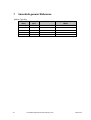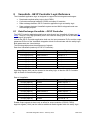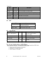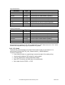
1
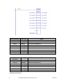
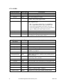
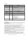
GE Intelligent Platforms Programmable Control Products VersaSafe Integration Guide, GFK-2735 February 2012 GFL-002 Warnings, Cautions, and Notes as Used in this Publication Warning Warning notices are used in this publication to emphasize that hazardous voltages, currents, temperatures, or other conditions that could cause personal injury exist in this equipment or may be associated with its use. In situations where inattention could cause either personal injury or damage to equipment, a Warning notice is used. Caution Caution notices are used where equipment might be damaged if care is not taken. Note: Notes merely call attention to information that is especially significant to understanding and operating the equipment. This document is based on information available at the time of its publication. While efforts have been made to be accurate, the information contained herein does not purport to cover all details or variations in hardware or software, nor to provide for every possible contingency in connection with installation, operation, or maintenance. Features may be described herein which are not present in all hardware and software systems. GE Intelligent Platforms assumes no obligation of notice to holders of this document with respect to changes subsequently made. GE Intelligent Platforms makes no representation or warranty, expressed, implied, or statutory with respect to, and assumes no responsibility for the accuracy, completeness, sufficiency, or usefulness of the information contained herein. No warranties of merchantability or fitness for purpose shall apply. * indicates a trademark of GE Intelligent Platforms, Inc. and/or its affiliates. All other trademarks are the property of their respective owners. ©Copyright 2011 GE Intelligent Platforms, Inc. All Rights Reserved 2 VersaSafe Integration Guide – February 2012 GFK-2735 Contact Information If you purchased this product through an Authorized Channel Partner, please contact the seller directly. General Contact Information Online technical support and GlobalCare http://www.ge-ip.com/support Additional information http://www.ge-ip.com/ Solution Provider [email protected] Technical Support If you have technical problems that cannot be resolved with the information in this guide, please contact us by telephone or email, or on the web at www.ge-ip.com/support Americas Online Technical Support www.ge-ip.com/support Phone 1-800-433-2682 International Americas Direct Dial 1-780-420-2010 (if toll free 800 option is unavailable) Technical Support Email [email protected] Customer Care Email [email protected] Primary language of support English Europe, the Middle East, and Africa Online Technical Support www.ge-ip.com/support Phone +800-1-433-2682 EMEA Direct Dial +352-26-722-780 (if toll free 800 option is unavailable or if dialing from a mobile telephone) Technical Support Email [email protected] Customer Care Email [email protected] Primary languages of support English, French, German, Italian, Czech, Spanish Asia Pacific Online Technical Support www.ge-ip.com/support Phone +86-400-820-8208 +86-21-3217-4826 (India, Indonesia, and Pakistan) Technical Support Email [email protected] (China) [email protected] (Japan) [email protected] (remaining Asia customers) Customer Care Email [email protected] [email protected] (China) 3 VersaSafe Integration Guide–February 2012 GFK-2735 1 Introduction .................................................................................................................. 7 1.1 1.2 2 Scope ..................................................................................................................................... 7 References ............................................................................................................................. 7 Overview ....................................................................................................................... 8 2.1 What is VersaSafe .................................................................................................................. 8 2.2 VersaSafe Integration Overview............................................................................................. 8 2.3 Preconditions .......................................................................................................................... 8 2.3.1 Software Requirements .................................................................................................. 8 2.3.2 Hardware Requirements ................................................................................................ 8 3 Hardware Installation – Quickstart.............................................................................. 9 3.1 4 Fieldbus Configuration .............................................................................................. 10 4.1 5 DIP Switch setting .................................................................................................................. 9 Profibus ................................................................................................................................ 10 Detailed Software Integration Steps ......................................................................... 11 5.1 Import VersaSafe integration Drawer ................................................................................... 12 5.2 Import UDTs, Logic Blocks, and Variables ........................................................................... 12 5.3 Import HMI Panels and Scripts ............................................................................................. 13 5.4 Create/Modify Safety Logic with VersaConf Safety ............................................................. 13 5.5 Import XML file ..................................................................................................................... 14 5.6 Configure RX3i Logic ........................................................................................................... 14 5.7 LPSDO and PSDx interface ................................................................................................. 16 5.7.1 Configuration ................................................................................................................ 16 5.7.2 LPSDO ......................................................................................................................... 17 5.7.3 PSDx ............................................................................................................................ 18 5.7.4 Operation ...................................................................................................................... 18 5.8 Download Targets and run Application ................................................................................ 19 5.9 Modification cycle ................................................................................................................. 19 6 Operating the VersaSafe HMI .................................................................................... 21 7 VersaSafe general Reference .................................................................................... 23 8 VersaSafe - GE IP Controller Logic Reference ......................................................... 24 8.1 Data Exchange VersaSafe – GE IP Controller ..................................................................... 24 8.2 IO Data ................................................................................................................................. 25 8.3 UDT ...................................................................................................................................... 26 8.4 Logic Blocks ......................................................................................................................... 26 8.4.1 VS_call_<Island number>_<SafeProjName> .............................................................. 26 8.4.2 VS_Island ..................................................................................................................... 27 8.4.3 VS_Download ............................................................................................................... 28 8.4.4 Conversion Subroutines ............................................................................................... 30 9 VersaSafe HMI Reference .......................................................................................... 31 9.1 Data Exchange: GE IP Controller – HMI .............................................................................. 31 9.2 Screens ................................................................................................................................ 33 9.2.1 Main VersaSafe Diagnostic Screen ............................................................................. 33 9.3 Scripts ................................................................................................................................... 33 9.4 Structures ............................................................................................................................. 33 10 5 VersaSafe Performance ............................................................................................. 34 VersaSafe Integration Guide–February 2012 GFK-2735 10.1 Transit Time from RX3i Controller to LPSDO ...................................................................... 34 10.2 Transit Time from PSDI to RX3i Controller .......................................................................... 34 6 VersaSafe Integration Guide – February 2012 GFK-2735 1 Introduction 1.1 Scope This document describes how to integrate a VersaSafe machine safety project into a PACSystems (RX3i) based automation application, using Proficy Machine Edition. Creating the safety project itself, as well as any safety related assessments, is not within the scope of this document. This document consists of two parts: part one (chapters 3 to 6) provides help for a quick start: install hardware, configure fieldbus, GE IP Controller and HMI and operate HMI. The second part contains reference information for GE IP Controller programmers and HMI designers. 1.2 References VersaSafe VersaPoint Module, IC220SDL543 User’s Manual, GFK-2730 VersaSafe VersaPoint Module, IC220SDL953 User’s Manual, GFK-2731 VersaSafe VersaPoint Module, IC220SDL753 User’s Manual, GFK-2732 VersaSafe VersaPoint Module, IC220SDL752 User’s Manual, GFK-2733 VersaSafe VersaPoint Module, IC220SDL840 User’s Manual, GFK-2734 7 VersaSafe Integration Guide–February 2012 GFK-2735 2 Overview 2.1 What is VersaSafe VersaSafe is a configurable machine safety solution, designed for mid sized machine safety applications in the range of approximately 32-128 safety IO. VersaSafe is based on VersaPoint Network Interface Units (NIUs). For the first step, VersaSafe will support Profibus. Other NIUs will follow step by step. 2.2 VersaSafe Integration Overview VersaSafe needs a GE IP Controller application logic and a fieldbus to perform communication between main GE IP Controller and VersaSafe modules, as well as for communication between the safety modules amongst each other. This is referred to also as host environment. There is no safety related requirement, neither to application logic nor to fieldbus. However the host environment must provide a cyclic, deterministic and device-consistent communication. Generally, any host environment, which is supported by a VersaPoint NIU and which is compliant to above requirements is able to run VersaSafe. This integration guide describes how to integrate VersaSafe into an RX3i/QuickPanel View/Control host environment. Steps to integrate VersaSafe into a PME/RX3i/QuickPanel View/Control project Import the VersaSafe integration drawer into Machine Edition Drag UDTs and logic blocks from the integration drawer into the RX3i logic, import the csv variable file(s) Drag the screens and scripts from the integration drawer into a PME View target, and import the csv variable file(s) and the language grid. Import an XML file into the RX3i logic, which was previously created by VersaConf Safety for each safety island Configure GE IP Controller logic for all individual safety islands 2.3 Preconditions 2.3.1 Software Requirements Proficy Machine Edition, LD PLC and View, V 7.0 SIM 7 or higher VersaConf Safety configurator V 2.7 or higher VersaSafe Integration Package: PME drawer, auxiliary files, this manual 2.3.2 Hardware Requirements 8 RX3i controller with Ethernet and Profibus Master Profibus NIU with VersaSafe modules QuickPanel View/Control VersaSafe Integration Guide – February 2012 GFK-2735 3 Hardware Installation – Quickstart This chapter shows only some fundamental steps for a quick start. For more information refer to the appropriate hardware manuals. VersaSafe modules can be installed at any VersaPoint NIU, combined with standard VersaPoint modules. For currently supported field busses see fieldbus configuration. 3.1 DIP Switch setting Each VersaSafe module must be configured by DIP switch for the correct island- and satellite number. DIP switches are only visible and operable if the module is not installed. Make sure switches are set correctly before you install the module. DIP switch LPSDO PSDx 0-2 always 0 Satellite number 1 … 5 3-7 Island number 1 … 31 Island number 1 … 31 8 always off always off 9 off : normal mode on : multiplexer mode always off 1 : 16 Words IO, max 3 satellites 2 : 24 Words IO, max 5 satellites Mode 2 500KBD 500KBD Mode Baud rate Note that multiplexer mode is not explicitly supported by this package. However you can use multiplexer mode with some simple GE IP Controller logic. Refer to hardware manuals for more information about multiplexer mode. 9 VersaSafe Integration Guide–February 2012 GFK-2735 4 Fieldbus Configuration 4.1 Profibus A PBM300 Profibus master must exist in the RX3i hardware configuration. Add as many NIUs (IC220PBI002) as your application requires. Add standard and safety modules to the NIUs. The distribution of safety modules is completely free. Safety modules of the same island can be located at the same or at different NIUs. Safety modules of different islands can be located at the same NIU or at different NIUs. Note that the one LPSDO requires 16 or 24 words of data. This may restrict the number of usable LPSDOs for one NIU due to system limitations. Double click on the modules to review and alter the assigned addresses. It is recommended to create a scheme for addressing. For example you may reserve %AI101 to %AI199 for safety island number 1 and the same for %AQ. Then the first 24 Words (101-124) are for the LPSDO. Always reserve 24 Words, even in case of a 16 Word / 3 satellites configuration. Then address 125 to 128 is for satellite 1, address 129 to 132 is satellite 2 and so on. Use the same scheme for island two with addresses 201 upward, see table below. Example: Island LPSDO (0) Sat. 1 Sat. 2 Sat. 3 Sat. 4 Sat. 5 1 101-124 125-128 129-132 133-136 137-140 141-144 2 201-224 225-228 229-232 233-236 237-240 241-244 3 301-324 325-328 329-332 333-336 337-340 341-344 4 401-424 425-428 429-432 433-436 437-440 441-444 You will need these addresses to complete the software configuration later. A csv file with variables using the above scheme for island 1 to 4 is provided for convenience. 10 VersaSafe Integration Guide – February 2012 GFK-2735 5 Detailed Software Integration Steps The integration package includes at least the following files: File Contents VersaSafe_Vxxx.zip Start-up PME project. VersaSafe Integration.zdrw PME drawer PH_VSafe_xx.csv variables to import in the GE IP Controller target VS_1.csv, VS_2.csv, VS_3.csv, VS_4.csv variables to import in the GE IP Controller target H_VSafe.csv variables to import in the HMI target VS_Language.csv Language grid entries Additional files to speed-up integration might be present. You can use any existing PME RX3i/QuickPanel View/Control project to integrate VersaSafe or you can start a new project or you can use the start-up project. The RX3i target and the QuickPanel View/Control target might be in same project or in different projects. For the steps in the next chapters it is assumed we have already an RX3i target in a PME project and a 12” QuickPanel View/Control target within the same or in different project. The following steps describe how to add VersaSafe to an existing project. Open the common (or the RX3i) project and proceed as described below: 11 VersaSafe Integration Guide–February 2012 GFK-2735 5.1 Import VersaSafe integration Drawer Locate the file VersaSafe Integration.zdrw and import it into the PME toolchest. 5.2 Import UDTs, Logic Blocks, and Variables Open the drawer “VersaSafe Integration” in the toolchest window. 1. Drag all items from the UDT folder to the UDT folder of the RX3i target. 2. In the RX3i target’s “Program Blocks” folder add a folder “VersaSafe” 3. Drag all logic blocks from the toolchest Logic folder to the VersaSafe folder. Start with conv… blocks and then add VS_Data, VS_CheckAddr, VS_Download, VS_Island and then VS_System. 12 VersaSafe Integration Guide – February 2012 GFK-2735 4. Import one of the PH_VSafe_xx.csv files to the RX3i target - variables. xx depends on the maximum number of islands you want to support. It is possible to upgrade the number islands at any time later. This step will add the diagnostic interface to QuickPanel View/Control for up to four safety islands. 5. Import the csv file VS_1.csv to the RX3i target - variables. This step will add the fieldbus interface for the first safety island. If you need more than one island, import also VS_2/3/4.csv 6. Include an unconditional call of VS_System in MAIN. Connect the “Enable” input to a condition that reflects the “OK” status of the fieldbus communication. If you are not sure, just connect an #ALW_ON. 5.3 Import HMI Panels and Scripts If you work with separate PME projects, open the QuickPanel View/Control project now and open the drawer VersaSafe Integration again. Otherwise proceed directly. 1. Import the H_VSafe.csv file to the HMI_QP12 target - variables. 2. Drag VS_LIB from toolchest LIB folder to project folder Global Functions 3. Drag all items from toolchest folder MessageGrids to project folder Message Grids. 4. Drag all panels from toolchest folder Panels to project folder Graphical Panels. 5. Include panel VS_Diag into your navigation system. You may also want to rename it and adjust vertical size or position according existing conditions. 6. Enable language translation, add three languages English(default) German and Italian 7. Open Language.csv using MS excel. Select all rows, first 3 columns, “Copy”, open the language grid in PME, click with right mouse button into the grid and choose “Paste row(s)” Note: Open the screen VS_Diag and check assignment of message grids according the following picture and update manually if it is not done automatically: VS_ErrorCode VS_Location VS_Status VS_ErrorCodeDL 5.4 Create/Modify Safety Logic with VersaConf Safety This step is only mentioned and briefly described here. For more information, see online help of VersaConf Safety. 13 VersaSafe Integration Guide–February 2012 GFK-2735 Note about naming conventions: The logic block created by VersaConf Safety has the name VS_call_x_<safety-logicname>. Where x is the island number and <safety-logic-name> is the name of the VersaConf Safety project. Block names in ME are restricted to 31 characters total. That means, the name of the safety project is limited to 21 characters. Keep in mind also restrictions about usable characters for logic blocks in ME and the fact that ME is not case sensitive. For each individual island: Create or modify safety logic. Open menu “Project” – “Check project”. When it is finished without error, you will find an XML file in the FileOutput folder of VersaConf Safety’s project folder. 5.5 Import XML file If you work with separate PME projects, open the RX3i project now. Otherwise proceed directly. For each safety island do the following steps: 1. Click with right mouse button at Program Blocks / VSafe, and choose “Import Block from File …”. 2. Navigate to the VersaConf Safety project folder, FileOutput folder; open the XML file. 3. If a Variable Conflict dialog pops up, select “Use existing variable” and confirm. After some seconds a new ST block in VSafe will appear with the name VS_call_<Island number>_<SafeProjName> 4. Open the block VS_System and add the new ST block with instance name <SafeProjName>. Call it conditionally with an NO contact the input “Enable”. 5.6 Configure RX3i Logic For each safety island block (VS_call_<Island number>_<SafeProjName>, see previous chapter) you have to attach appropriate parameters. There are 6 input and 6 output parameters, which have to be connected via fieldbus to the safety modules. Depending on the used fieldbus, it can be by address based variables or by pure symbolic variables. You can import the VS_1.csv file with referenced variables for convenience. In addition there are some input and output parameter connected to internal GE IP Controller logic and a UDT structure for HMI communication. Next picture shows an example for island # 2. 14 VersaSafe Integration Guide – February 2012 GFK-2735 Input Parameter Date Type Signal LPSDOin WORD[24] Input from LPSDO Module PSD1in WORD[4] Input from PSD Module # 1 PSD2in WORD[4] Input from PSD Module # 2 PSD3in WORD[4] Input from PSD Module # 3 PSD4in WORD[4] Input from PSD Module # 4 PSD5in WORD[4] Input from PSD Module # 5 PLCin WORD[4] Input from GE IP Controller Island UINT Island Nr VS_PH_VSafe PH_VSafe[Island]: Communication with HMI Diag Output Parameter Date Type Signal LPSDOout WORD[24] Output to LPSDO Module PSD1out WORD[4] Output to PSD Module # 1 PSD2out WORD[4] Output to PSD Module # 2 PSD3out WORD[4] Output to PSD Module # 3 PSD4out WORD[4] Output to PSD Module # 4 PSD5out WORD[4] Output to PSD Module # 5 PLCout WORD[4] Output to GE IP Controller Mandatory parameters: 15 VersaSafe Integration Guide–February 2012 GFK-2735 Island: Must be the number, which is defined in the VersaConf Safety tool and equal to DIP switch setting. Island is 1 based. Diag: Attach the array member of PH_VSafe array with index = island number. LPSDOin: 24 WORD array connected by fieldbus to the LPSDO module as input. LPSDOout: 24 WORD arrays connected by fieldbus to the LPSDO module as output. PSD1in: 4 WORD array connected by fieldbus to PSDx module #1 as input. PSD1out: 4 WORD arrays connected by fieldbus to PSDx module #1 as output. Optional parameters: PSD2..5in: 4 WORD array connected by fieldbus to PSDx modules #2-5 as input. PSD2..5out: 4 WORD arrays connected by fieldbus to PSDx modules #2-5 as output. PLCin: 4 WORD array to allow the GE IP Controller to provide enable signals for the safety logic. PLCout: 4 WORD array to allow the GE IP Controller access to signals of safety logic. You can create appropriate arrays and assign the addresses you assigned during hardware configuration, or in case the fieldbus supports symbolic variables, you use the variables created during fieldbus configuration. 5.7 LPSDO and PSDx interface User defined function blocks LPSDO & PSDx are provided as a part of integration tool chest for easy user interaction with the LPSDO & PSDx modules. These blocks are not mandatory for the Versasafe integration logic to work. They are useful in particular if status and confirmation signals shall be processed by PLC logic, not (only) by HMI. If required, these blocks can be dragged to the application logic & used. 5.7.1 Configuration 1. Drag the LPSDO block from the Versasafe Integration tool chest to the logic. 2. Call the LPSDO UDFB in the logic and assign an instance name to it. 3. Pass the required island number to “IslandNr” input and pass the configured PLCIn parameter of VS_Call_xx block in VS_System for specified island number to “PLCIn” input. 4. All other bool inputs should be OFF and other inputs should be 0. 5. Assign coils with appropriate name to the outputs. 6. After the download of target and CPU placed in Run IO Enabled mode, make sure that VersaSafe integration logic is being called. 16 VersaSafe Integration Guide – February 2012 GFK-2735 5.7.2 LPSDO Input Parameter Date Type Description IslandNr UINT Island number configured in LPSDO OpAck BOOL Operator acknowledge for failsafe communication. DevAck BOOL Error acknowledge for LPSDO. Restart BOOL Restart download of safety logic from GE IP Controller to LPSDO. Rising edge triggered input ConfirmDownload BOOL Confirm download of different logic to LPSDO. Rising edge triggered input. Note: As a safety requirement, it is mandatory that “ConfirmDownload” input should not be turned ON programmatically and it has to be turned ON manually using a physical push button input or HMI push button input from user. AppAck WORD Application acknowledge bits 0 - 15. EnableOut BYTE Enable output signals for LPSDO module. WORD[4] Configured PLCIn parameter of VS_Call_xx block in VS_System for specified island number. PLCIn Date Type Output Parameter 17 Description InvalidIsland BOOL Input island number is invalid OutStatus BYTE LPSDO output status. AppDiag BYTE Status of application diagnostic bits 0 – 7. PLCLogicActive BOOL VersaSafe integration logic is executed DownloadActive BOOL Download of safety logic from GE IP Controller to LPSDO is in progress DownloadProgress INT Download progress percentage DiffLogicDetected BOOL Safety logic in LPSDO is different from loaded project in GE IP Controller RoutingEnabled BOOL Communication between VersaSafe modules is executed by GE IP controller RoutingStatus BOOL Communication status between VersaSafe modules CommErr BOOL Communication error is detected by the integration logic PowerCycleReq BOOL Power cycle of LPSDO is required AnyDevErr BOOL Any device error OpAckReq BOOL Operator acknowledge is required SysStatus WORD Island status. 9000H = Running, 9001H = No project, 9002H = Loading, 9003H = Stopped. ModErrorCode WORD Module Error Code. Refer LPSDO module manual VersaSafe Integration Guide–February 2012 GFK-2735 5.7.3 PSDx Input Parameter Date Type Description IslandNr UINT Island number configured in LPSDO SatelliteNr UINT Satellite number of the island DevAck BOOL Error acknowledge for PSDx. EnableOut BYTE Enable output signals for PSDO module. Applicable only for PSDO module. For PSDI module provide 0 to this input. WORD[4] Configured PLCIn parameter of VS_Call_xx block in VS_System for specified island number. PLCIn Date Type Output Parameter Description InvalidIsland BOOL Input island number is invalid InvalidSatellite BOOL Input satellite number is invalid InOutStatus BYTE PSDI input / PSDO output status. CommStatus BYTE Bit 0 - 3 refers to Module Communication Status. 0000 = OK 0001 = OK, but not yet started 0010 = DIP switch error 0011 = not connected 0100 = Invalid module type detected 1000 = not configured ErrorCode WORD Module Error Code. Refer to the individual module manual 5.7.4 Operation Steps to download safety logic from RX3i Controller to Safety logic module (LPSDO) using ‘LPSDO’ UDFB. Note: These steps are not mandatory if HMI/View is used as mentioned in above sections. 1. The “PLCLogicActive” output should be ON. If it is OFF then either the VersaSafe integration steps is not followed correctly or integration logic is not called. 2. Once the “PLCLogicActive” is ON, the “DiffLogicDetected” output will be ON if the safety logic in RX3i Controller is different from safety logic in LPSDO module. 3. If “DiffLogicDetected” output is ON, turn ON the “ConfirmDownload” input for one scan so that download starts and the “DownloadActive” will be ON and the “DownloadProgress” gives the progress percentage of the download. Note: As a safety requirement, it is mandatory that “ConfirmDownload” input should not be turned ON programmatically and it has to be turned ON manually using a physical push button input or HMI push button input from user. 4. After the completion of download, if the “OpAckReq” output in ON then turn ON the “OpAck” input till the “OpAckReq” output turns OFF. 5. Now the “SysStatus” output should be 9000H, “RoutingEnabled” & “RoutingStatus” outputs should be ON which indicates that the safety logic of that corresponding island is running and no errors are present. If not, just turn ON “Restart” input for one scan. 18 VersaSafe Integration Guide – February 2012 GFK-2735 6. If the “OpAckReq” output in ON then turn ON the “OpAck” input till the “OpAckReq” output turns OFF. 7. Even now if any of “RoutingEnabled” & “RoutingStatus” outputs is OFF then check for any error output being set in LPSDO block outputs and check the individual satellite (PSDO/PSDI) status using PSDx block. 5.8 Download Targets and run Application Now you can validate, download and start the targets. 5.9 Modification cycle If the safety engineer has decided to modify the safety logic and created a new XML file, the XML file must be imported again. If the number of satellites has changed, you may need also to update the parameters. If the number of islands has been increased, check the following items: The array size of PH_VSafe must be at least number of islands plus two. The array size of H_VSafe must be at least number of islands plus one. If you increase the array size of PH_VSafe, make sure all elements have the publish property equal “External” If you work with separate PME projects, open the RX3i project now. 1. Click with right mouse button at Program Blocks / VSafe, and choose “Import Block from File …”. 2. Navigate to the VersaConf Safety project folder, FileOutput folder; open the XML file. 3. If a Variable Conflict dialog pops up, select “Use existing variable” and confirm. After some seconds the ST block with the name VS_call_<Island number>_<SafeProjName> is updated. Typically you will be able to do a run-mode-store now to update the RX3i logic. But this will not automatically invoke the updated safety logic. To trigger this you have the following options Stop/start (or power cycle) the RX3i Power cycle the remote station, where the LPSDO is part of Press restart on the HMI screen In all cases, the new safety logic is initialized in RX3i memory, and is compared with the actual logic in the LPSDO. As we have modified the logic, a difference is found and a dialog pops up at the HMI, to show some relevant data of the project loaded in the LPSDO versus the new actual updated project. The operator must explicitly confirm that he wants to update the safety logic. This is part of the safety policy. Additionally the GE IP Controller programmer (and the safety engineer) can look at any time into the ST block. There is a comprehensive comment section showing all relevant parameters of the actual safety logic (like time of last change, version etc). Example: // // // // // // // // 19 ================================================= ST init block for VersaSafe PACSystem output format V 1.0 Island: 2 ================================================= =================== Project Information VersaSafe Integration Guide–February 2012 GFK-2735 // =================== // Application Name: VersaConf Safety 2.7 // Build Number: 374 // Project Developer (Windows Login Name): 113004127 // // ======= // Project // ======= // // Project (Program and Device Parametrization) // -------------------------------------------// Project Name: AckTestBig // Path to Project: D:\Documents and Settings\113004127\My Documents\AppProj\Applied Solution\VersaSafe\SafeConf // Last changed: 28.03.2011 11:34:27 // Project CRC: E0B9B5A6 // // Archival Storage (Project and Documentation) // -------------------------------------------// Project Printed: No // Project Archived: No // // ================= // Operating Company // ================= // // Address of Application Location // ------------------------------// Same as Operating Company: No // // ====== // Checks // ====== // // Wiring // -----// Input Signals: Not checked // Output Signals: Not checked // // Timing // -----// Output Signals: Not checked // // Devices // ------// Compliancy: Not checked // Device Parameters: Not checked // // ======= // History // ======= // // Previous Project // ---------------// Predecessor exists?: No // // =========== // Project CRC // =========== // // CRCs // ---// Project Header CRC: 90D01AD7 // Logical Block CRC: F75C11D3 // Address Block CRC: 0D27D1B3 // Project Header Time Stamp: 28.03.2011 11:34:27 20 VersaSafe Integration Guide – February 2012 GFK-2735 6 Operating the VersaSafe HMI VersaSafe modules do not have any user operational controls and they have only a few LEDs to indicate the current state. Moreover they are often hidden somewhere in a cabinet. A convenient tool to watch the status and operate the modules is the HMI screen which is included in the integration package. It shows the status of the modules itself, of all physical IO, and of GE IP Controller interface signals. In case of any safety event it will show a text message to indicate the location and the cause of the event. VersaSafe status screen, elements for module status: Module type Module status and error display Output enable status (only for output modules Unconfigured satellite IO status Error acknowledge button For each module we have: Module type display (LPSDO, PSDI, PSDO) Module status display (configured, communicating, safety errors: text and location) IO status display (physical IO status) Output enable status display (only for LPSDO and PSDO) Error acknowledge button to confirm any safety event 21 VersaSafe Integration Guide–February 2012 GFK-2735 VersaSafe status screen, elements for island status: System status Island application data status System status flags Island selector button to display header Island status flags button to restart 22 VersaSafe Integration Guide – February 2012 GFK-2735 7 VersaSafe general Reference Module Type IDs: Module ID (hex) 23 Module Module ID (dec) Length of I-par block (Byte) 0x10 16 PSDI 26 0x20 32 PSDO 32 0x30 48 PSDOR 20 0x40 64 PSDO 4/4 20 0x50 80 LPSDO 32 VersaSafe Integration Guide–February 2012 GFK-2735 8 VersaSafe - GE IP Controller Logic Reference The VersaSafe application logic is designed to support the following data exchanges: Download compiled safety logic to the LPSDO Cyclic data exchange between LPSDO and safety IO modules Data exchange between GE IP Controller application logic and safety logic Data exchange between VersaSafe system and an HMI for diagnostic and user acknowledge purpose. 8.1 Data Exchange VersaSafe – GE IP Controller The GE IP Controller application shall never write directly into VersaSafe IO data (see IO Data). There is a very high probability that in this case the safety goes into a safe state, switching off all outputs. Instead the GE IP Controller application shall use the input parameter PLCin and the output parameter PLCout of the VersaSafe integration block to communicate with the safety logic. Both parameters are 4 word arrays. The following tables show the assignment of signals. Data from VersaSafe (read only for GE IP Controller): Parameter Device Signal PLCout[0].X[00-07] LPSDO Output 0 - 7 PLCout[0].X[08-15] PSDx Satellite 1 In/Output 0 - 7 PLCout[1].X[00-07] PSDx Satellite 2 In/Output 0 – 7 PLCout[1].X[08-15] PSDx Satellite 3 In/Output 0 – 7 PLCout[2].X[00-07] PSDx Satellite 4 In/Output 0 – 7 PLCout[2].X[08-15] PSDx Satellite 5 In/Output 0 - 7 PLCout[3].X[00-07] LPSDO App-Diag 0 - 7 App-Diag Signals (8 bit) can be inserted in the safety logic, so that the GE IP Controller logic is aware of internal safety signals. Data to VersaSafe: Parameter Device Signal PLCin[0].X[00-07] LPSDO Enable Output 0 - 7 PLCin[0].X[08-15] PSDx Satellite 1 Enable Output 0 - 7 PLCin[1].X[00-07] PSDx Satellite 2 Enable Output 0 – 7 PLCin[1].X[08-15] PSDx Satellite 3 Enable Output 0 – 7 PLCin[2].X[00-07] PSDx Satellite 4 Enable Output 0 – 7 PLCin[2].X[08-15] PSDx Satellite 5 Enable Output 0 - 7 PLCin[3].X[00-07] LPSDO App-Ack 00 - 07 PLCin[3].X[08-15] LPSDO App-Ack 08 - 15 Enable Output signals do have only an effect for output modules (LPSDO, PSDO). App-Ack signals (16 bit) can be used as additional enable signals within the safety logic. 24 VersaSafe Integration Guide – February 2012 GFK-2735 8.2 IO Data VersaSafe Modules represent an analog IO module within the given fieldbus. They can have either 4 or 16 or 24 words of input and output. The input size is always equal to the output size. Do not use this data directly, it is only shown for reference here. Use the GE IP Controller interface instead. The logic module (referred to as “LPSDO”) has 16 or 24 words of IO, depending on DIP switch setting. All IO modules (referred to as PSDI and PSDO) have 4 words of IO. The following tables show the usage of the 4 words of IO modules and the first 4 words of an LPSDO. Further words of the LPSDO are used for data exchange between IO and logic module or for download of safety logic to the logic module, depending on the state of the system. For more information see chapter “Safety Bridge System” of module manuals. VersaSafe is a big endian system, while PACSystem is a little endian system, so care must be taken when accessing bytes. Input Data, big endian ordered. The second column shows the byte # for a little endian (“Intel”) system. Byte # # LPSDO PSDI PSDO 0 1 Dev-Diag (hi) Dev-Diag (hi) Dev-Diag (hi) 1 0 Dev-Diag (lo) Dev-Diag (lo) Dev-Diag (lo) 2 3 App-Diag Input-Data Protocol 3 2 Output-Data Protocol Protocol 4 5 Comm.-Protocol Protocol Protocol 5 4 Comm.-Protocol Protocol Protocol 6 7 Comm.-Protocol Protocol Reserved 7 6 Comm.-Protocol Reserved Output-Data Output Data, big endian ordered. The second column shows the byte # for a little endian (“Intel”) system. 25 Byte # # LPSDO PSDI 0 1 Dev-Ack Dev-Diag (hi) Dev-Diag (hi) 1 0 App-Ack Dev-Diag (lo) Dev-Diag (lo) 2 3 App-Ack Protocol Output-Data 3 2 Enable-Out Protocol Protocol 4 5 Comm.-Protocol Protocol Protocol 5 4 Comm.-Protocol Protocol Protocol 6 7 Comm.-Protocol Reserved Reserved 7 6 Comm.-Protocol Reserved Enable-Out VersaSafe Integration Guide–February 2012 PSDO GFK-2735 Explanation: Item Direction Description Dev-Diag VS -> PLC Device diagnostic data, see module manual App-Diag VS -> PLC Application data generated by safety logic Dev-Ack PLC -> VS Device acknowledge, see module manual App-Ack PLC -> VS Application data from GE IP Controller to safety logic Enable-Out PLC -> VS Enable output, used if individually enabled by HW configuration Input-Data VS -> PLC Status data from safe inputs Output-Data VS -> PLC Status data from safe outputs Comm.-Prot. Both Short communication protocol Protocol Both Safety Bridge routing protocol 8.3 UDT UDT Purpose VS_Cfg Compiled safety logic: header block, address block, logic block VS_CfgLB Logic block for VS_Cfg VS_PH_VSafe Communication object for HMI 8.4 Logic Blocks Block Type Lang. Purpose VS_call_<Island number>_<SafeProjName> UDFB ST Initialize compiled safety logic and call VS_Island, created as XML by VersaConf Safety VS_Island UDFB LD Safety island management block VS_Download UDFB ST Communicate with LPSDO VS_CheckAddr PB LD Verify correct DIP settings VS_Data PB ST Extract data for HMI and GE IP Controller conv….. PB LD Various auxiliary conversion subroutines 8.4.1 VS_call_<Island number>_<SafeProjName> This ST block is created by VersaConf Safety as XML, and is imported into PME. Never change this block in any way. The contents of the block are: Safety project documentation as comments Initialisation of compiled safety logic Call an instance of VS_Island 26 VersaSafe Integration Guide – February 2012 GFK-2735 Input Parameters: Parameter Type LPSDOin BYTE[48] 24 Words input from LPSDO module (fieldbus) PSDx1in BYTE[4] 2 Words input from PSDx satellite 1 (fieldbus) PSDx2in BYTE[4] 2 Words input from PSDx satellite 2 (fieldbus) PSDx3in BYTE[4] 2 Words input from PSDx satellite 3 (fieldbus) PSDx4in BYTE[4] 2 Words input from PSDx satellite 4 (fieldbus) PSDx5in BYTE[4] 2 Words input from PSDx satellite 5 (fieldbus) PLCin WORD[4] 4 Words input from GE IP Controller application Island INT Number of safety island (1...31) Diag UDT Diagnostic data, shall be published external for HMI Output Parameters: Parameter Type LPSDOout BYTE[48] 24 Words output to LPSDO module (fieldbus) PSDx1out BYTE[4] 2 Words output to PSDx satellite 1 (fieldbus) PSDx2out BYTE[4] 2 Words output to PSDx satellite 2 (fieldbus) PSDx3out BYTE[4] 2 Words output to PSDx satellite 3 (fieldbus) PSDx4out BYTE[4] 2 Words output to PSDx satellite 4 (fieldbus) PSDx5out BYTE[4] 2 Words output to PSDx satellite 5 (fieldbus) PLCout WORD[4] 4 Words output to GE IP Controller application All parameters are passed to VS_Island. Additionally the UDT based structure “Conf” which contains the compiled safety logic, is passed to VS_Island. 8.4.2 VS_Island The block VS_Island manages one island. Each island needs its own instance. It is automatically created within VS_call_<Island number>_<SafeProjName>. Functions of this block: insert island number in compiled logic (required as part of the safety policy) check module address (DIP setting) for each module Call VS_Download to communicate with LPSDO Map GE IP Controller and HMI data to VersaSafe data Move data from/to LPSDO <-> PSD 27 VersaSafe Integration Guide–February 2012 GFK-2735 Input Parameters: Parameter Type LPSDOin BYTE[48] 24 Words input from LPSDO module (fieldbus) PSDx1in BYTE[4] 2 Words input from PSDx satellite 1 (fieldbus) PSDx2in BYTE[4] 2 Words input from PSDx satellite 2 (fieldbus) PSDx3in BYTE[4] 2 Words input from PSDx satellite 3 (fieldbus) PSDx4in BYTE[4] 2 Words input from PSDx satellite 4 (fieldbus) PSDx5in BYTE[4] 2 Words input from PSDx satellite 5 (fieldbus) PLCin WORD[4] 4 Words input from GE IP Controller application Island INT Number of safety island (1...31) Diag UDT Diagnostic data, shall be published external for HMI Conf UDT Compiled safety logic Output Parameters: Parameter Type LPSDOout BYTE[48] 24 Words output to LPSDO module (fieldbus) PSDx1out BYTE[4] 2 Words output to PSDx satellite 1 (fieldbus) PSDx2out BYTE[4] 2 Words output to PSDx satellite 2 (fieldbus) PSDx3out BYTE[4] 2 Words output to PSDx satellite 3 (fieldbus) PSDx4out BYTE[4] 2 Words output to PSDx satellite 4 (fieldbus) PSDx5out BYTE[4] 2 Words output to PSDx satellite 5 (fieldbus) PLCout WORD[4] 4 Words output to GE IP Controller application 8.4.3 VS_Download This block does the communication with LPSDO for download of compiled logic and LPSDO status. 28 VersaSafe Integration Guide – February 2012 GFK-2735 State Machine: 0: Reset Status = NO PROJ 310: Read Header not equal 330: reload header 315: Wait for confirmation equal accepted 320: Download (LPSDO initiated) error Download complete Pseudo Code for extracting the module ID (* It is assumed the logic block consists of a zero-based DW array LogicBlockDW *) ByteOffset := LogicBlockDW[2].W0 + LogicBlockDW[2].W1 + 13 ; DWoffset := ByteOffset / 4 ; ByteNr := ByteOffset Mod 4 ; ModuleCount := BYTE_TO_INT (LogicBlockDW[DWoffset].B[ByteNr]) ; ByteOffset := ByteOffset + 4 ; For i := 0 To ModuleCount-1 Do DWoffset := ByteOffset / 4 ; ByteNr := ByteOffset Mod 4 ; ModuleID[i] := BYTE_TO_INT (LogicBlockDW[DWoffset].B[ByteNr]) ; Case ModuleID[i] Of 16: (* PSDI *) ByteOffset := ByteOffset + 16; 32,80: (* PSDO, LPSDO *) ByteOffset := ByteOffset + 32; 48,64: (* PSDOR, PSDO 4/4 *) ByteOffset := ByteOffset + 20; End_Case; End_For; 29 VersaSafe Integration Guide–February 2012 GFK-2735 8.4.4 Conversion Subroutines PB 30 Purpose conv10DW2Bytes converts 10 DWORDS to 40 byte convByte2Int convert one byte to an integer convBytes2DW converts 4 Bytes to a DWORD convDW2Byte extracts one byte from a DWORD convDW2Ws converts one DWORD to two WORDs VersaSafe Integration Guide – February 2012 GFK-2735 9 VersaSafe HMI Reference 9.1 Data Exchange: GE IP Controller – HMI Data exchange between GE IP Controller and HMI is performed by arrays of structures. On GE IP Controller side the structure is implemented as UDT. The variable name is PH_VSafe. Array member index zero is unused. Island 1 uses array member index 1 and so on. All variables (except unused index 0) must have their Publish property equal External, to be able to communicate by symbolic SRTP. On HMI side it is a corresponding toolchest structure. The variable name is H_VSafe. Array member index zero is used as indirect variable to animate the screen elements. Higher indices are connected to the corresponding GE IP Controller variables as GE IP Controller Access variables. Members of communication structure: Element PLC Type HMI Type ComDiag WORD[6] DINT[6] Island communication Status Ack DWORD DINT Application data from Island HeaderLPSDO DWORD[10] DINT[10] Project Header actually stored in LPSDO HeaderProj DWORD[10] DINT[10] Project Header from compiled safety logic Data DWORD[6] DINT[6] Data from modules (1 DWORD per Sat.) Status DWORD[6] DINT[6] Status from modules (1 DWORD per Sat.) DevAck BOOL[16] BOOL[16] Device acknowledge signals ComDiag: Element Type Signal ComDiag[0].X[0] BOOL PLC Logic Active VersaSafe integration logic is executed ComDiag[0].X[1] BOOL Download active Download of compiled safety logic from GE IP Controller to LPSDO is in progress ComDiag[0].X[2] BOOL Different logic detected Safety logic in LPSDO is different from loaded project in GE IP Controller ComDiag[0].X[3] BOOL Routing Enabled Communication between VersaSafe modules is executed by the GE IP Controller. ComDiag[0].X[4] BOOL Comm. error Any error detected by the integration logic ComDiag[1] WORD LPSDO Byte[4] LPSDO communication object or FF=error ComDiag[2] WORD LPSDO Byte[5] LPSDO status ComDiag[3] WORD LPSDO Byte[6] LPSDO status ComDiag[4] WORD LPSDO Byte[7] LPSDO status ComDiag[5] INT Progress Download progress Bits 0-7 of ComDiag[0] are dedicated to show the status of GE IP Controller integration logic. The rest of ComDiag reflects the status of the LPSDO, once the integration logic is executing and the LPSDO is communicating. 31 VersaSafe Integration Guide–February 2012 GFK-2735 Status: Element Type Signal Status[0].X[11] BOOL OAR Operator Acknowledge Required Status[0].X[12] BOOL PUR Power Up Requested Status[0].X[13] BOOL Error Any Device Error Status[0].X[15] BOOL COK Communication OK Status[i].X[00-07] BOOL Module Type 1 Byte Status[i].X[16-27] BOOL Module error code See individual module manual Status[i].X[28-31] BOOL Module comm. status 0000 = OK 0001 = OK, but not yet started 0010 = DIP switch error 0011 = not connected 0100 = Invalid module type detected 1000 = not configured 3 1 3 0 2 9 2 8 2 7 2 6 2 5 Status 2 4 2 3 2 2 2 1 2 0 1 9 1 8 1 7 1 6 Module Error Code 1 5 1 4 1 3 1 2 1 1 1 0 0 9 0 8 0 7 0 6 Unused 0 5 0 4 0 3 0 2 0 1 0 0 Module Type Data: Element Type Signal Data[i].X[00-15] BOOL Error Code See individual module manual Data[i].X[16-23] BOOL Output Enable Only LPSDO and PSDO. Data[i].X[24-31] BOOL IO data DevAck: Element 32 Description DevAck[0] Error acknowledge for LPSDO DevAck[1..5] Error acknowledge for Satellites 1-5 DevAck[6] Reserved DevAck[7] Operator acknowledge for failsafe communication DevAck[8] Restart download of safety logic from GE IP Controller to LPSDO DevAck[9] Confirm download of different logic DevAck[10..15] Reserved VersaSafe Integration Guide – February 2012 GFK-2735 9.2 Screens 9.2.1 Main VersaSafe Diagnostic Screen Element Type Visibility Animation Module Header Text - Module Type Error Header 1 (LPSDO) Message Anim. L_VS_PSDxValid[S] Data[0].X[14] Error Header 1 (PSDx) Message Anim. L_VS_PSDxValid[S] Data[S].X[15] Island Nr. (LPSDO) Text Data[0].X[14] (Data[S] BAND 248) / 8 Island Nr. (PSDx) Text Data[S].X[14] AND NOT Data[S].X[15] (Data[S] BAND 248) / 8 Error Code Text Message Grid - L_VS_ErrCode[S] Error Header 2 Text L_VS_PSDxValid[S] Data[0].X[14] Satellite Nr (LPSDO) Text Data[0].X[14] Data[0] BAND 7 Satellite Nr (PSDx) Text Data[S].X[14] AND NOT Data[S].X[15] Data[S] BAND 7 Error Location Text Message Grid - L_VS_ErrLoc[S] IO Status Rectangle[8] - Data[S].X[24-31] Enable Output Rectangle[8] - Data[S].X[16-23] App Diag Data Rectangle[8] - Ack.X[00-07] App Ack Data Rectangle[16] - Ack.X[16-31] Ack Error Button - DevAck[S] Op Ack Button Data[0].X[11] DevAck[07] 9.3 Scripts Global Functions script: VS_LIB Sub comment DWORD2STRING (dw, s) converts a DWORD to a string ErrorDecodePSDx (Status, ErrLoc, ErrCode) decodes error codes from PSDIx ErrorDecodeLPSDO (Status, ErrLoc, ErrCode) decodes error codes from LPSDO 9.4 Structures See Data Exchange VersaSafe – GE IP Controller 33 VersaSafe Integration Guide–February 2012 GFK-2735 10 VersaSafe Performance The time to exchange process data between the controller and the devices of VersaSafe islands are as follows: 10.1 Transit Time from RX3i Controller to LPSDO The time to transfer data from RX3i Controller to LPSDO output is calculated according to the below formula: tLPSDO = {(tController + tProfibus + tNIU) x 1.5} + tSafetyLogic where, tLPSDO tController tProfibus tNIU tSafetyLogic Transit time from RX3i controller to LPSDO output in ms GE IP Controller sweep time in ms Profibus cycle time in ms NIU reaction time in ms Safety logic scan time: tSafetyLogic = 8 ms (max) tNIU = 2 x tt + 2 x tC tt Station transmission time in ms tC NIU Conversion time: tC = 2 ms tt = [1.15 x 13 x (8+n) + 3a] x tb + ts + 2tp n Number of user data bytes a Number of modules on NIU tb Bit duration: tb = 0.002ms at 500 kbit/s ts Software runtime: ts = 0.7 ms tp Runtime on cable: tp = 0.016 ms/km 10.2 Transit Time from PSDI to RX3i Controller The time to transfer data from PSDI input to RX3i Controller when the safety input transitions from ON to OFF is calculated according to the below formula: tPSDI1-0 = {(tController + tProfibus + tNIU) x 1.5} + tFilter where, tPSDI1-0 tController tProfibus tNIU tFilter 34 Transit time from PSDI input (1 to 0) to RX3i controller in ms GE IP Controller sweep time in ms Profibus cycle time in ms NIU reaction time in ms: Refer Section 10.1 Input filter time (in ms) configured in VersaConf Safety tool VersaSafe Integration Guide – February 2012 GFK-2735 The time to transfer data from PSDI input to RX3i Controller when the safety input transitions from OFF to ON is calculated according to the below formula: tPSDI0-1 = {(tController + tProfibus + tNIU) x 1.5} + tFilter + tSafetyTest where, tPSDI0-1 tController tProfibus tNIU tFilter tSafetyTest 35 Transit time from PSDI input (0 to 1) to RX3i controller in ms GE IP Controller sweep time in ms Profibus cycle time in ms NIU reaction time in ms: Refer Section 10.1 Input filter time (in ms) configured in VersaConf Safety tool Safety relevant test time in PSDI: tSafetyTest = 22 ms (max) VersaSafe Integration Guide–February 2012 GFK-2735