1
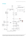
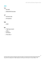
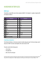
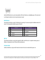
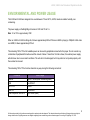
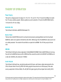
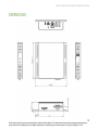
HARDWARE MANUAL
LS322, LS422
BrightSign, LLC. 16780 Lark Ave., Suite B Los Gatos, CA 95032 | 408-852-9263 | www.brightsign.biz
1
TABLE OF CONTENTS
Overview ............................................................................................................................... 1
Block Diagram ......................................................................................................................................... 2
LS322...................................................................................................................................................... 3
LS422...................................................................................................................................................... 4
Hardware Interfaces ............................................................................................................. 5
HDMI Output ........................................................................................................................................... 5
3.5mm Stereo Connectors ...................................................................................................................... 5
SPDIF (TOSLink) Connector .................................................................................................................. 6
USB Host Ports ....................................................................................................................................... 6
DA15 GPIO ............................................................................................................................................. 6
RJ45 Ethernet ......................................................................................................................................... 8
SD Port ................................................................................................................................................... 8
On-Board LEDs ....................................................................................................................................... 8
Enviornmental and Power Usage .......................................................................................9
Theory of Operation ...........................................................................................................10
Power Supply ........................................................................................................................................ 10
BCM7208 CPU ..................................................................................................................................... 10
Built-in Flash ......................................................................................................................................... 10
SDRAM ................................................................................................................................................. 10
Audio Outputs ....................................................................................................................................... 10
On-Board Switch ................................................................................................................................... 11
Reset Switch/GPIO Button .................................................................................................................... 11
NAND Flash .......................................................................................................................................... 11
Ethernet ................................................................................................................................................ 11
USB 2.0................................................................................................................................................. 11
Dimensions .........................................................................................................................12
Recommended Mounting Procedure ...............................................................................13
LS322, LS422 User Manual and Operations Guide
OVERVIEW
The LS322 and LS422 are commercial-grade media players that enable consistent, high-quality
demonstration of A/V content in retail environments. This hardware reference manual specifies the
hardware interfaces on the LS322 and LS422.
All information provided in this reference manual applies to products under development. The characteristics and specifications of these products are subject to
change without notice. BrightSign assumes no obligation regarding future manufacturing unless otherwise agreed to in writing. © BrightSign LLC, 2015
1
LS322, LS422 User Manual and Operations Guide
Block Diagram
All information provided in this reference manual applies to products under development. The characteristics and specifications of these products are subject to
change without notice. BrightSign assumes no obligation regarding future manufacturing unless otherwise agreed to in writing. © BrightSign LLC, 2015
2
LS322, LS422 User Manual and Operations Guide
LS322
Front
•
•
DA15 GPIO
SD/SDHC/SDXC flash card slot
Left
•
•
GPIO service button
GPIO reset button
Right
•
USB 2.0
Back
•
•
•
•
12V@1A power connector
SPDIF out
RJ45 Ethernet
3.5mm audio out
All information provided in this reference manual applies to products under development. The characteristics and specifications of these products are subject to
change without notice. BrightSign assumes no obligation regarding future manufacturing unless otherwise agreed to in writing. © BrightSign LLC, 2015
3
LS322, LS422 User Manual and Operations Guide
LS422
Front
•
•
DA15 GPIO
SD/SDHC/SDXC flash card slot
Left
•
•
GPIO service button
GPIO reset button
Right
•
USB 2.0
Back
•
•
•
•
•
12V@1A power connector
SPDIF out
RJ45 Ethernet
HDMI out
3.5mm audio out
All information provided in this reference manual applies to products under development. The characteristics and specifications of these products are subject to
change without notice. BrightSign assumes no obligation regarding future manufacturing unless otherwise agreed to in writing. © BrightSign LLC, 2015
4
LS322, LS422 User Manual and Operations Guide
HARDWARE INTERFACES
HDMI Output
The LS422 has a single HDMI connector that is compliant with HDMI 1.3 A/V standards. It is capable of outputting 1080i
and 720p video resolutions.
pin
Description
pin
Description
1
TX2p
2
Ground
3
TX2n
4
TX1p
5
Ground
6
TX1n
7
TX0p
8
Ground
9
TX0n
10
TXCp
11
Ground
12
TXCn
13
CEC
14
NC
15
DDC SCL
16
DDC SDA
17
Ground
18
+5V DDC
19
HPD (Hot Plug Detect)
--
3.5mm Stereo Connectors
The LS322 and LS422 have a 3.5mm stereo connector for variable analog audio output. The full-scale voltage output of
the audio is 2V RMS. The minimum load impedance of the audio connector is 32Ω.
The audio connector has the following pinout:
•
•
•
Tip: Left audio
Ring: Right audio
Base: Ground for audio signal
All information provided in this reference manual applies to products under development. The characteristics and specifications of these products are subject to
change without notice. BrightSign assumes no obligation regarding future manufacturing unless otherwise agreed to in writing. © BrightSign LLC, 2015
5
LS322, LS422 User Manual and Operations Guide
SPDIF (TOSLink) Connector
The LS322 and LS422 have a SPDIF connector capable of outputting 16-bit, 48 kHz (AC3 5.1 encoded) stereo audio
streams. Muting this connector produces digital silence.
USB Host Ports
The LS322 and LS422 each have a single USB 2.0 host port capable of providing 500mA of power. Each port also
supports HID, and devices can be hot swapped without the need to reboot.
The following table illustrates the pinout of the USB host port:
pin
Description
pin
Description
1
VBUS
2
D-
3
D+
4
Ground
DA15 GPIO
The LS322 and LS422 have a DA15 female switch/led connector. This connector allows the player to control external
LEDs or other devices requiring 24mA of current or less.
Connect the LED outputs to the LED ANODE and connect the LED CATHODE to the ground. If you want to connect
another device, then the output is capable of sourcing or sinking up to 3.3V at 24mA, but there is a series resistor of 100Ω
in each line.
The connector also allows the connecting of external contact closures to the ground. In order to connect a switch, connect
one side of the switch to the switch input, and connect the other side to one of the ground pins on the DA15 connector.
The connector can also supply 3.3V at up to 500mA to an external device. The 3.3V output is polyfuse-protected and can
source up to 500mA.
All information provided in this reference manual applies to products under development. The characteristics and specifications of these products are subject to
change without notice. BrightSign assumes no obligation regarding future manufacturing unless otherwise agreed to in writing. © BrightSign LLC, 2015
6
LS322, LS422 User Manual and Operations Guide
If one BrightSign player is driving the inputs on another BrightSign player, then you can drive at most three inputs from
one output. The following calculations explain this limitation:
Note: The GPIO outputs have 100Ω series resistors; the GPIO inputs have 1K pullup resistors to 3.3V; and the input
threshold on the 541 chips is 2V high and .8V low. The high voltage is not problematic, but the low voltage can be if there
are too many inputs connected to one output.
1 out driving 1 in
V=3.3*100/(100+1,000)=0.3
1 out driving 2 in
V=3.3*100/(100+500)=0.55
1 out driving 3 in
V=3.3*100/(100+333.3)=0.76
1 out driving 4 in
V=3.3*100/(100+250)=.94 (This is too high, so the
maximum is one output driving three inputs)
The following table illustrates the pinout of the DA15 on LS players:
pin
Description
pin
Description
1
IR blaster input
2
Ground
3
Button 6 I/O
4
Button 5 I/O
5
Button 3 I/O
6
Ground
7
Button 1 I/O
8
+3.3V output at 500mA
9
Ground
10
Button 7 I/O
11
Ground
12
Button 4 I/O
13
Button 2 I/O
14
Ground
15
Button 0 I/O
--
--
Here is the DA15 female connector as viewed from the front:
All information provided in this reference manual applies to products under development. The characteristics and specifications of these products are subject to
change without notice. BrightSign assumes no obligation regarding future manufacturing unless otherwise agreed to in writing. © BrightSign LLC, 2015
7
LS322, LS422 User Manual and Operations Guide
A button/LED/IR board can be used to demonstrate the GPIO and IR functions on a BrightSign player. This board is built
by a third-party manufacturer and can be purchased upon request.
RJ45 Ethernet
The LS322 and LS422 have a single 10/100 RJ45 port for networking. The maximum length for the Ethernet cable is 100
meters. The following table illustrates the pinout of the RJ45:
pin
Description
pin
Description
1
TX+
2
TX-
3
RX+
4
RC to ground
5
RC to ground
6
RX-
7
RC to ground
8
RC to ground
SD Port
The LS322 and LS422 have a card slot that supports SD, SDHC, and SDXC cards. It is capable of streaming video at
25Mbps or streaming three stereo PCM audio tracks simultaneously.
On-Board LEDs
LS322 and LS422 have a single red LED located on the side of the device to indicate that the power is on.
All information provided in this reference manual applies to products under development. The characteristics and specifications of these products are subject to
change without notice. BrightSign assumes no obligation regarding future manufacturing unless otherwise agreed to in writing. © BrightSign LLC, 2015
8
LS322, LS422 User Manual and Operations Guide
ENVIORNMENTAL AND POWER USAGE
The LS322 and LS422 are designed to be used between 0°C and 40°C, at 90% maximum relative humidity, noncondensing.
The power supply on the BrightSign LS series is 12W and 12V at 1A.
Note: 1A at 12V is approximately 12W.
When an LS322 or LS422 is sitting idle, it draws approximately 220mA. When an LS422 is playing a 1080p24 H.264 video
over HDMI, it draws approximately 270mA.
The remaining 720 to 770mA of available power can be used by peripherals connected to the player. Do not connect any
combination of peripherals that will exceed this amount of draw. If more than 1A total is drawn, the external power supply
will shut down due to overcurrent conditions. The unit will not be damaged, but it may reboot or not operate properly until
the overload is removed.
The remaining 720 to 770mA can be shared in any way among the following connectors:
Connector
Power Usage
Ethernet
Approx. 180mA (when transferring data)
USB
Max 500mA*
DA15 3.3V
500mA
HDMI 5V
Max 500mA
6 LED outputs on the DA15
Up to 24mA (each)
All information provided in this reference manual applies to products under development. The characteristics and specifications of these products are subject to
change without notice. BrightSign assumes no obligation regarding future manufacturing unless otherwise agreed to in writing. © BrightSign LLC, 2015
9
LS322, LS422 User Manual and Operations Guide
THEORY OF OPERATION
Power Supply
There are five voltages present in the player: 5V, 3.3V, 2.5V, 1.5V, and 1.2V. The 3.3V level for the USB port is created
from 12V using a switching regulator. Similar regulators are used to create the 2.5V level for the DDR SDRAM and the
1.2V level for the CPU core voltage.
BCM7208 CPU
The LS322 and LS422 utilize a BCM7208 Multimedia CPU.
Built-in Flash
The boot code in the BCM7208 instructs it to continue the boot process by reading additional code from the onboard
NAND flash, which can be updated in the field from either SD or USB storage. Part of the NAND flash is also used to hold
non-volatile parameters. The contents of the boot flash are copied into the SDRAM. The CPU then jumps to the boot
code.
SDRAM
The LS322 and LS422 each contain a single bank of 2Gb (256MB) DDR SDRAM. When the BCM7208 boots, it will copy
the code from the NAND flash device into the SDRAM and then execute the code from the SDRAM. The SDRAM runs at
a clock rate of 667MHz, with a data rate of 1333MHz.
Audio Outputs
The LS322 and LS422 each have a single high quality audio DAC device, which takes in digital audio signals from the
CPU in I2S audio format. The AUD_LRCIN is the framing signal for the audio and runs at the frequency of the audio
source (usually either 44.1KHz or 48KHz). The AUD_BITCLK signal is typically 32 times higher than the AUD_LRCIN.
All information provided in this reference manual applies to products under development. The characteristics and specifications of these products are subject to
change without notice. BrightSign assumes no obligation regarding future manufacturing unless otherwise agreed to in writing. © BrightSign LLC, 2015
10
LS322, LS422 User Manual and Operations Guide
The audio output is fed through an amplifier and sent directly to the audio output jack. It can drive a 32Ω load with a 2V
RMS signal.
On-Board Switch
The on-board switch is connected to the GPIO02. The GPIO02 is pulled low when the service (SVC) button is pressed.
Conversely, a pull-up on the button normally sets the GPIO02 to be pulled high.
Reset Switch/GPIO Button
The on-board switch is connected to the reset button. Pressing down the reset button will send a reset signal to the
system software.
NAND Flash
BrightSign players have a built-in NAND flash. All the code for the player is stored on the NAND flash. It may also be
possible to store some content on the NAND flash, which is connected directly to the BCM7208.
Ethernet
The 10/100 Base-T Ethernet is implemented on the LS322 and LS422 by directly interfacing with the BCM7208. The
player has on-board Ethernet magnetics and termination for the RJ-45 cable.
USB 2.0
The USB 2.0 high-speed host controller is implemented internally in the BCM7208 SOC chip. The board utilizes overcurrent protected switches that can be used to turn the power to USB devices on or off (or to detect over-current
situations).
All information provided in this reference manual applies to products under development. The characteristics and specifications of these products are subject to
change without notice. BrightSign assumes no obligation regarding future manufacturing unless otherwise agreed to in writing. © BrightSign LLC, 2015
11
LS322, LS422 User Manual and Operations Guide
DIMENSIONS
All information provided in this reference manual applies to products under development. The characteristics and specifications of these products are subject to
change without notice. BrightSign assumes no obligation regarding future manufacturing unless otherwise agreed to in writing. © BrightSign LLC, 2015
12
LS322, LS422 User Manual and Operations Guide
RECOMMENDED MOUNTING PROCEDURE
The LS322/LS422 can be mounted on a wall using the brackets attached to each side. BrightSign recommends mounting
the device using four screws with a major diameter between 3.5mm and 4.2mm. BrightSign does not recommend using
nails to mount the device.
All information provided in this reference manual applies to products under development. The characteristics and specifications of these products are subject to
change without notice. BrightSign assumes no obligation regarding future manufacturing unless otherwise agreed to in writing. © BrightSign LLC, 2015
13