1
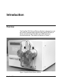
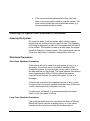
Varian Analytical Instruments
2700 Mitchell Drive
Walnut Creek, CA 94598-1675/USA
PrepStar SD-2
Solvent Delivery Module
Operation Manual
©Varian, Inc. 2001
03-914903-00:Rev. 1
Table of Contents
Introduction.............................................................................................. 1
Overview................................................................................................................... 1
Manual Organization.................................................................................................. 2
Installation................................................................................................ 3
Overview................................................................................................................... 3
Site Requirements ..................................................................................................... 3
Physical Location of the System ........................................................................... 3
Space/Weight Requirements ................................................................................ 3
Environmental Requirements................................................................................ 4
Power Requirements ............................................................................................ 4
Unpacking and Inspection.......................................................................................... 4
Preparing the Pump for Operation ............................................................................. 5
Loading the Pump Oil ........................................................................................... 5
Electrical Connections .......................................................................................... 7
Fuse Replacement................................................................................................ 7
Fluidics................................................................................................................. 7
Preliminary Test ................................................................................................... 9
Final Testing....................................................................................................... 10
System Description ............................................................................... 11
Overview................................................................................................................. 11
The Solvent Delivery System .................................................................................. 11
Materials Used in the Solvent Delivery Module ................................................... 13
Characteristics of Titanium and Stainless Steel .................................................. 13
Solvent Considerations............................................................................................ 13
Operation................................................................................................ 15
Overview................................................................................................................. 15
The Keypad and Display.......................................................................................... 15
The Display ........................................................................................................ 15
The Keypad ........................................................................................................ 17
Generating a Solvent Flow ...................................................................................... 18
Maintenance and Troubleshooting ...................................................... 19
Maintenance Overview ............................................................................................ 19
Solvent Considerations............................................................................................ 19
Cleaning the System and Shutdown Procedures...................................................... 20
PrepStar SD-2
i
Cleaning the System........................................................................................... 20
Shutdown Procedures......................................................................................... 20
Routine Maintenance............................................................................................... 21
The Pump Head ................................................................................................. 21
Replacing the Pump Seals.................................................................................. 22
Cleaning and Changing the Check Valves .......................................................... 23
Replacing the Pump Oil ...................................................................................... 25
Troubleshooting Overview ....................................................................................... 25
Troubleshooting Procedures ............................................................................... 26
Appendix ................................................................................................ 29
Specifications .......................................................................................................... 29
General Specifications........................................................................................ 29
Solvent Delivery Module Pump........................................................................... 29
Complete Spare Parts Kit ................................................................................... 29
Extended (1 year) Limited Warranty ................................................................... 29
Installation Requirements ................................................................................... 29
Physical Specifications ....................................................................................... 29
Spare Parts – PrepStar SD-2................................................................................... 30
Common Spare Parts ......................................................................................... 30
Spare Parts Kit ................................................................................................... 30
Figures
Figure 1 PrepStar Solvent Delivery Module .................................................................. 1
Figure 2 Top of pump with oil input. .............................................................................. 6
Figure 3 Rear Panel – Solvent Delivery Module............................................................ 7
Figure 4 Pumpheads .................................................................................................... 8
Figure 5 The Menu Display........................................................................................... 9
Figure 6 Design of the Solvent Delivery Module ......................................................... 12
Figure 7 Schematic of Pump Head ............................................................................. 21
Figure 8 Inlet Check Valve.......................................................................................... 24
Figure 9 Outlet Check Valve....................................................................................... 24
ii
03-914903-00:1
Introduction
Overview
The PrepStar SD-2 Solvent Delivery Module is designed to meet
the needs of scientists and engineers who require the ability to
deliver solvents at high flow rates (up to 800 mL/min) at
elevated pressures. The module is depicted in Figure 1.
Figure 1 PrepStar Solvent Delivery Module
PrepStar SD-2
1
Manual Organization
The user manual includes the following sections:
2
•
Introduction (page 1) describes the overall function of the
solvent delivery system and provides an outline of the
manual.
•
Installation (page 3) describes the required facilities and the
installation procedure.
•
System Description (Page 11) describes the characteristics
of the various components which are in contact with the
solvent.
•
Operation (page 15) describes the application program that
is used to set up and operate the system.
•
Maintenance and Troubleshooting (page 19) describes a
series of preventive maintenance operations and discusses
how you change components that need to be replaced on a
periodic basis. It also discusses a variety of problems which
you might encounter during operation of the instrument. It
includes a description of activities which should be
performed to determine the cause of problems and explains
how to repair the unit, if necessary
•
Appendix (page 29) contains the specifications and a list of
spare parts.
03-914903-00:1
Installation
Overview
The PrepStar SD-2 Solvent Delivery Module is designed to be
installed by the user. This Section describes:
•
•
the site requirements
preparing the system for use
Site Requirements
Physical Location of the System
The system should be used in a facility free from extremes of
temperature, humidity, and vibrations.
The distance between the system and the walls of the facility
must be at least 8" (20 cm). This will provide suitable ventilation
and will allow ready access in the event that any adjustments
are needed. If an island-type laboratory table is available, it
should be used, as it provides ready access to all parts of the
system.
Space/Weight Requirements
29.2 cm (W) x 19.7cm (H) x 57.5 cm (D), (11.5” x 7.75"
x 20.25") 25 kg ( 60 lb)
WARNING
PrepStar SD-2
Avoid back strain and other injuries by following all
safety precautions when lifting heavy objects.
3
Environmental Requirements
•
•
•
Temperature Range: 59 to 86 ºF (15-30 ºC)
Humidity Range: 20 to 80% Relative Humidity
Allowable temperature change: 5 ºF/hr (2.8 ºC/hr.)
Do not install near a window, a ventilation duct, or any other
device which can cause a significant change in the temperature.
Use a ventilation/exhaust line to remove solvent vapors from
the immediate vicinity of the instrument.
Power Requirements
230 Vac, 50/60 Hz, 1000 VA
A dedicated power line should be used for the system. This line
should be Electromagnetic Interference free and must be
connected to a true ground.
The system should not be connected to a power line that is
susceptible to sudden changes in power requirements (e.g., a
power line that also serves an oven or compressor). If there are
significant variations in the power line, a constant voltage
(buck/booster) transformer may be required.
Unpacking and Inspection
Place the PrepStar SD-2 on a flat surface and inspect for
damage.
Damage in transit is the responsibility of the carrier. If any
damage is found, contact the carrier and immediately. Many
carriers must receive a damage claim within 7 days of delivery,
and will need to see the shipping container.
Inspect the shipping container for indications of damage. In
North America damage occurring during transit is the
responsibility of the carrier and should be reported immediately
to the carrier and to:
4
03-914903-00:1
INSTALLATION
Varian Analytical Instruments
2700 Mitchell Drive
Walnut Creek, California 94598-1675
Attention: Customer Service
1-800-FOR-HPLC
Outside North America, please contact the carrier and your local
Varian office.
For contents of shipping container see the Standard Accessory
Kit list in the shipping box.
Carefully unpack the PrepStar SD-2 Solvent Delivery System.
It is a good idea to save the shipping container and packing
material. They provide excellent protection for the instrument in
case of future transit or storage.
If any parts are missing, please contact your sales
representative immediately.
NOTE:
If there is any apparent damage to the unit or any component, do not
plug the unit into the power line.
Preparing the Pump for Operation
Loading the Pump Oil
It is necessary to pour the oil into the gear box of the pump
before operation. This should be done as follows in Figure 2.
1. Turn the main power switch off and unplug power cord.
WARNING:
SHOCK HAZARD
PrepStar SD-2
Dangerous voltages exposed when cover is removed.
This procedure must be performed by qualified
personnel.
5
Oil fill plug
Figure 2 Top of pump with oil input.
2. Remove the screws that attach the top cover to the pump.
3. Remove the oil fill plug on the gear box.
4. Pour the contents of the bottle containing the pump oil into
the gear box (600 mL).
5. Place the VENTED cap plug into the pump (DO NOT
REPLACE THE PLUG THAT YOU REMOVED IN STEP 2).
6. Replace the top cover on the unit and replace the three
screws.
6
03-914903-00:1
INSTALLATION
Electrical Connections
The power cord is should be inserted in the power socket in the
lower left corner of the rear panel, (Figure 3).
Fuse
Compartment
Figure 3 Rear Panel – Solvent Delivery Module
Do not plug the power cords into the line voltage until all
connections have been made to all components in the
system. All power cords should be connected to a
common power line that is properly grounded.
WARNING
Fuse Replacement
Always use fuses of the correct rating and type:
5 x 20 mm, 250 Vac, 5 Amp, Type F
WARNING:
FIRE HAZARD
To avoid fire hazard replace fuses ONLY with fuse of
the same rating and type. Always switch off the AC
power and uplug the power cord before replacing a
fuse.
Fluidics
The inlet port for the Solvent Delivery Module is the manifold
that delivers solvent to the bottom of the pump. The outlet port
PrepStar SD-2
7
for the Solvent Delivery Module is the manifold connected to the
upper check valves.
Washing sections’
‘connections
Pump Outlet
Pump Inlet
Figure 4 Pumpheads
NOTE:
When connecting fittings to the system, tighten all fittings fingertight plus
a ¼ turn. Overtightening may permanently damage a fitting.
NOTE:
All inlet lines should be filtered
At the rear of each pumphead, at the top and the bottom, is a
washing section (see Figure 4 above). These connections can
be used to flush the rear of the piston seals. This is especially
useful when buffers are used as part of the mobile phase.
The washing port can be used two ways:
8
03-914903-00:1
INSTALLATION
1. A wash bottle or syringe can be used to squirt water or
methanol directly through the back of the pumphead.
This can be done individually through the two heads, or
by connecting the two heads together as shown in
Figure 4. A small pump, or a reservoir positioned above
the pump, could also be used to produce a continuous
flow of wash liquid behind the pump heads.
Preliminary Test
At this juncture, it is suggested that a preliminary test is
performed to ensure that the pump(s) deliver solvent and the
fittings do not leak.
To perform the Preliminary Test:
1. Power up the pump(s). After a few seconds, the display will
present the Menu display (Figure 5).
FL1 XXXmL PLXXXX XXXXpsi (bar)
FL2 XXXmL RAMP XXX=TXXXmn
Figure 5 The Menu Display
NOTE:
A detailed discussion of the operating program is presented in the
Operation section beginning on Page 15. The instructions listed below
are provided as a step by step protocol simply to test the system.
2. Click the Field button until the cursor is in the first character
in the FLO field. Click on the ▲key until the first character in
the FLO field is 1 (e.g. 100 mL/min). For two pump systems,
make certain that the flow is set for both pumps.
3. Click on the Field button until the cursor is on the first
character of the Press field.
If the system indicates the pressure limit in psi, click on the
▲ key until the first character in the PRESS field is 2 (e.g.
2000 psi mL/min).
If the system indicates the pressure limit in bar, move the
cursor to the second character, then click on the ▲ key until
the first character in the PRESS field is 1 (e.g. 100 bar).
PrepStar SD-2
9
4. Press the RUN button. The pump will deliver solvent at the
indicated flow rate. Allow the system to deliver solvent for
approximately five minutes and check for leaks.
5. Press the STOP button and continue the installation.
Final Testing
The final testing is done with the pressure load (e.g. HPLC
column) in place and is a high pressure test.
To perform the final test:
1. Raise the flow rate to 150 mL/min (for 200 mL/min systems)
or 600 mL/min (for 800 mL/min systems).
2. Press RUN. The system should deliver solvent at the
indicated flow rate. If the system stops due to a pressure
overload, raise the pressure limit by 500 psi (33 bar).
NOTE:
Make certain that the pressure limit is not set above the maximum
pressure indicated by manufacturer of any device that will be attached to
the solvent delivery module..
If the pressure overload is reached again, do not raise the
pressure again. Instead, the cause of the blockage should
be determined and corrected.
3. Allow the pump to deliver solvent at the indicated flow rate
for approximately 1/2 hr. and check for leaks.
10
03-914903-00:1
System Description
Overview
The PrepStar SD-2 Solvent Delivery Module system provides a
convenient method to deliver solvent at a high pressure. Two
different pumps are available, 200 mL/min and 800 mL/min.
The Solvent Delivery System
The PrepStar SD-2 Solvent Delivery Module System is
specifically designed for preparative chromatography. The pump
includes two pistons to provide ripple-free delivery of the mobile
phase. The pump is shown in Figure 6.
PrepStar SD-2
11
Figure 6 Design of the Solvent Delivery Module
Pump seals should be replaced on a periodic basis (typically
after 6 months to a year of operation). To replace pump seals,
refer to Replacing the Pump Seals, page 22.
Each check valve is fitted with 1 sapphire seat and 1 ruby ball.
These materials have been chosen for their hardness and
ensure reliable use of the pump for an extended period of time
with a minimum of maintenance. The wear and tear on the seats
and ball depend to a great extent on the amount of particulate
matter in the solvent, thus the solvent should be well filtered. If
the mobile phase is well filtered (e.g. no particulate matter), the
balls and seats should last for an extended period of time. For
information about changing seats and balls, refer to Cleaning
and Changing the Check Valves, page 23.
12
03-914903-00:1
SYSTEM DESCRIPTION
Materials Used in the Solvent Delivery Module
The following materials are used in the Solvent Delivery Module:
•
titanium, zirconia, sapphire, ruby and other ceramic
materials, PEEK and Teflon.
Characteristics of Titanium and Stainless Steel
Solvent Delivery Modules include fittings, tubing, and other
components fabricated from titanium. This material is inert to
most solvents and mobile phases.
Type 316 Stainless Steel is inert to most solvents and mobile
phases, however, the following materials should be avoided:
•
•
•
Salts containing halogens
halogenated acids at any pH
acidic solutions with a pH below 2
Solvent Considerations
Hazardous chemicals under pressure. Use proper
eye and skin protection.
The composition of the solvent used with the Solvent Delivery
Module depends on the application.
In many cases, the solvent contains an organic solvent such as
methanol or acetonitrile and a buffer (e.g. 0.05 M
KH2PO4/H3PO4, pH = 4.0).
To maximize the efficiency and reliability of the instrument, the
following general guidelines for the solvent should be heeded.
PrepStar SD-2
•
Water should be purified using a reverse osmosis system.
•
High quality organic solvents should be used.
•
Mobile phases should be filtered through a 0.22 µ
membrane filter before use to remove any particulate
13
matter. Filters should be checked to ensure that extractable
materials are not present.
•
If you use a buffer solution, ensure that fresh solutions are
used. Microbiological growth can occur in a few days, this
may change the composition of the buffer and/or lead to
particulate matter in the system.
NOTE:
Do not leave water, buffers, salts, or other potentially corrosive materials
in the system when it is not in use. Failure to flush these material from
the liquid path may result in damage to the system and could possibly
void the warranty. It is very important to be aware of materials which are
potentially corrosive to the system.
NOTE:
If caked salt is observed on any part of the system (e.g. by a fitting),
clean it up and determine the cause of the leak before continuing.
14
03-914903-00:1
Operation
Overview
The PrepStar SD-2 Solvent Delivery Module is controlled via the
controller on the front panel.
In this section, we describe the general mode of operation of the
system via the controller on the Solvent Delivery Module and
provide a definition of each control.
The Keypad and Display
The keypad and the display provide control of the instrument
when it is in manual mode. All user entry is performed via the
keypad as described below.
The Display
The display has two lines which present the system status and
allows for entry of the desired operating information as follows:
•
FLO is used to indicate the desired flow rate(s). The
maximum value is 800.0 mL/min. The flow rate that will
be delivered when the RUN button is pressed is
dependent on the RAMP entry.
•
If a constant flow rate is desired, enter the flow in the
first flow field and a RAMP of zero. When the RUN button
is pressed, the pump will deliver the indicated flow rate
until the STOP button is pressed.
If the flow rate should change during the run, enter the
initial flow rate in the first flow field (FL1) and the final
PrepStar SD-2
15
flow rate in the second flow field, (FL2). When the RUN
button is pressed, the pump will deliver the indicated
flow rate until the STOP button is pressed. The flow rate
at a given instant is determined by the starting flow rate,
the final flow rate and the ramp time. As an example, if
you select a ramp of 200 minutes and a starting flow
rate of 200 mL/min and a final flow rate of 100 mL/min,
the flow will be 150 mL/min after 100 minutes. At the
end of the ramp period, the flow rate will remain at the
final flow value setting until the STOP button is pressed.
•
RAMP is used to indicate the desired time for the change
in the flow indicated above (in min). When the RUN
button is pressed, the flow rate will increase from the
start flow rate to the final flow rate in a linear manner at
the indicated rate until the flow rate is equal to the upper
flow rate indicated above. At that point (=), the mobile
phase will continue to be delivered at the flow rate
indicated in the second FLO field until the STOP button is
pressed.
•
TIME (T) indicates the period of time that has elapsed in
the current operation (i.e., since the RUN button or the
RESET button was pressed). This is not editable by the
user.
•
PL indicates the user selected pressure limit for the
system. The maximum values are indicated in Table 1.
The right field is the actual pressure during a run.
Table 1 Maximum Pressure
Psi
Bar
16
2500
170
03-914903-00:1
OPERATION
The Keypad
The keypad includes the following keys:
•
FIELD: Moves the cursor to the next position.
•
▲: Increases the value of the active character. This is a two
speed control, if you click for a short period, the value
increases by one character; if you hold the button down, the
value will increase on a continuous basis.
•
▼: Decreases the value of the active character. This is a
two speed control, if you click for a short period, the value
decreases by one character; if you hold the button down, the
value will decrease on a continuous basis.
•
RUN: Initiates the delivery of the mobile phase at the
indicated flow rate. If a RAMP has been selected, the flow
rate will start at the value indicated in the first flow field and
increase (decrease) until the flow rate indicated by the
second flow rate field. The time for the change in set in the
RAMP field.
If a flow rate ramp has been halted due to STOP command,
the flow rate ramp will continue when the RUN button is
pressed.
PrepStar SD-2
•
STOP: Terminates the delivery of the solvent and the RUN
Time clock. If a flow rate ramp is active, the ramp will be
held at the present point and will resume when the RUN
button is pressed.
•
RESET: If a flow ramp has been selected, this button is used
to set the flow rate that will be delivered when the RUN
button is pressed to the initial flow rate. This button is only
active after the STOP button has been pressed; if the button
is not pressed, the ramp will continue.
17
Generating a Solvent Flow
To generate a solvent flow:
1. Enter the desired flow rate
2. Enter the maximum pressure
3. Enter the ramp (if desired)
4. Press RUN.
18
03-914903-00:1
Maintenance and Troubleshooting
Maintenance Overview
On a routine basis, the following activities are recommended to
maintain the system in maximum operating condition:
•
always use high purity solvent and ensure that particulate
matter does not enter the system.
•
keep the system clean and follow a shutdown protocol.
•
replace consumable items on a periodic basis.
When a system is first installed, it may be wise to obtain
performance data from an application that can be readily
obtained on a consistent basis. This application can be used as
a benchmark to monitor the performance of the system.
Lists of recommended spare parts are presented in the
Appendix.
Solvent Considerations
The use of high purity solvents will maximize performance and
minimize problems with the system. Water should be purified
using a reverse osmosis system and high quality organic
solvents should be used.
It is important to keep particulate matter out of the system. The
following steps are recommended:
•
PrepStar SD-2
Solvents should be filtered through a 0.22 µm
membrane filter before use to remove any particulate
matter. Filters should be checked to ensure that
extractable materials are not present.
19
•
If the solvent includes salts and/or buffers, the flush
ports on the pump can be used to rinse the system. The
rinse solution should be free of particulate matter (e.g.
de-ionized water should be used).
Cleaning the System and Shutdown Procedures
Cleaning the System
On a periodic basis, flush the system with a volatile organic
solvent such as methanol using a rapid flow rate. The frequency
of flushing is dependent on the use of the system and the nature
of the solvent. If the system is used on a daily basis, the system
should be flushed on a weekly basis. If the instrument is used on
a less than daily basis, it should be flushed after each use.
Shutdown Procedures
Short-Term Shutdown Procedures
If the system will not be used for a short period of time (e.g. a
few hours), the solvent can be recycled to maintain a flow
through the system. A lower flow rate can be used to minimize
the wear and tear on the pumps. The upper pressure limit should
be set approximately 500 psi (35 bar) above the pressure
required for the flow rate (to protect the system in case of a
blockage).
If the solvent is recycled for a significant period of time, do not
use this solvent for normal operation because some of the more
volatile components may evaporate over time.
For short term shutdowns, it is recommended that the power
switch on the front panel is left on.
Long-Term Shutdown Procedures
The conditions below are to be used when the Solvent Delivery
Module will not be used for a lengthy period, or if you cannot
maintain the flow of solvent during the shutdown period.
20
03-914903-00:1
MAINTENANCE AND TROUBLESHOOTING
To prepare the system for shutdown:
1) Flush with water until all salts and buffers are removed.
2) Flush with methanol so that the water is removed.
Routine Maintenance
The Pump Head
Under normal operating conditions, it will be necessary to
replace some components (e.g., the pump seals and check
valves). The frequency of replacement is dependent on a variety
of factors including the nature of the solvent, the number of
hours/day that the system is used, the efficacy of removal of
particulate matter from the solvent, and the pressure that the
pump is required to deliver. As a rough rule of thumb, pump
seals should be replaced every 6-12 months, and check valves
should be replaced after a few years (or sooner depending on
the usage and the solvent).
A
B
D
E F
G
H
C
A
B
C
D
E
F
G
I
J
K
L
M
N
O
Figure 7 Schematic of Pump Head
Outlet
Pumphead (high pressure segment)
Inlet
Spring Seal
O-Ring
PEEK Back up Ring
Rulon Guide
PrepStar SD-2
Legend
H
I
J
K
L
M
N
O
Pumphead (low pressure segment)
O-Ring
Wash Spring
Spring Seal
Rulon Guide
Retainer Plate
Screws
Plunger
21
Replacing the Pump Seals
The pump seals should be replaced when leaks are observed
from the pump. Both seals should be replaced at the same time.
To replace the pump seals:
1. Remove all inlet and outlet tubing.
2. Remove all tubing for the wash ports (if present).
3. Unscrew the two screws which hold the pump head to the
system.
CAUTION
Be sure to support the pump head while unscrewing the
bolts.
4. Carefully remove the low pressure segment of the pump
head from the system by sliding it off the plunger.
NOTE:
Pull the pump head directly toward you. If significant pressure is placed
on the plunger while the pump head is being removed, the plunger could
be broken.
5. Remove and replace the seals from inside the pump head
(both seals should be replaced).
NOTE:
When you are removing the seals, take care not to scratch other
components of the pump.
6. Use a spare plunger to ensure proper alignment of the
components after they are put into the head.
NOTE:
When installing the seals, ensure that the springs are facing the pump
head. Take care to ensure that the seals are not distorted, bent or
dented.
7. Place the plunger into the pump head and press on the cap
until it is flush with pump head.
8. Remove the spare plunger and carefully slide the
refurbished pump head on to the plunger on the pump.
22
03-914903-00:1
MAINTENANCE AND TROUBLESHOOTING
NOTE:
Inspect the plunger before reinstalling the pump head to ensure that it is
not damaged.
9. Replace the two screws.
10. Replace all tubing.
11. Pump acetone through the pump for 10-15 minutes at a rate
of 100 mL/min. Acetone serves to swell the pump seals and
provide a tighter fit. The acetone can be recycled for this
operation.
Cleaning and Changing the Check Valves
Each pump head is equipped with an inlet and an outlet check
valve. Both valves should be cleaned (changed) at the same
time. The check valve has a ball and seat design and includes a
ruby ball with sapphire seat in a titanium housing.
The best way to determine if the check valves have deteriorated
is to monitor the flow rate at a set of specific conditions. For
systems that are dedicated to a specific application, the flow rate
should be checked on a routine basis (e.g., on a monthly basis).
If the system is used under varying conditions, a standard set of
conditions should be developed for this test. When a defective
check valve is found (i.e., the observed flow rate is incorrect), it
should be cleaned or replaced as described below.
To clean the check valves:
1. Remove appropriate plumbing from the check valve
connector (take care not to put undue stress on the
manifolds).
2. Remove the check valve connector (with a 13 mm or ½"
wrench).
3. Rinse the interior of the check valve assembly using an
appropriate solvent (an organic solvent such as methanol or
acetonitrile will remove most materials).
4. When the rinse solvent is clear, replace the check valve
assembly.
PrepStar SD-2
23
To replace the check valves:
1. Remove appropriate plumbing from the check valve
connector (take care not to put undue stress on the
manifolds).
2. Remove the check valve connector (with a 25 mm or 1"
wrench).
3. Carefully remove the check valve housing. (The entire
housing should be removed.)
4. If necessary, force the check valve out of its housing by
using a rod inserted from the tube end.
5. Take the check valve apart. The sapphire seats and ruby
ball should be discarded.
6. Install new seats and ruby ball and reassemble the check
valve. When reassembling the check valve, ensure that the
ruby ball is seated against the shiny part of the seat.
NOTE:
The inlet check valve and outlet check valve are put together in a
different order. Refer to Figure 8 (inlet check valve) and Figure 9 (outlet
check valve) for assistance.
A
CD
B
E
F
Figure 8 Inlet Check Valve
F
A
E
DC
B
Figure 9 Outlet Check Valve
A Housing
B PEEK Seal
C Sapphire Seat
24
Legend
D
E
F
Ruby Ball
Cage
PEEK Spacer
03-914903-00:1
MAINTENANCE AND TROUBLESHOOTING
1. Place the check valve into its housing and then into the
pump head. Tighten the connector. The check valves should
be snug (finger tight plus ¼ turn with a wrench). DO NOT
OVERTIGHTEN the fittings as this may cause damage to
the internal components.
2. Replace the inlet tubing.
3. Prime the pump. It may be necessary to force solvent into
the pump head using a squeeze bottle.
4. Replace outlet tubing.
Replacing the Pump Oil
The pump oil should be replaced every year or after 2000 hours
of operation, whichever comes first. Meropa 150 (Texaco) oil
should be used.
Troubleshooting Overview
Troubleshooting is defined as the determination of the reason
for an abnormal response from the system. Troubleshooting can
be simplified and the amount of downtime can be reduced by a
consideration of the following guidelines:
PrepStar SD-2
•
In almost all situations, there is one proximate cause for
the problem
•
A fundamental knowledge of the role of each
component in the system is extremely useful in
diagnosis of the problem.
•
The availability of critical spare parts is extremely
useful. If it is suspected that a part is faulty, replacing
that part may rapidly solve the problem.
•
If any aspect of the operating conditions are changed,
run a “before” operation and an “after” operation to
ensure that the effect of the change is well understood.
Do not consider any change as trivial.
25
•
If you change the supplier of organic solvents, buffers,
salts, etc., ensure that the new and old reagents are
equivalent by running the same operation with each.
In normal operation, the Solvent Delivery Module is quiet. If a
change in the volume or the tone from the system is observed,
determine the cause of the noise. Although this is an unscientific
approach, a change in the volume and/or tone is frequently a
good indication that something has changed.
A service department, which is designed to assist in the
diagnosing and repair of any problems that may occur, is
available. If you need assistance, please contact your nearest
sales or service representative.
Additional troubleshooting information is contained in manuals
provided with components such as the variable wavelength
detector, the recorder, etc.
Troubleshooting Procedures
A Component does not Operate
If a component does not start, the initial response should be to
ensure that the component is connected to the power line and
the fuse is good. It may be worthwhile to turn the component off
and on again.
Problem
Probable Cause
Solution
Pump will not start
Pump is not plugged in
Plug pump in
Circuit breaker off
Turn circuit breaker on
Fuse is blown in pump
Check/replace fuse
Drive not reset on power up
Reset drive by turning
power off, wait 30 seconds
and turn power on
Pump will not start
26
03-914903-00:1
MAINTENANCE AND TROUBLESHOOTING
Fluidics Problems
Problem
Probable Cause
Solution
Abnormally High Pressure
Tubing clogged
Isolate clogged line. Flush
out at high flow rate.
Low flow rate
(No Pressure)
Pumps not primed
Disconnect application and
run at high flow rate
Loose inlet lines
Low flow rate
(Under Pressure)
Liquid leaking from
back of pump heads
Significant pressure
variance over a
short time period
(spikes)
PrepStar SD-2
Loose fittings between
pump and system
Tighten fittings on inlet
pump lines.
Check valves
Clean or replace valves
(Page 23)
High pressure seal
deteriorated
Replace seal
(Page 22)
Check valves not
operating efficiently
Clean or replace valves
(Page 23)
Back seal
deteriorated
Replace Seal
(Page 22)
Degas solvent if a
persistent problem
27
28
03-914903-00:1
Appendix
Specifications
General Specifications
•
Compact, modular, benchtop design
•
Maximum operating pressure 800 - 2500 psi (165 bar).
Solvent Delivery Module Pump
•
Includes all general specifications listed above
•
Duplex zirconia plunger pump
•
Titanium pump heads
•
Flow Rate: SD-2 80 to 800 mL/min (upper flow rate limit is dependent on
solvent viscosity)
•
Pressure monitor (displayed on control panel)
Complete Spare Parts Kit
Extended (1 year) Limited Warranty
Installation Requirements
•
Power: 230 Vac, 50/60 Hz, 1000 VA
Physical Specifications
•
•
Solvent Delivery Module: 11.5" W x 7.75 H x 20.25"D (29.2 cm x 19.7 cm x 57.5
cm)
Weight: approximately 60 lb (27 kg).
PrepStar SD-2
29
Spare Parts – PrepStar SD-2
Common Spare Parts
Item
Part Number
PE/Zinc Chromate (White) Seals
Viton O-Rings
Check Valve Cartridge
Nut (1/8"), Stainless Steel
Ferrule (1/8"), LITE-TOUCH
Luer Lock Adapter
Zirconia Plunger, 10 mm
Ferrule (1/4"), Titanium
Nut (1/4"), Stainless Steel
Tee (1/8"), Titanium
Inverted Nut (1/4"), Stainless Steel
Fuse Kit (220V)
Ferrule, (1/8"), PEEK
PCG601660010
PCG60130088100
PCG549A00005T
PCG369220200
PCG369000200LT
PCG369520100
PCG6030F3026771
PCG369000400Ti
PCG369220400
PCG3632T0400V
PCG362720400V
PCG50220STKIT
PCG3690P0200
Quantity
(in spare parts kit *)
16
16
6
8
8
5
1
8
8
1
4
1
4
Spare Parts Kit
The PrepStar SD-2 Spare Parts Kit (02-KIT-ReS800) includes
the above items.
Please call Varian for price and delivery information.
30
03-914903-00:1