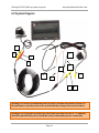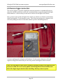
1
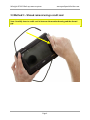
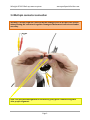
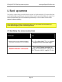
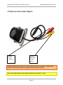
SAFESIGHT ™ SC9003
Reverse back up camera system
Installation Guide and
User’s Manual
Version 1
Table of Contents
1. Introduction...................................................................................................................................................................................................1
1.1 Notes and Warnings .......................................................................................................................................................................1
2. Installation/Setup .......................................................................................................................................................................................2
2.1 LCD monitor shroud removal.....................................................................................................................................................2
2.2 Method 1 – Shroud removal using a screwdriver .............................................................................................................3
2.3 Method 2 – Shroud removal using a credit card ................................................................................................................4
2.4 Method 2 – Shroud Mounting tabs and receiver................................................................................................................5
3. Monitor Wiring harness ...........................................................................................................................................................................6
3.1 Identifying the bare wires............................................................................................................................................................6
3.2 Method Identifying the RCA cables..........................................................................................................................................7
3.3 Monitor cable diagram ..................................................................................................................................................................8
3.4 Multi-pin connector connection ................................................................................................................................................9
4. Back up camera .........................................................................................................................................................................................10
4.1 Identifying the camera connections .....................................................................................................................................10
4.2 Back up camera cable diagram ...............................................................................................................................................11
5. Camera extension cable.........................................................................................................................................................................12
5.1 Identifying the camera extension cable connections....................................................................................................12
5.2 Back up Camera Cable Diagram..............................................................................................................................................13
6. System connections ..........................................................................................................................................................................14-15
6.1 Cable connections ..................................................................................................................................................................14-15
6.2 System Diagram.............................................................................................................................................................................16
6.3 In-line fuse connection ...............................................................................................................................................................17
6.4 Main power connection.......................................................................................................................................................18-19
6.5 Reverse trigger connection ...............................................................................................................................................20-21
7. Troubleshooting........................................................................................................................................................................................22
7.1 Unit will not turn on when the vehicle is placed in reverse.......................................................................................23
7.2 Monitor turns on but camera does not when placed in reverse..............................................................................22
7.3 Monitor and camera will not turn on after the vehicle is taken out of reverse.................................................23
7.4 Monitor randomly turns on and off. .....................................................................................................................................23
Safesight SC9003 Back up camera system
www.qualitymobilevideo.com
1. Introduction
Thank you for purchasing the Safesight SC9003 Reverse camera system! This system will
help prevent the most deadly type of automobile accidents, reversing accidents. All that’s
left is to install and use your system. In the following information we will guide you
through installing your system and getting the most out of it.
First we begin with a couple of things you should have on hand to help with the installation
of your system:
•
•
•
•
•
•
Voltmeter or DMM
Basic hand tools, i.e. (pliers, screwdriver, socket set)
Electrical tape
Wire ties
Crimp connectors
Wire crimper
1.1 Notes and Warnings
Here we show you how we will outline different things that will help and point things out
during the course of your installation and use. (as shown below).
Note: Notes will be highlighted in this yellow box.
Warning: Warnings will be highlighted in this orange box.
Page 1
Safesight SC9003 Back up camera system
www.qualitymobilevideo.com
2. Installation/Setup
We begin by identifying the contents of the back up camera system:
1.
2.
3.
4.
5.
6.
7.
8.
LCD Monitor
Back up camera
Monitor wiring harness
Camera wiring harness
Extension cable
Remote Control
Mounting stand
Headrest shroud
Warning: All electrical connections should be done after removing the negative post
of the battery. Under no circumstance does qualitymobilevideo.com assume any
liability. Use these instructions at your own risk. These instructions are meant as a
guide but require knowledge by the installer. If you are unfamiliar please seek
professional advice prior to any and all installation.
2.1 LCD monitor shroud removal
When un-packaging the monitor you will typically find the monitor already inserted into
the headrest shroud. Here is how to remove the monitor from its shroud. The monitor is
held into the shroud with two tabs on the left and right side of the monitor and shroud.
To remove the monitor from the shroud you will need to carefully pry the tab with a small
flat head screw driver or pick.
Warning: these tabs can break very easily if pried too far.
Page 2
Safesight SC9003 Back up camera system
www.qualitymobilevideo.com
2.2 Method 1: - Shroud removal using a screwdriver
See the picture below for added clarification on the removal of the monitor from its shroud.
Note: Carefully insert the screwdriver or pick and gently pry the tab back.
If the shroud is installed and you cannot access the tabs or you fear breaking the tab there
is another method to remove the monitor from its shroud. See method 2 on the next page.
Page 3
Safesight SC9003 Back up camera system
www.qualitymobilevideo.com
2.3 Method 2: - Shroud removal using a credit card
Note: Carefully insert a credit card in between the monitor housing and the shroud
gap
Page 4
Safesight SC9003 Back up camera system
www.qualitymobilevideo.com
2.4 Shroud mounting tabs and
receivers
Note: The rectangular slot and tab lock into one another
Page 5
Safesight SC9003 Back up camera system
www.qualitymobilevideo.com
3. Monitor wiring harness
The monitor wiring harness is a single harness that has a multi-pin connector on one end
and a series of wires and RCA cables on the other. The black box contains a power filter and
fuse that prevents damage in the event of a short circuit. The multi-pin connector has a tab
that prevents the connectors from being inserted incorrectly to one another.
Note: In the event that the monitor will not respond please check to make sure the
fuse is seated properly and fuse is not blown.
3.1 Identifying the bare wires
Bare Wire color
Connection
Red
Positive + 12 volts – connect this to a
switched power supply at the fuse box so
that the monitor will get power only when
the key is on.
Black
Negative – 12 volts – connect this to the
ground of the vehicle.
Green
Positive + 12 volt trigger – when 12 volts is
applied to this wire it will trigger the
monitor to turn on to the camera input, this
will prevent you from turning the monitor
off until 12 volts is removed from this wire.
Page 6
Safesight SC9003 Back up camera system
www.qualitymobilevideo.com
3.2 Identifying the RCA cables
RCA Cable
Connection
Male RCA Cable
Connect this to a secondary camera or
DVD source. This input is not trigger-able
and can only be used if 12 volts is not
applied to the green trigger wire.
Female RCA Cable
Connect this to the back up camera or to a
source that you want to display when 12
volts is applied to the green trigger wire.
Page 7
Safesight SC9003 Back up camera system
www.qualitymobilevideo.com
3.3 Monitor cable diagram
Multi-pin
connector
Male RCA
Cable
Female RCA
Cable
Red bare wire
Page 8
Black bare
wire
Green
bare wire
Safesight SC9003 Back up camera system
www.qualitymobilevideo.com
3.4 Multi-pin connector connection
Warning: Carefully align the cables so that no damage occurs to the pins, use caution
when pressing the connector’s together. Damage to the harness is not covered under
warranty.
Note: Tab prevents misalignment of connectors, gently press connectors together
after proper alignment.
Page 9
Safesight SC9003 Back up camera system
www.qualitymobilevideo.com
4. Back up camera
The back up camera that is included in this system is a high sensitivity CCD camera that has
excellent low light capabilities. In situations where there is no ambient light the camera has
infrared illumination that will illuminate approximately a 10 foot radius in front of the
camera for better visibility.
Note: Infrared LED’s that are inside the camera are not visible to the human eye.
These will not light up, this is normal operation.
4.1 Identifying the camera connections
Connector
Use
Yellow Female RCA Cable
This is the video output. This is a standard
composite NTSC RCA video output.
Red DC Power connector
This is the DC power connector; the
center pin of the connector is positive 12
volts. The outer shield is negative 12 volts.
Page 10
Safesight SC9003 Back up camera system
www.qualitymobilevideo.com
4.2 Back up camera cable diagram
Red DC
Power
connector
Yellow
RCA video
output
cable
Warning: Make sure to make DC Power connection when no power is applied and
battery is disconnected, short is possible if not inserted correctly.
Note: Center pin on the Red DC power connector is positive 12 volts
Page 11
Safesight SC9003 Back up camera system
www.qualitymobilevideo.com
5. Camera extension cable
The extension cable that is included with this kit is a shielded 60 foot cable that carries
composite video and 12 Volts DC power and ground. The cable has two ends, one end has
two connectors and the other end has one RCA connector and two bare leads.
5.1 Identifying the Camera Extension cable connections
Connector
Use
Yellow male RCA Cable
This is a straight through video cable,
when connected to the camera it will carry
the video signal to the monitor.
Red DC Power connector
This is the DC power connector; the
center pin of the connector is positive 12
volts. The outer shield is negative 12 volts.
Red bare wire
This is the 12 volt positive power
connection for the camera.
Black bare wire
This is the 12 volt negative power
connection for the camera.
Page 12
Safesight SC9003 Back up camera system
www.qualitymobilevideo.com
5.2 Back up Camera Cable Diagram
Red bare
wire
Black bare
wire
RCA
connector
Page 13
Red DC
power
connector
Safesight SC9003 Back up camera system
www.qualitymobilevideo.com
6. System connections
There are several ways to install this system. We will only discuss the way we recommend
installing the system so that it can be used in many different ways. You will be able to turn
the system on at any time and the system will automatically turn on when the vehicle is
placed in reverse.
6.1 Cable connections
Key
Location
Connector
Use
1.
Camera
Yellow female RCA Cable
This connects to the yellow
RCA cable on the extension
cable.
2.
Camera
Red DC Power connector
This connects to the Red DC
power connector on the
extension cable.
3.
Extension cable
Red DC Power connector
Connects to the Red DC power
connector #2.
4.
Extension cable
Yellow male RCA Cable
Connects to the yellow female
RCA cable #1.
Red bare wire
This is the 12 volt positive
power connection for the
camera. This will connect to
the same location you get
power from.
5.
Extension cable
Page 14
Safesight SC9003 Back up camera system
www.qualitymobilevideo.com
6.
Extension cable
Black bare wire
This is the 12 volt negative
power connection for the
camera. This will connect to
the same location you get
power from.
7.
Extension cable
Yellow male RCA Cable
Connects to the yellow female
RCA cable #8.
8.
Monitor harness
Yellow female RCA Cable
Connects to the yellow male
RCA cable #7.
Yellow male RCA Cable
This can be left unplugged.
nd
This is the 2 video input for
another camera or other
source.
Red
Positive + 12 volts – connect
this to the fuse box or other
positive circuit of the vehicle
that switches on with the key.
This connects to the same
location as #5
Black
Negative – 12 volts – connect
this to the ground of the
vehicle. This connects to the
same location as #6
Green
Positive + 12 volt trigger – this
connects to the positive side of
the reverse light. This triggers
the monitor to turn on in
reverse.
9.
10.
11.
12.
Monitor harness
Monitor harness
Monitor harness
Monitor harness
Note: The extension cable can only be used one way, make sure when running cable
in the vehicle you place the end with two connectors at the camera.
Page 15
Safesight SC9003 Back up camera system
www.qualitymobilevideo.com
6.2 System Diagram
1
4
11
2
3
12
6
10
9
5
7
8
Warning: It is always recommended that you place an inline fuse within 6 inches of
the main power tap; this protects the system and the wiring in the event of a short.
Warning: Fire is possible if inline fuse is not used and a short occurs. A 7.5 amp fuse
should be placed inline prior to both the camera and monitor power connection.
Page 16
Safesight SC9003 Back up camera system
www.qualitymobilevideo.com
6.3 In-line fuse connection (not included)
An inline fuse is recommended to be put in place within 6 inches of the power tap. In-line
fuses prevent fires and damage to equipment in the event of a short circuit. In-line fuses
and fuse holders can be purchased at any automobile store or electronics
store.
To power supply of
fuse block
Fuse 7.5 amp
Monitor power lead
Camera power lead
Page 17
Safesight SC9003 Back up camera system
www.qualitymobilevideo.com
6.4 Main power connection
The main power connection can be made many different ways. You can connect main
power by:
• Using a cigarette lighter cord
• Taping the back of a cigarette lighter
• Tapping power at the fuse block
• Tapping power from an auxiliary circuit
• Tapping power from the key cylinder
The method we recommend is to connect power to the fuse block. We recommend using a
voltmeter to find a fuse or circuit that turns on with the key and is not a critical circuit like
“ABS pump”. You typically want to tap circuits like radio, cigarette lighter, auxiliary power
socket. In the event of a short circuit you will not lose a critical component that could
compromise safety.
The easiest way to tap the fuse block is to purchase a fuse tap from us or any major auto
parts store. The fuse tap will supply you with a terminal or wire in which you will connect
to your fuse.
At the fuse block you make your positive power connection for both the monitor and
camera.
The negative power connection can be made anywhere on the vehicle. We recommend that
you place the ground on a factory ground terminal.
Page 18
Safesight SC9003 Back up camera system
www.qualitymobilevideo.com
In-line fuse to protect in the
event of a short
Fuse tap
Warning: It is always recommended that you place an inline fuse within 6 inches of
the main power tap; this protects the system and the wiring in the event of a short.
Warning: Fire is possible if inline fuse is not used and a short occurs. A 7.5 amp fuse
should be placed in line prior to both the camera and monitor power connection.
Page 19
Safesight SC9003 Back up camera system
www.qualitymobilevideo.com
6.5 Reverse trigger connection
The reverse trigger is a positive signal that causes the monitor to automatically turn on
when the vehicle is placed in reverse. We recommend that you tap this signal at the light
bulb connector. To access this you will need to remove the tail light of the vehicle.
Once you have removed the tail light of the vehicle you will use a voltmeter to determine
which lead supplies 12 volts positive power. This is done by setting your voltmeter to dc
volts and probing the wires to determine which is positive and what ground is.
A correct reading on the voltmeter will indicate +12 volts; some voltmeters will read
negative voltage, this means that you have the positive and negative wires reversed.
Note: This step must be done with a voltmeter; guessing or using a test light will yield
incorrect results. We receive many phone calls stating defective merchandise and
this is the single largest mistake when installing a back up camera system.
Page 20
Safesight SC9003 Back up camera system
www.qualitymobilevideo.com
Once you determine which wire is the positive signal you will tap this circuit with a wire
tap. You will need to connect this to the green lead of the monitor.
Connect reverse
trigger to this
lead
Page 21
Safesight SC9003 Back up camera system
www.qualitymobilevideo.com
7. Troubleshooting
This section of the guide should highlight common issues users may encounter and offer
simple solutions.
7.1 Unit will not turn on when the vehicle is placed in reverse
Monitor will not power on when the vehicle is placed in reverse. This problem usually
stems from an incorrect wire being tapped for the reverse signal. We recommend using a
volt meter to determine what wire the correct one to tap. Avoid using a test light as this can
give you false confirmations of circuits.
Determine the correct circuit to tap using a volt meter.
Meter must read 12 volts when the vehicle is placed into reverse.
Tap this wire using a wire tap.
Ensure that the trigger wire that runs the length of the vehicle to the monitor has
not been damaged or shorted.
5. If steps 1 -4 do not rectify the situation we recommend removing the system and
connect the system directly to the vehicles battery to test. Connect both red wires to
the positive side of the battery; connect both black wires to the negative side of the
battery. To test the operation, connect the green wire to the positive side of the
battery. If normal operation resumes, you have made an error in installation with
regards to the reverse wire. Please re-read section 6.5.
1.
2.
3.
4.
7.2 Monitor turns on but camera does not when placed in reverse
Monitor will power up but the monitor shows no image. This is typically caused by poor
power connection or incorrect connection for power on the camera. We recommend that
you tap power for the camera in the same location that you tap power for the monitor. This
ensures that the camera will have power anytime the monitor has power and can be used
at anytime, by manually turning the monitor on.
1. Ensure that power connection for the camera was tapped at the same location as the
monitor.
2. Ensure that camera cable has not been damaged or pinched.
3. Ensure that camera RCA cable is connected to the proper video input.
4. Test the connections of the camera and monitor to ensure 12 volts is at the
terminals when the system is on.
5. Check the fuse that was placed in line to protect the wiring, it should not be blown.
Page 22
Safesight SC9003 Back up camera system
www.qualitymobilevideo.com
7.3 Monitor and camera will not turn on after the vehicle is taken
out of reverse.
The system should turn on and off manually when the vehicle is running if you have
connected the system as we described in this manual.
•
•
•
Check monitor power connection to ensure that the red wire has positive 12 volts
anytime the vehicle is running or the key is turned to position 2.
Check monitor power connection to ensure that the red DC power connector has
positive 12 volts on the center pin and negative 12 volts on the outer shield anytime
the vehicle is running or the key is turned to position 2.
Check the inline fuse, it should not be blown.
7.4 Monitor randomly turns on and off.
The monitor will randomly turn on or off if the incorrect reverse circuit is used. Many
newer vehicles have light bulbs that have dual filaments. Dual filament bulbs typically have
a three wire connection.
1. Use a voltmeter to determine which wire is the correct one to tap.
2. Meter must read 12 volts when the vehicle is placed into reverse. Any fluctuation
in voltage larger than one volt generally means that this incorrect wire has been
tapped.
3. Tap the reverse wire using a insulated wire tap.
4. Ensure that the trigger wire that runs the length of the vehicle to the monitor has
not been damaged or shorted.
Page 23