1
MicroEJ®: STM32F429I-DISCO: Develop a Java Application [Getting Started]
6 Appendix
6.1 STM32F429I-DISCO Technical Specifications
The following table illustrates some board features used by the Java platform. It doesn't list all board
features (such as all available memories on the board).
MCU architecture
Cortex-M4 (STM32F429ZIT6)
MCU Clock speed
180MHz (225 DMIPS)
Internal Flash
2 MBytes
Internal RAM
128 KBytes
External RAM
8 MBytes (SDRAM)
Table 6.1. STM32F429I-DISCO Technical Specifications
6.2 Platform Configuration
6.2.1 Trace Port
All traces (System.out.print) and debug traces (Java exceptions) out on USART 2. The TX (RX is
useless) of this USART is available on the P1 connector: PD5. On the computer, connect a serial sniffer:
115200 bauds, 8 bits of data, 1 stop bit, no parity.
6.2.2 ECOM Comm Ports
The ECOM Comm implementation manages one Comm port. The RX and TX pins are available on the
P1 connector, respectively PA10 and PA9.
6.2.3 MicroUI Input Events
The hardware switch (USER) sends the event Command ESC to MicroUI library.
6.2.4 MicroUI LEDs
MicroUI uses the IDs 0 and 1 to target the LEDs, respectively the green and red LEDs.
6.3 Board Setup
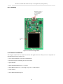
This section explains how to configure and connect the STM32F429I-DISCO board.
6.3.1 Jumpers and Switches
Set all jumpers and switches to their default settings: please refer to the STM32F429I-DISCO documentation (STMicroelectronics documentation: User manual STM32F429I-DISCO kit board).
6.3.2 Power Supply
Select your power supply mode: please refer to the STM32F429I-DISCO documentation (STMicroelectronics documentation: UM1662 User manual STM32F429I-DISCO kit board).
14