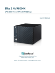
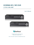
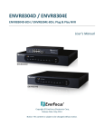
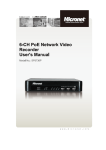
Download EPHD16+U Universal DVR
Transcript
EPHD16+U 16CH, 1080p, Real-time, Universal DVR User’s Manual Copyright © EverFocus Electronics Corp, Release Date: July, 2014 Notice: This content is subject to be changed without notice. EVERFOCUS ELECTRONICS CORPORATION EPHD16+U Universal DVR User’s Manual 2014 EverFocus Electronics Corp www.everfocus.com All rights reserved. No part of the contents of this manual may be reproduced or transmitted in any form or by any means without written permission of the Everfocus Electronics Corporation. Release Date: July, 2014 QuickTime is a registered trademark of the Apple Computer, Inc. Windows is a registered trademark of the Microsoft Corporation. Linksys is a registered trademark of the Linksys Corporation. D-Link is a registered trademark of the D-Link Corporation. DynDNS is a registered trademark of the DynDNS.org Corporation. Other product and company names mentioned herein may be the trademarks of their respective owners. Safety Precautions Refer all work related to the installation of this product to qualified service personnel or system installers. Do not block the ventilation openings or slots on the cover. Do not drop metallic parts through slots. This could permanently damage the appliance. Turn the power off immediately and contact qualified service personnel for service. Do not attempt to disassemble the appliance. To prevent electric shock, do not remove screws or covers. There are no user-serviceable parts inside. Contact qualified service personnel for maintenance. Handle the appliance with care. Do not strike or shake, as this may damage the appliance. Do not expose the appliance to water or moisture, nor try to operate it in wet areas. Do take immediate action if the appliance becomes wet. Turn the power off and refer servicing to qualified service personnel. Moisture may damage the appliance and also may cause electric shock. Do not use strong or abrasive detergents when cleaning the appliance body. Use a dry cloth to clean the appliance when it is dirty. When the dirt is hard to remove, use a mild detergent and wipe gently. Do not overload outlets and extension cords as this may result in a risk of fire or electric shock. Do not operate the appliance beyond its specified temperature, humidity or power source ratings. Do not use the appliance in an extreme environment where high temperature or high humidity exists. Use the DVR at temperatures within 0°C~40°C / 32°F~104°F (Storage). The input power source is 100-240 VAC~. Read Instructions All the safety and operating instructions should be read before the unit is operated. Retain Instructions The safety and operating instructions should be retained for future reference. Heed Warnings All warnings on the unit and in the operating instructions should be adhered to. ii Follow Instructions All operating and use instructions should be followed. Cleaning Unplug the unit from the outlet before cleaning. Do not use liquid cleaners, abrasive or aerosol cleaners. Use a damp cloth for cleaning Attachments Do not use attachments not recommended by the product manufacturer as they may cause hazards. Water and Moisture Do not use this unit near water-for example, near a bath tub, wash bowl, kitchen sink, or laundry tub, in a wet basement, near a swimming pool, in an unprotected outdoor installation, or any area which is classified as a wet location. Servicing Do not attempt to service this unit by yourself as opening or removing covers may expose you to dangerous voltage or other hazards. Refer all servicing to qualified service personnel. Power Cord Protection Power supply cords should be routed so that they are not likely to be walked on or pinched by items placed upon or against them, playing particular attention to cords and plugs, convenience receptacles, and the point where they exit from the appliance. Object and Liquid Entry Never push objects of any kind into this unit through openings as they may touch dangerous voltage points or short-out parts that could result in a fire or electric shock. Never spill liquid of any kind on the unit. Battery Risk of explosion if battery is replaced by an incorrect type. Dispose of used batteries according to the instructions. a. Use only two AAA dry cell batteries. b. Do not dispose of the batteries in a fire as it may explode. ATTENTION! This is a class A product which may cause radio interference in a domestic environment; in this case, the user may be urged to take adequate measures. iii Federal Communication Commission Interference Statement This equipment has been tested and found to comply with the limits for a Class B digital device, pursuant to Part 15 of the FCC Rules. These limits are designed to provide reasonable protection against harmful interference in a residential installation. This equipment generates, uses and can radiate radio frequency energy and, if not installed and used in accordance with the instructions, may cause harmful interference to radio communications. However, there is no guarantee that interference will not occur in a particular installation. If this equipment does cause harmful interference to radio or television reception, which can be determined by turning the equipment off and on, the user is encouraged to try to correct the interference by one of the following measures: •Reorient or relocate the receiving antenna. •Increase the separation between the equipment and receiver. •Connect the equipment into an outlet on a circuit different from that to which the receiver is connected. •Consult the dealer or an experienced radio/TV technician for help. FCC Caution: Any changes or modifications not expressly approved by the party responsible for compliance could void the users’ authority to operate this equipment. This Product is RoHS compliant. WEEE Your EverFocus product is designed and manufactured with high quality materials and components which can be recycled and reused. This symbol means that electrical and electronic equipment, at their end-of-life, should be disposed of separately from your household waste. Please, dispose of this equipment at your local community waste collection/recycling centre. In the European Union there are separate collection systems for used electrical and electronic product. Please, help us to conserve the environment we live in! This product complies with the High-Definition Multimedia Interface (HDMI) Specification Adopter Agreement. The information in this manual was current upon publication. The manufacturer reserves the right to revise and improve his products. Therefore, all specifications are subject to change without prior notice. Manufacturer is not responsible for misprints or typographical errors. Please read this manual carefully before installing and using this unit. Be sure to keep it handy for later reference. iv TABLE OF CONTENTS 1. Introduction .................................................................................................................... 1 1.1 1.2 1.3 1.4 1.5 1.6 Features........................................................................................................................ 3 Packing List ................................................................................................................... 4 Optional Accessories .................................................................................................... 5 Dimensions ................................................................................................................... 5 Front Panel ................................................................................................................... 6 Rear Panel .................................................................................................................... 8 2. Installation ...................................................................................................................... 9 2.1 2.2 2.3 2.4 2.5 2.6 2.7 Coaxial Cable Preparation ............................................................................................ 9 Hard Disk Installation ................................................................................................. 10 2.2.1 Hard Disk Compatibility List ............................................................................... 12 Rack Mount ................................................................................................................ 13 Basic Connection ........................................................................................................ 14 2.4.1 Cable Length Extension ...................................................................................... 15 2.4.2 Monitor Connection ........................................................................................... 16 2.4.3 Alarm I / O .......................................................................................................... 17 2.4.4 RS-485 Port ......................................................................................................... 18 Turning On / Off the Power ....................................................................................... 18 Checking the Dynamic IP Address .............................................................................. 19 Connecting the DVR to the Network ......................................................................... 22 2.7.1 Router or LAN Connection ................................................................................. 22 2.7.2 Direct High-Speed Connection ........................................................................... 25 2.7.3 One-to-One Connection ..................................................................................... 26 3. Live Operations .............................................................................................................. 30 3.1 3.2 Operation Screen ....................................................................................................... 30 Status Icon Description in Live Mode ........................................................................ 31 4. Main Menu Setup .......................................................................................................... 33 4.1 4.2 4.3 4.4 4.5 Auto Sequential.......................................................................................................... 36 Backup ........................................................................................................................ 37 4.2.1 Selection ............................................................................................................. 37 4.2.2 Select Backup Device.......................................................................................... 38 Configuration ............................................................................................................. 39 Time Search ................................................................................................................ 39 System Logs ................................................................................................................ 41 4.5.1 Search Criteria .................................................................................................... 42 v 4.6 4.7 4.8 5. PTZ .............................................................................................................................. 43 Zoom .......................................................................................................................... 44 Shortcut Toolbar ........................................................................................................ 45 4.8.1 Network Stream Quality..................................................................................... 46 4.8.2 Preference .......................................................................................................... 47 4.8.3 Pop-up Setup ...................................................................................................... 47 4.8.4 Relay Setup ......................................................................................................... 48 Configuration Menu ..................................................................................................... 49 5.1 5.2 5.3 5.4 5.5 Record Setup .............................................................................................................. 49 5.1.1 Continuous Record ............................................................................................. 50 5.1.1.1 Video Settings ................................................................................................. 51 5.1.1.2 Video Settings ................................................................................................. 52 5.1.2 Schedule Recording ............................................................................................ 53 5.1.2.1 Configuration .................................................................................................. 53 5.1.2.2 Holiday Configuration ..................................................................................... 54 Event Setup ................................................................................................................ 54 5.2.1 Video Loss........................................................................................................... 54 5.2.1.1 Configuration ........................................................................................ 55 5.2.1.2 Event Handling...................................................................................... 55 5.2.1.3 Receiver Setup ...................................................................................... 56 5.2.2 Motion Detection ............................................................................................... 56 5.2.2.1 Configuration ........................................................................................ 57 5.2.2.1.1 Motion Area Setup ................................................................ 57 5.2.2.2 Event Handling...................................................................................... 57 5.2.2.3 Receiver Setup ...................................................................................... 57 5.2.3 Sensor ................................................................................................................. 58 5.2.3.1 Configuration ........................................................................................ 58 5.2.3.1 Event Handling...................................................................................... 58 5.2.3.2 Receiver Setup ...................................................................................... 58 5.2.4 System ................................................................................................................ 59 5.2.4.1 Receiver Setup ...................................................................................... 59 Camera Setup ............................................................................................................. 60 5.3.1 PTZ Setup............................................................................................................ 60 Account Setup ............................................................................................................ 61 5.4.1 Administrator ..................................................................................................... 61 5.4.2 Other Users ........................................................................................................ 62 5.4.2.1 Permission ....................................................................................................... 62 Network Setup ........................................................................................................... 63 5.5.1 Networking Setup............................................................................................... 64 5.5.1.1 DHCP Setup ........................................................................................... 64 vi 5.6 5.7 5.8 5.5.1.2 Static IP Setup ....................................................................................... 64 5.5.1.3 PPPoE Setup.......................................................................................... 65 5.5.1.4 3G Setup ............................................................................................... 66 5.5.1.5 Bandwidth Limited ............................................................................... 66 5.5.2 HTTP Setup ......................................................................................................... 67 5.5.3 DDNS Setup ........................................................................................................ 67 5.5.4 NTP Setup ........................................................................................................... 68 5.5.5 Mail Setup .......................................................................................................... 69 5.5.6 FTP Setup ............................................................................................................ 70 Storage Setup ............................................................................................................. 71 5.6.1 HDD Setup .......................................................................................................... 71 5.6.2 USB Flash Device Setup ...................................................................................... 72 5.6.3 USB Flash Device Setup ...................................................................................... 72 System Setup.............................................................................................................. 72 5.7.1 Auto Lock ............................................................................................................ 73 5.7.2 Auto Reboot ....................................................................................................... 73 5.7.3 Date/Time Setup ................................................................................................ 74 5.7.3.1 Time Zone ............................................................................................. 74 5.7.3.2 Daylight Saving Time Setup .................................................................. 74 5.7.3.3 Change Date and Time ......................................................................... 75 5.7.4 Monitor Setup .................................................................................................... 75 5.7.5 Input Setup ......................................................................................................... 77 5.7.5.1 Remote Control Setup .......................................................................... 77 5.7.5.2 Panel Setup ........................................................................................... 78 5.7.5.3 Panel Setup ........................................................................................... 78 5.7.5.4 PTZ Keyboard Setup.............................................................................. 79 5.7.5.5 Touch Screen Setup .............................................................................. 79 5.7.6 Utility Setup ........................................................................................................ 80 System Information.................................................................................................... 81 5.8.1 DVR Information................................................................................................. 81 5.8.2 Network Information ......................................................................................... 81 5.8.3 HDD Information ................................................................................................ 81 5.8.4 S.M.A.R.T Information ........................................................................................ 82 6. Remote Access by the IE Browser or Software ................................................................ 83 6.1 6.2 7. IE Browser Connection ............................................................................................... 83 Software Connection ................................................................................................. 86 Specifications ............................................................................................................... 88 Appendix A: IR Remote Control ........................................................................................... 91 vii EPHD16+U Universal DVR Chapter 1. 1 Introduction EverFocus EPHD16+U, an embedded Linux-based universal DVR, comes with 16-channel HD-SDI and analog video inputs. This product supports video signals from D1, 960H, 720P to 1080P in one single DVR and also features triple streams for live view, playback and recording. The EPHD16+U supports recording 480 (NTSP) / 400 (PAL) frames per second at 1080P, and can be played back 16 channels of HD-SDI recordings simultaneously. This DVR supports the pentaplex operation, allowing simultaneously live, recording, playback, archiving, and remote viewing functions, and can be easily operated through local monitor display or the remote web page. Its OSD/UI is designed with the user-friendly Graphical User Interface (GUI) so that operating the DVR becomes more simple and intuitive. EPHD16+U is equipped with three video outputs (HDMI, CVBS, and VGA) which share the same functions and can be separately configured. The model also supports RS-485 serial interface, 2 USB interfaces and 1 RJ45 (10/100/1000) Base-T Ethernet interface. Other than that, the EPHD16+U can be expanded up to 7 SATA devices (6 SATA HDDs and 1 eSATA), ensure the large capacity of the HD-SDI video recordings. The EPHD16+U is not only integrated with EverFocus PowerVideo Plus, a central management system (CMS) but also with our newly released Genie XMS, the powerful and flexible surveillance management system. Moreover, while on the go, you can also use EverFocus mobile application, MobileFocus(Plus) with a smartphone, for a continuous surveillance from anywhere at any time. 1 EPHD16+U Universal DVR EPHD16+U System Diagram IR Remote *Currently Control Reserved Power Supply Mouse / USB Memory Stick eSATA HDD Expansion (EDA450) Internal 3.5" HDDs (Optional) HD-SDI or Analog Camera 1~16 Line Level Audio Out Network Call Alarm RS-485 Device Line Level Monitor In / Out (PTZ Camera) Audio In 1~8 (CVBS) **Main **Main Monitor Monitor (HDMI) (VGA) Mouse or USB Web Remote Client Genie PowerVideo XMS Plus (CMS) * The upper USB port on the front panel is currently reserved. To use the USB device, please connect to the lower port on the front panel or the USB port on the rear panel. **The HDMI and VGA port can be all used as the Main monitor outputs and share the identical functionality. 2 EPHD16+U Universal DVR 1.1 Features • 8CH Full HD (1080p) real-time recording and playback • 1080P, 720P, 960H, D1 real-time recording & playback • H.264 compression format for enhancing recording capacity and improving network image transmission speed • Multiple Monitors: Main monitor outputs(HDMI and VGA) / Call monitor outputs (CVBS) • High bandwidth Full HD recording (400/480fps) with recordable reduced bandwidth stream for mobile or multiplexed viewing applications • Supports one eSATA port for external HDD • Supports live monitoring and playback of video from mobile devices via MobileFocus / MobileFocus Plus Apps • Multiple Control Inputs: mouse / front panel / IR remote controller • Remote configuration support from built-in web interface • Gigabit Ethernet interface for remote network viewing and control • Integration with Genie XMS and PowerVideo Plus (CMS) • Multi-language support 3 EPHD16+U Universal DVR 1.2 Packing List • DVR x 1 • CD x 1 (Please see Note 3.) • QIG x 1 • Mouse x 1 • Power Cord x 1 • SATA Cable x 6 • HDD Bracket x 6 • Rack Ear x 2 • IR Remote Control x 1 • AAA Battery x 2 (Please see Note 4.) • Sliver Screw x 24, Washer Head Screw x 12, M3 (φ6.8) Screw x 4 Note: 1. Equipment configurations and supplied accessories vary by country. Please consult your local EverFocus office or agents for more information. Please also keep the shipping carton for possible future use. 2. Contact the shipper if any items appear to have been damaged in the shipping process. 3. The CD contains the User Manual and Quick Installation Guide. 4. Risk of explosion if battery is replaced by an incorrect type. Dispose of used batteries according to the instructions. a. Use only two AAA dry cell batteries. b. Do not dispose of the batteries in a fire as it may explode. 4 EPHD16+U Universal DVR 1.3 Optional Accessories Connect the EDA450 to the EPHD08+ for expanding the storage capacity. Please refer typo Figure 1-4, No. 3. EDA450 (eSATA Storage) The following items can be used to extend the cable length between the DVR and the camera. Please refer to 2.4.1 Cable Length Extension. EHA-RPT Repeater EHA-CRX Converter EHA-FRX Optical Fiber Receiver EHA-FTX Optical Fiber Transmitter 1.4 Dimensions Front View Side View 5 EPHD16+U Universal DVR 1.5 Front Panel 1 2 3 9 10 11 12 13 14 15 4 5 6 7 8 17 16 No. Name Description 1 USB2.0 Ports The USB2.0 port for connecting to a mouse or external storage device. (The upper USB port is currently reserved.) 2 Status In Live mode, enter the System Information menu. : In Playback mode, press to play rewind. : In Playback mode, press to stop playback. 3 Control Button : In Playback mode, press to play forward. : In Playback mode, press to pause / resume playback. : The default setting of the DVR is continuous recording; however, you can press this to quickly pause or start recording. Arrow Button Enter Menu ESC Use these arrow buttons to change the Menu settings. Press to enter. In Live mode, press to enter the Main Setup Menu. In Setup mode, press to exit or return to the previous setup menu. 8 LED Indicator Power: Indicates the power is on. HDD: Indicates the internal Hard Disk is activating. Play: Indicates the DVR is playing back video. Network: Indicates the network is connected. Record: Indicates the DVR is recording. 9 10 11 12 IR Receiver Backup PTZ Mute Receiver for signals from the IR remote control. In Live mode, press to display the Backup menu. Press to display PTZ menu. In Live mode, press to enable or disable live audio. 4 5 6 7 6 EPHD16+U Universal DVR 13 14 15 Freeze Zoom Lock In Live mode, press to freeze the video display. In Live mode, press to zoom the display of a channel. Press to logout or login. 16 Channel Button Select the full screen channel in live mode. Select the full screen channel in playback. 17 Search Press to enter the Search Setup menu. 7 EPHD16+U Universal DVR 1.6 Rear Panel 1 2 3 4 No. Name 5 6 8 7 9 10 11 12 13 Description Connects to the 100-240 VAC~ power using the supplied Power Cord. Connects to an external eSATA storage device. (EDA450) 1 Power Port 2 eSATA Port 3 Video Input Connect HD-SDI or analog cameras using coaxial cables. For coaxial cable requirements, please refer to 2.1 Coaxial Cable Preparation. 4 5 6 Alarm Out RS-485 Port Alarm Input Connects to 4 alarm output device. Connects to the RS-485 device or PTZ camera. Connects up to 16 alarm inputs. 7 Audio Input (RCA) Connects to the audio input devices such as microphones. Note that the microphone with a (built-in) amplifier and external power supply is required. 8 9 10 Call Monitor Port (CVBS/BNC) Main Monitor Port (HDMI) Main Monitor Port (VGA) Connects to the Call monitor using a CVBS cable. Please refer to 2.4.2 Monitor Connection. Connects to the Main monitor using a HDMI cable. Please refer to 2.4.2 Monitor Connection. Connects to the Main monitor using a VGA cable. Please refer to 2.4.2 Monitor Connection. The USB2.0 port for connecting to a mouse or external storage device. 11 USB2.0 Port 12 Ethernet Connects to the Network. 13 Audio Output (RCA) Connects to the audio output devices, such as speakers. Note that the speaker with a (built-in) amplifier and external power supply are required. 8 EPHD16+U Universal DVR Chapter 2 2. Installation 2.1 Coaxial Cable Preparation EverFocus HD-SDI technology is mostly based on the SMPTE-292M standard, which defines HD-SDI (High Definition – Serial Digital Interface) video transmission. The HD-SDI technology requires higher frequency than traditional CCTV technology. The table below listed the supported coaxial cable types for EverFocus’ HD-SDI DVR. Coaxial Cable Requirement Attenuation at 1 GHz: < 32 dB per 100 m (328 ft) Return Loss attenuation: > 20 dB Impedance: 75 Ω Coaxial Cable Type Attenuation in dB at 1 GHz per 100 m / 328 ft Max. Cable Distance RG-59 24 ~ 40 dB 70 ~ 160 m / 230 ~ 520 ft RG-6 15 ~ 35 dB 100 ~ 190 m / 330 ~ 620 ft RG-11, CATV-Lowloss Cables 8 ~ 16 dB 180 ~ <250 m / 590 ~ <820 ft Note: Low quality cable may produce higher attenuation. The standard RG-59 cables are originally designed for lower frequencies. However, with EverFocus’ HD-SDI technology, you can still use the standard RG-59 cable for distances over 100 m / 330 ft. The RG-59 cables with high quality and low loss allow distances up to 160 m / 520 ft. The RG-6 or RG-11 cables are the best use for longer distance connection. 9 EPHD16+U Universal DVR 2.2 Hard Disk Installation You can optionally install six 3.5” HDDs inside the DVR for recording videos. 1. Make sure the DVR is power-off. 2. Unscrew the two housing screws on the back panel of the DVR. 3. Screw two HDD brackets on both sides of the HDDs using the Sliver Screws. Silver Screw HDD Bracket 4. Use the SATA Cable, and connect one end to the SATA port on the small PCB inside the DVR, and the other end to the SATA port on the HDD. 10 EPHD16+U Universal DVR 5. Connect the internal power cable to the HDD. Note: The internal power cable is connected to the Main board inside the DVR. The power cable features two connectors, which can be used to connect to two HDDs. 6. Screw the HDDs with the brackets inside the DVR using the Washer Head Screws. 7. Screw back the housing to the NVR. 11 EPHD16+U Universal DVR 2.2.1 Hard Disk Compatibility List Please use the hard disk models recommended in the list below to ensure your hard disks will be compatible. SATA Hard Disk Seagate Western Digital Model Constellation ES.3 SATA3 ST4000NM0033 Constellation CS SED SATA3 T3000NC000 CE-Video SATA3 / ST3500312CS CE-Video SATA3 / ST1000VM002 CE-Video SATA3 / ST2000VM003 CE-Video SATA3 / ST3000VM002 CE-Video SATA3 / ST4000VM000 ST4000VX000 SV35 SATA6 7200/ ST1000VX000 SV35 SATA6 7200/ ST2000VX000 SV35 SATA6 7200/ ST3000VX000 Constellation CS SATA3 7200 / ST1000NC000 Constellation CS SATA3 7200 / ST3000NC000 CE-Video SATA6 5900RPM / ST1000VM002 CE-Video SATA6 5900RPM / ST2000VM003 SV35 SATA3 7200/ST3000VX000 SV35 SATA3 7200/ST2000VX000 SV35 SATA3 7200/ST1000VX000 CE-Video SATA3 / ST2000VM003 CE-Video SATA3 / ST1000VM002 WD40PURX-64GVNYO WD30PURX-64P6ZY0 WD20PURX-64P6ZY0 WD10PURX-64D85Y0 WD10EURX SATA3 WD30EURS SATA2 WD10EVVS SATA WD20EFRX WD30EFRX WD4001FAEX WD RE SATA/64MB Cache WD4000FYYZ Capacity 4TB 3TB 500GB 1TB 2TB 3TB 4TB 4TB 1TB 2TB 3TB 1TB 3TB 1TB 2TB 3TB 2TB 1TB 2TB 1TB 4TB 3TB 2TB 1TB 1TB 3TB 1TB 2TB 3TB 4TB 4TB Note: If using two or more hard disks, please choose the hard disks with the same capacity. 12 EPHD16+U Universal DVR 2.3 Rack Mount To install rack ears on the DVR: 1. Unscrew the four M3 (φ6.8) screws on both side of the DVR. 2. Use the supplied two rack ears and the above screws for rack mount installation on both side. 13 EPHD16+U Universal DVR 2.4 Basic Connection The instructions below the figure describe the basic connection for the EPHD16+U. HD-SDI or Analog Camera 1~16 Power Supply 2 1 5 4 3 6 Line Level Audio Out 7 Network Line Level Audio In 1~8 Main Main Monitor Monitor (HDMI) (VGA) Mouse or USB Web Remote Client Genie PowerVideo XMS Plus (CMS) 1. Using the supplied Power Cord, connect one end to the 100-240 VAC~ port on the DVR and the other end to the 100-240 VAC~ power outlet. Note: Please ensure to connect the internal power cables to the internal HDDs before powering on the DVR. 2. Connect the cameras to the DVR using the coaxial cables. For details on coaxial cable requirements, please refer to 2.4.1 Cable Length Extension. 3. To listen to audio of video source, connect speakers to the Audio Out port Note that speaker with a (built-in) amplifier and external power are required. 4. Connect the line level audio input devices to the DVR. Note that the audio input devices, such as microphones, are required to have a (built-in) amplifier and external power supply. 5. To view videos, connect a monitor to the HDMI or VGA port using the HDMI or VGA cable supplied by the monitor manufacturer. 6. Optionally connect a mouse to the DVR to control the system. You can also control the system using the supplied IR Remote Control or the control buttons on the front panel. 7. Use a standard RJ-45 cable to connect the DVR to the network for remote viewing or using EverFocus surveillance system (Genie XMS or PowerVideo Plus). 14 EPHD16+U Universal DVR 2.4.1 Cable Length Extension You can optionally use EverFocus’ EHA-RPT repeater, EHA-CRX converter or EHA-FTX/FRX HD-SDI to fiber converter to extend the cable length between the DVR and camera. Using the EHA-RPT Repeater / EHA-CRX Converter The maximum distance between camera and DVR can be doubled by using an EHA-RPT repeater or EHA-CRX converter. Coaxial Cable Max. Length Coaxial Cable Max. Length EHA-RPT Repeater HD Camera Coaxial Cable Max. Length EPHD16+U Coaxial Cable Max. Length EHA-CRX Converter HD Camera EPHD16+U Using the EHA-FTX/FRX HD-SDI to Optical Fiber Converter The maximum distance between camera and DVR can be extended by using optical fiber cable. You can optionally use EverFocus’ optical fiber transmitter / receiver, EHA-FTX and EHA-FRX, to extend the distance. Two modes are available for EverFocus’ transmitters and receivers: multi-mode and single-mode. EHA-FTX-MM: Multi-mode optical fiber transmitter, max. transmission distance 500 m EHA-FTX-SM: Single-mode optical fiber transmitter, max. transmission distance 21 Km EHA-RTX-MM: Multi-mode optical fiber receiver, max. transmission distance 500 m EHA-RTX-SM: Single-mode optical fiber receiver, max. transmission distance 21 Km Coaxial Cable Max. Length HD Camera Optical Fiber Cable EHA-FTX Transmitter Coaxial Cable Max. Length EHA-FRX Receiver 15 EPHD16+U EPHD16+U Universal DVR 2.4.2 Monitor Connection Connect the monitor to the CVBS, HDMI or VGA port on the rear panel of the DVR. The EPHD16+U DVR provides 2 main monitor outputs with identical functionality - VGA and HDMI, and one call monitor output - CVBS. Note that the Call Monitor (CVBS) can only be used to display camera views. The functions including the layout, channel switching, icon display, sequencing mode of the Call Monitor can only be configured on the Main Monitor. Both outputs can be used simultaneously and deliver full HD output resolution (1920x1080, progressive, 60 Hz. vert., 68 KHz hor.). Resolution selected higher than the monitor can support may cause the screen to black out after rebooting the DVR. Please refer to 6.6.1 Monitor OSD. Rear View CVBS Cable HDMI Cable VGA Cable Call Monitor Main Monitor Main Monitor (HDMI) (CVBS) (VGA) Note: 1. The connected monitors’ specifications must comply with the resolution requirements. 2. Do not exceed the max. HDMI cable length of 15 meters. The standard HDMI cables can support cable length up to 3 meters. For longer distances, such as 15 meters, it is highly recommended to use high quality HDMI cables. 16 EPHD16+U Universal DVR 2.4.3 Alarm I / O The DVR provides 16 alarm inputs and 4 alarm outputs. Please refer to the table below for PIN assignment. Alarm In: Alarm Out: Alarm Input No. 1-16 G Description ALM_IN1 – ALM_IN16 GND Alarm Input Contacts This DVR provides one alarm input per camera. All inputs are programmable N.O. (Normal Open) or N.C. (Normal Closed). All settings are programmed in the ALARM / Event menu. ALMIN ALMIN GND GND Alarm Input with N.O. contact in idle state Alarm Input with N.C. contact in idle state Alarm Output Contacts The relay output provides either Normally Open or Normally Closed dry contacts. ALMOUT + ALMOUT + ALMOUT - ALMOUT - 17 EPHD16+U Universal DVR 2.4.4 RS-485 Port The RS-485 port, located on the rear panel of the DVR, can be used to connect to an RS-485 keyboard for controlling PTZ cameras or simply connect to a PTZ camera. For details on the RS-485 configurations on the DVR, please refer to 6.9.5 I/O Control. Rear View RS-485 Port Coaxial Cable RS-485 Keyboard RS-485 Cable HD-SDI PTZ Camera 1~16 2.5 Turning On / Off the Power Before powering on the DVR, please make sure the internal HDDs have been installed properly. Once you have completed the basic cable connections, you are ready to turn on the DVR. To turn on the power, connect the supplied Power Cord to the power outlet. All of the LED indicators on the front panel will light up. The DVR will automatically run an internal process, when the process is complete, the LED indicators will turn off, and the POWER LED will remain light up in green. And then you can start operating the DVR. To turn off the power, just simply unplug the Power Cord. 18 EPHD16+U Universal DVR 2.6 Checking the Dynamic IP Address You can look up the IP address and access the Web interface of the DVR using the IP Utility (IPU) program, which can be downloaded from EverFocus’ Website: http://www.everfocus.com/HQ/Support/DownloadCenter_p1.aspx. Please connect the DVR in the same LAN of your computer. 1. Install and then start the IPU program . The following dialog box appears. 2. IPU will automatically search the IP devices connected in the LAN. The default network values of the IP devices will be displayed. By default, the network protocol of the IP device is DHCP. 3. To optionally configure the Machine Name, IP Address, IP Type or Port Number using the IPU: a. Log in the DVR by checking the desired model and then click the Log in in dialog box appears. icon. The Log b. Type the Username and Password. Click the OK button, the status of the selected camera will display Login. Note: 1. The default user ID is admin and the default password is 11111111. 2. If you select more than one DVRs that have the same user ID / password, you will be able to log in several DVRs at once. 19 EPHD16+U Universal DVR c. Right click the column to configure the setting. Click Apply Changes and save the settings. button to apply Note: Most networks uses DHCP to assign IP address, if you are unsure of your network settings, please consult your network administrators for configuration details. 4. To access to the Live View window, double click the IP address of the desired device, the login window pops up. Type the user ID and password to log in. By default, the user ID is admin and the password is 11111111. 5. When using the IP Utility to remotely access to the DVR, it will open the Web interface using the IE browser, and the following dialog may appear for the first time. Please click “Allow” to run the add-on. 6. You may need to turn User Account Control off if you still can’t see the Remote Live View, please see the step below. 20 EPHD16+U Universal DVR 7. On the computer, click Start > Control Panel > System and Security > Action Center (click Change User Account Control Settings), the User Account Control Settings window appears. Adjust the slide bar to Never Notify and then click OK. Restart your computer if requested. 8. If your PC or laptop is running with Windows 8 or 8.1, it’s required to run the browser as administrator when first entering the remote web page of the device. Go to C:\Program Files (x86)\Internet Explorer, right-click the browser and then click Run as administrator. 9. Now you will be able to see the remote live page. 21 EPHD16+U Universal DVR 2.7 Connecting the DVR to the Network There are three methods to connect the DVR to the network: Router or LAN Connection, Direct High‐Speed Connection and One‐to‐One Connection. For more information of the network, please refer to Appendix A. Network Overview. 2.7.1 Router or LAN Connection This is the most common connection in which the DVR is connected to a router and allows multiple users on and off site to see the DVR on a LAN/WAN (Internet). The DVR must be assigned an IP address that is compatible with its LAN. By setting up port forwarding on the router, you can remotely access the cameras from outside of the LAN via the Internet. To remotely access the Web interface, please refer to 7. Remote Access to the DVR. To set up port forwarding, please consult the manual of the router or refer to Appendix B: Linksys & D-Link Port Forwarding. Straight-through LAN patch cable Right: Pinout of a straight-through cable. 22 EPHD16+U Universal DVR Connection Procedure: The First step is to purchase or make a straight through cable. We recommend purchasing one if you have never made a straight through cable. Please remember you can not use a cross-over network cable for this application. Once you have a straight through cable, plug one end into the LAN port on the back of the recorder and the other into the router. Log into the EverFocus DVR menu and go to the Network Setting Menu. To let the router automatically assign an address: Set the Network Type to DHCP. Make sure to write down the IP address and the Gateway. Exit from the Menu to save settings. To manually assign an address: Go to a computer connected on the same network as the DVR. Click on the Start button and choose Run. If using Windows Vista, choose Search instead. Type “command” and click on OK. In Vista, you will need to double-click on the “Command Prompt” file to open it. In the DOS prompt, type “ipconfig” and press Enter. The network information will be displayed on a screen similar to the one below. In Windows Vista, look for the information that says “IP v4”. Take the values for Subnet Mask and Default Gateway and input them into the DVR; these values should be exactly the same in both devices. However, you should 23 EPHD16+U Universal DVR change the last number of the IP address. For example, if the IP address of the computer is 192.168.2.101, the DVR’s IP address should be 192.168.2.50. To access the DVR from a computer simply open Internet Explorer and in the address bar type: http:// (IP address of the DVR) Note: The DVR’s IP address will only work at the location of the DVR. To connect from a different location over the Internet, see below. To set the DVR for Internet Connection through router: The next step is to open ports within your router. Log into the router using a PC and open the following ports. Ports to open: 80 If your Internet service provider blocks port 80, you can change it to a different port in the DVR’s Network Menu Setup; open/forward that port instead. If you are using a Linksys or D-Link router, see Chapter 8 for basic support on setting up ports. For any other router, you will need to contact the manufacturer for support. To access the DVR from a computer simply open Internet Explorer and in the address bar type: http:// (the IP address given by your internet service provider) Note: If you changed to a different port other than 80, you will need to include this at the end of the IP address: http:// (the IP address given by your internet service provider):port number If you have a WAN Dynamic IP address and have opened the ports, go to 6.7.3 DDNS Setup to configure the DDNS settings. 24 EPHD16+U Universal DVR 2.7.2 Direct High-Speed Connection In a Direct High‐Speed Connection, the DVR connects directly to a modem without the need for a router. You need to set the static or dynamic WAN IP address assigned by your ISP (Internet Service Provider) in the DVR’s configuration web pages. To access the DVR, just type “http://xxx”, where xxx is the IP address given by your ISP. If you have a dynamic IP address, this connection may require that you use DDNS for a reliable connection. Connection Procedure: The first step is to purchase or make a straight through cable. We recommend purchasing one if you have never made a straight through cable. Please remember you can not use a cross-over network cable for this application Once you have a straight through cable plug one end into the LAN port on the back of the recorder and the other into the high speed modem. Log into the EverFocus DVR menu and go to the Network Setting Menu. Input the Static IP address, the Subnet Mask, and the Gateway that you obtained from the internet service provider. Note: If you have a dynamic IP address, you can set the DVR to DHCP to automatically detect the network settings. Therefore, it can use a dynamic IP address. Exit from the DVR’s Menu to save the settings. To access the DVR from a computer, open Internet Explorer and in the address bar type: http:// (IP address given by your internet service provider) Note: When using this type of connection, only one device can be connected to the modem at a time. You will need to use a computer at a different location to test the connection s. 25 EPHD16+U Universal DVR 2.7.3 One-to-One Connection You can connect directly without using a switch, router or modem. However, only the PC connected to the DVR will be able to view the DVR. You will also have to manually assign a compatible IP address to both the computer and the DVR. Unless the PC has another network connection, the DVR will be the only network device visible to the PC. See the diagram below: Right: Pinout of a crossed-over cable. Connection Procedure: The First step is to purchase or make a cross-over cable. We recommend purchasing one if you have never made a cross-over cable. Please remember you can not use a straight through network cable for this application. Once you have a cross-over cable, plug one end into the LAN port on the back of the DVR and the other into the network card on the back of the computer. Log into the EverFocus DVR menu and go to the Network Setting Menu. You must use the Static IP option for this type of connection. Assign an IP of 192.168.001.003, a Subnet Mask of 255.255.255.000, and a Gateway of 192.168.001.001. You can ignore DNS Server. The next step is to set the computer’s network settings to match those of the DVR. You will need Administrator privileges on your Windows machine to do this. To assign a fixed IP address in Windows 2000/XP, follow the instructions below: 26 EPHD16+U Universal DVR Go to Start. Double-click on Control Panel. Click Network and Sharing Center. Click Local Area Connection. 27 EPHD16+U Universal DVR Click Properties. Click on Internet Protocol Version 4 (TCP/IPv4) and then click Properties. 28 EPHD16+U Universal DVR Select Use the following IP address. Assign an IP address of 192.168.1.2, a Subnet Mask of 255.255.255.0, and a Default Gateway of 192.168.1.1 and then click OK. Restart both of the computer and the DVR. To access the DVR from the computer, simply open Internet Explorer and in the address bar type: http://192.168.1.3 29 EPHD16+U Universal DVR Chapter 3 3. Live Operations In the live mode, you may monitor all channels of the DVR, listen to live audio from cameras, and configure the DVR. The DVR can support 4:3 and 16:9 aspect ratios of the screen layout. There is a shortcut toolbar on the top of the screen for users to logout, to access system information, to change screen aspect ratio, to make the DVR window fullscreen, and to configure network stream quality. In the 16:9 mode, there are two major panes, the configuration menu and channel pane for video of channels. In the 4:3 mode, a user may access the configuration pane by right-clicking the mouse on the screen splits and a channel status pane will appear when the mouse cursor moves to the bottom of the screen. Note: The number of channels, sensors, relays, and split screen, and the resolution in the following figures are for reference. The actual screen output may be different by different models. 3.1 Operation Screen 16:9 Display: Shortcut Toolbar Channel Panel 30 Configuration Panel EPHD16+U Universal DVR 4:3 Display: To bring up the Configuration Panel, you need to right-click the screen. Shortcut Toolbar Channel Panel Channel Status Panel 3.2 Icon Status Icon Description in Live Mode Description Recording of a channel is activated. Live audio of a channel is activated. Live audio of a channel is not activated. Video signal of a channel is available. Event recording of a channel is active in this channel. Motion detection of a channel is triggered. Alarm is triggered of a channel. The number of available alarms depends on models. Alarm is not triggered of a channel. 31 EPHD16+U Universal DVR The channel video-loss alarm of a channel has been triggered. USB device has been detected. DVD device has been detected. Network connection is available. Network connection is not available. Displays the current user. Displays the current disk space and usage. (The figure shows 99% of the disk space has been used, and 1% is available.). The current disk temperature is also shown. Each channel shows the time stamp for local playback, remote live, remote playback, and backup-video. 32 EPHD16+U Universal DVR Chapter 4 4. Main Menu Setup To enter the main menu and set up a DVR, log-in account and user password are required. The default password of the administrator is “11111111”. Please check the “Account Setup” for management of other log-in users. OSD Keyboard: Icon Description Switch between capital letters and lower-case letters. / Switch between numbers and letters. Delete the last character. Enter to verify the password. The DVR shows the setup menu, if the password is accepted. Space key. Remote Control Key: Button Description Switch to previous or next options of an item Switch to different items MENU Save setup and back to the LIVE mode ESC Back to upper level of menu without saving ENTER Enter the menu, or display virtual keyboard 33 EPHD16+U Universal DVR There are icons within the configuration pane on the live mode to operate different features of the DVR. The configuration pane is always on the left or right side of the screen in the 16:9 mode and can to be evoked by right-click in the 4:3 mode. 16:9 Display: the main menu is on the right side of the screen. 4:3 Display: right-click on the screen to evoke the main menu. 34 EPHD16+U Universal DVR No Name Description 1 Set the auto sequential menu. 2 Set the backup menu to backup video data from DVR HDD. 3 Set the configuration menu to access recording settings, event settings, camera settings, account settings, network settings, storage settings, system configuration, and information. 4 Set the time search menu to choose a specific time of the recorded video to playback. 5 Set the event search menu to access the list of events recorded by the DVR. The event list will show the event occurrence time, event category, channel events, and other information. 6 Click to quickly playback the recordings. 7 Set the PTZ mode. 8 Set the Zoom-in function. The DVR supports zoom-in from 2x to 8x digital zoom. 9 Set image freeze function. 10 Enable/Disable PIP 11 Switch to single split 12 Switch to 4-split display 13 Switch to 9-split display 14 Switch to 13-split display 15 Switch to 16-split display 35 EPHD16+U Universal DVR 4.1 Auto Sequential Item Description Interval All Channels The time interval between each channel display. The DVR automatically switches between channels with designated interval. The DVR shows each channel in a single-split mode. The DVR automatically switches between channels with designated interval. The DVR shows channels in 4-split mode. The DVR automatically switches between channels with designated interval. The DVR shows channels in 9-split mode. The DVR automatically switches between channels with designated interval. The DVR shows channels in 16-split mode. Quad-Screen Division 9-Screen Division 16-Screen Division After the setting, move the cursor away from the panel, so that the panel will disappear. To bring up the panel again, you need to left-click on the screen. Click the button to return to the Live Mode. 36 EPHD16+U Universal DVR 4.2 Backup User can backup recorded video data of a specified time frame. The DVR can backup video data to either direct-attached storage, such as DVR or USB drive, or remote folder of a PC. 4.2.1 Selection Item From To Duration All Required Space Description The start time of video data to be backed up. The end time of video data to be backed up. The time duration of backup file. It can select all channels or clear all selected channels to backup. Show the size of the backup file. 37 EPHD16+U Universal DVR 4.2.2 Select Backup Device Item Backup Device Status Free Space Description Select target device of backup (USB/DVD-RW/remote folder). The status of target backup device. The available space in the target backup device. (not available for remote folder backup). Backup Start backup operation. Be sure to calculate the size of backup file BEFORE operating backup. Note: Do not unplug the USB device or turn off the DVR during the backup process to avoid unrecoverable error. 38 EPHD16+U Universal DVR 4.3 Configuration Click the Configure icon to bring up the configuration menu, recording settings, event settings, camera settings, account settings, network settings, storage settings, system configuration, and information. Please refer to Chapter 5 for detail. 4.4 Time Search You can search the specific time of recorded data for playing back. Note that dates with recording data are marked with an orange box. The system will start playing video of specified time period. Select a “year”, “month” and “date” to display recording time of that specific date with time bar. You can change time (hour/minute/second) or click on a specific point of time bar by mouse and then click “ ”. DVR will play back the recorded data of the specific time. Item Description Playback button, start playback. Select a playback time by sliding the position of the cursor to the specified time. The timeline scale is 24 hours. The orange chart represents available video data. 39 EPHD16+U Universal DVR Playback Mode: Remote Control Button: Button Description ENTER/ MODE Switch to full screen or multi-split display. Turn on/off PAUSE. Playback at normal speed. MENU / PLAY / SLOW / / / Playback at slower speed. The speed will be slowed to 1/2, 1/4, 1/8 playback speed, by pressing of the button till the slowest speed. Fast rewind. Each press increases the rewind speed to the next level. There are six speeds: 2X, 4X, 8X, 16X, 32X and 64X. Fast forward. Each press increases the forward speed to the next level. There are six speeds: 2X, 4X, 8X, 16X, 32X and 64X. Stop playback. 40 EPHD16+U Universal DVR Mouse Operation: Item Description Play Pause Fast rewind, speed 4x, 8x, 16x, 32x Fast forward, speed 4x, 8x, 16x, 32x Slow playback, speed 1/2x, 1/4x, 1/8x Step playback Zoom-in display, 2x ~ 8x digital zoom Full screen display Quad display 9 screen display 16 screen display Note: If you want to monitor single channel, please double-click the preferred channel. 4.5 System Logs The DVR logs events automatically. The event list shows the logged events, event type, event detail, event filter (criteria), and page number of the event list. If the event video is logged, there " on the left of the event. Move the cursor to event line and press "ENTER", or is a play icon " left-click the event line. 41 EPHD16+U Universal DVR Note: If the hard disk is not installed or has not started recording, the DVR will produce the event list, but the user cannot playback the video of a specific event by clicking the event. Item Description Set the conditions for the event search. Slide the slider to choose a page of the event list. The right numbers will show the corresponding page number. Press left and right arrow keys or enter the page number directly. It will go to the select event page. Refresh the event list. Criteria 4.5.1 Search Criteria The number of event is up to thousands; therefore, to set "search criteria" to filter events. If the checkboxes of start time and end time are checked, the event list will only display the events within the specific time slot. If the user only checks some events and presses the "OK ", the lists will only show the checked events. If you uncheck the channels, the event list will filter out the unchecked channels. 42 EPHD16+U Universal DVR 4.6 PTZ You can set up the PTZ camera settings. Enter the PTZ configuration page, and the PTZ control panel displays the camera PTZ setting. There is a red cross on the center of the screen. Move the mouse to the Red Cross and hold down the left mouse button to the preferred location of the screen. The DVR will move the camera to the preferred place by placing the preferred place to the center of the screen. Click on any position on the screen to control the PTZ camera to move to that direction. Item Description ZOOM. Press + / - or move the slider to adjust the zoom level. FOCUS. Press + / - or move the slider adjust the PTZ focus. IRIS. Press + / - or move the slider to adjust the PTZ iris. Press left and right arrow keys to move the camera to the preset locations, and then press to set current camera location to default point. Press left and right arrow keys to move the camera to the preset Rotate Video locations, and then press preset point. Make the display upside down. 43 to change the camera to next EPHD16+U Universal DVR 4.7 Zoom In the digital zoom mode, users may use the mouse to move the red rectangle of the zoom area. You can drag the small window. Item Description Zoom in the area specified by the red rectangle. Zoom out the area specified by the red rectangle. 44 EPHD16+U Universal DVR 4.8 Shortcut Toolbar In Live Mode, move your mouse over the upper middle side of the window, a Shortcut Toolbar will appear for fast operation. Item Description User login / logout: Auto lock is used. System Information: The host model, version, IP location, MAC values and hard disk information. Wide screen switching: Switch 4:3 / 16:9 monitor display. Screenshot. Turn on / off recording. Full screen. Preference: Change the PC side screenshots, video storage path. Network Stream Quality: You can follow the PC network bandwidth, adjust the image transfer traffic. Event pop-up window setting and OSD setting. Relays. The user can control the behavior of the relay on the DVR. Note: 1. The recording, full screen, preference, network video quality functions are only allowed for the remote use. 2. The screenshot, recording, options function are only available in "EverFocus DVRAX from EverFocus Inc" use; IE 7/8/9 do NOT support. 45 EPHD16+U Universal DVR 4.8.1 Network Stream Quality Item Low Quality Static Image Low Quality High Quality Static Image High Quality Description Insufficient bandwidth used for one second about running 1 ~ 2 FPS. According to the DVR recording settings. Insufficient bandwidth to use for one second about running 1 ~ 2 FPS. According to the DVR recording settings. 46 EPHD16+U Universal DVR 4.8.2 Preference You can change the PC side screenshots, or video storage path. 4.8.3 Item Event OSD Pop-up Setup Description Pop-up window displays the channel status. Display time, HDD status, channel information, and channel border. 47 EPHD16+U Universal DVR 4.8.4 Relay Setup Item Relay 1 ~ 4 Functional Description Relay J Series x1, N Series x2, B Series x4. Turn On / Off or Auto. 48 EPHD16+U Universal DVR Chapter 5 5. Configuration Menu 5.1 Record Setup Item Description Record Mode Continuous Record / Schedule Record / Stop Record. 49 EPHD16+U Universal DVR 5.1.1 Continuous Record Item Video Record Resolution FPS Quality Description Click icon, it will go to the video setting menu of this channel (below). In settings menu, press to save, press to go back to the original video settings menu *1 Enable / Disable recording for this channel. Recording resolution selection. *2 Select recording frame rate, from 1 to 30. Recording quality, from 10 to 100. The larger number means the better quality. Audio Enable / Disable recording audio. Note: 1. If the channel source is HD signal, there will be no function. 2. Different models have different resolution settings. 50 EPHD16+U Universal DVR 5.1.1.1 Video Settings Item Description Sharpness Brightness Contrast Adjust sharpness from 0 to 255. Adjust brightness from 0 to 255. Adjust contrast from 0 to 255. Saturation Adjust saturation from 0 to 255. Hue Volume Adjust hue from 0 to 255. Adjust volume from 0 to 255. 51 EPHD16+U Universal DVR 5.1.1.2 Video Settings Item Record Resolution FPS Quality Pre-Alarm Post-Alarm Description Enable / Disable recording of a channel. Recording resolution selection. *Note Select recording frame rate from 1 to 30. Recording quality from 10 to 100. The larger number means the better quality. Set the record seconds before the event, from 0 to 5. Set the playback seconds after the event, from 0 to 100. Note: Different models have different resolution settings. Input Setting NTSC (HD) NTSC (960H) NTSC (D1) PAL (HD) PAL (960H) PAL (D1) Resolution 1920 x 1080 944 x 480 704 x 480 1920 x 1080 944 x 576 704 x 576 1280 x 720 704 x 480 704 x 240 1280 x 720 704 x 576 704 x 288 52 640 x 360 472 x 240 352 x 240 640 x 360 472 x 288 352 x 288 EPHD16+U Universal DVR 5.1.2 Schedule Recording You can configure recording time by days of a week and hour in this page. With the A, B, C, D four settings, users can set different recording scheme according to different configuration needs. In the day and time grid, select the schedule time zone, and then press one of the A, B, C, D buttons to configure the video settings. 5.1.2.1 Configuration Item Description Name Change the recording name of the channel. Please refer to 5.1.1 Continuous Record for the rest of the settings. 53 EPHD16+U Universal DVR 5.1.2.2 Holiday Configuration The number of holiday is up to 50. When it is on the specified holidays, the DVR will start recording according to holiday configuration. Since holidays are different by different countries and regions, users can setup holidays according to user needs. 5.2 Event Setup 5.2.1 Video Loss 54 EPHD16+U Universal DVR 5.2.1.1 Configuration Item Description Enable Enable / Disable video loss detection function. 5.2.1.2 Event Handling Item Log Event Record Popup Popup Channel Buzzer Relay PTZ Go Preset Resume Preset Description Check to log events when the video loss event happens. Select channel for event recording when event occurs. The video setup corresponds to the "Configuration → Recording Settings → Event Video Recording". In the live mode, if video loss of a channel is detected, it will pop up the channel full screen. You can specify a warning window display, 1: the main screen, 2: the second screen. When an event occurs, it will pop up the specified channel. Check to enable the buzzer when an event occurs. Select to enable the relay when an event occurs. Specify the DVR behavior of whether to change to the PTZ control mode to the specified channel when an event occurs. Moves the camera to the specified preset point when an event occurs. Moves the camera back to the specified preset point when an event is finished. 55 EPHD16+U Universal DVR 5.2.1.3 Receiver Setup Item Enable Admin / Users 5.2.2 Description Specify whether the DVR sends e-mail notice to notify users when an event occurs. Specify the receiver of e-mail notices. Motion Detection 56 EPHD16+U Universal DVR 5.2.2.1 Configuration Item Enable Sensitivity Motion Area 5.2.2.1.1 Description Enable / Disable the motion detection function of this channel. The sensitivity value is from 0 to 100. The higher value means higher sensitivity. Enter to setup motion detection area. Motion Area Setup The motion detection has been divided into 22 x18 grids. The default detection area is full screen. The screen is marked in transparent for detection area and grey for disabled area of motion detection. Item CH01~ CH16 Mask Mouse Selection Detect All Area Mask All Area Apply to All Exit Close Description Selected channel motion detection function. Switch between “select” and “deselect” for cursor-dragging function. Select entire screen as detection area. Deselect entire detection area. Apply the current settings to all channels. Leave and save settings. Close and save the area settings menu. 5.2.2.2 Event Handling Please refer to 5.2.1.2 Event Handling. 5.2.2.3 Receiver Setup Please refer to 5.2.1.3 Receiver Setup. 57 EPHD16+U Universal DVR 5.2.3 Sensor Each sensor name can be modified and can remotely enter various languages. 5.2.3.1 Configuration Item Enable Polarity Description Enable/Disable sensor. N.C: The sensor has not been triggered. When connected, sensor will be turned on. N.O: The sensor has been triggered. When connected, sensor status will be turned off. 5.2.3.2 Event Handling Please refer to 5.2.1.2 Event Handling. 5.2.3.3 Receiver Setup Please refer to 5.2.1.3 Receiver Setup. 58 EPHD16+U Universal DVR 5.2.4 System When the system event occurs, give a notice or warning according to the settings of relay, buzzer, and receiver. If the buzzer box is checked, the buzzer continually beeps for only errors related to the video (EX: The hard drives can’t write or the DVR is not installed with the hard drive). The buzzer does not beep when other system events, such as login, log out or boot, etc., occurs. Item Buzzer Relay Description Specify whether the buzzer beeps when a recording error occurs. Specify the relay to be activated when an event occurs. 5.2.4.1 Receiver Setup Please refer to 5.2.1.3 Receiver Setup. 59 EPHD16+U Universal DVR 5.3 Camera Setup Item Mask Name Timestamp 5.3.1 Description Check the box to Enable/Disable the mask function for the camera in the LIVE mode Channel name. Click on the black screen to set position of the timestamp. PTZ Setup 60 EPHD16+U Universal DVR Item Enable Protocol PTZ ID Baud Rate Description Click the box to Enable/Disable PTZ function. Set up the protocol of PTZ cam. The supported protocols are: PELCO-D, PELCO-P, SAMSUNG, SAMSUNG II, and LG-MultixE. Set up PTZ ID. The valid ID value is from 0 to 255. Select Baud Rate of the PTZ control protocol from 2400, 4800, 9600, and 19200. 5.4 Account Setup You can set the user password and permissions of 10 user accounts (1 admin + 10 users). These different accounts give users different permissions of DVR functions. 5.4.1 Administrator The default admin account and password is “admin” and “11111111”. Item Description Enable Expire Name Password Check to activate the user’s account. Set the expiration date of the user account. Set up the username. Set up the password. The password can be mixed of letters and numbers and is case-sensitive. e-Mail Set up the user email. 61 EPHD16+U Universal DVR 5.4.2 Other Users Item Description Enable Expire Name Password Check to activate the user’s account. Set the expiration date of the user account. Set up the username. Set up the password. The password can be mixed of letters and numbers and is case-sensitive. e-Mail Set up the user email. 5.4.2.1 Permission The Account Setup is set to provide individual user role-based permissions, including access to Setup menu, Network operation, PTZ function, Playback, Utility, Backup, Password expiration date and Mask on specific channels while playing back. Item Console Playback Remote Live & Playback Console Remote Description Allow the permissions to playback channel in local side Allow the permissions to live monitor/playback channel in remote side Allow the permissions to operate in local side (Live, Playback, Backup, Configure, System, PTZ) Allow the permissions to operate in remote side (Live, Playback, Backup, Configure, System, PTZ) 62 EPHD16+U Universal DVR Please note that you must check the box to enable the local and remote permission to be able to use the functions. 5.5 Network Setup Item DHCP Static IP PPPoE 3G Setup HTTP Setup DDNS NTP Mail Setup FTP Setup Description The DVR retrieves from a DHCP server automatically. Set up a Static IP address of the DVR. Set up the username and password for PPPoE connection. Set up the login configuration of 3G connection. Set up the HTTP configuration for remote access. Set up the DDNS configuration. Set up the NTP configuration. Set up the mail sending configuration. Set up the FTP configuration. 63 EPHD16+U Universal DVR 5.5.1 Networking Setup There are three ways to connect to the network. 5.5.1.1 DHCP Setup When DHCP is selected, IP address will be assigned by DHCP server automatically. Notice: The IP address shown in this page is not the IP address obtained from the DHCP server. The IP obtained from the DHCP server is shown in the System Information Page. 5.5.1.2 Static IP Setup Setup Static IP for network connection, the following information is required. 64 EPHD16+U Universal DVR Item Enable IP Subnet Mask Gateway DNS Description Enable / Disable Static IP function. Enter the static IP address provided by ISP. Enter IP address of Subnet Mask provided by ISP. Enter IP address of the Gateway provided by ISP. Enter the DNS address provided by ISP. (Note: The correct DNS address must be entered for DDNS function). 5.5.1.3 PPPoE Setup Select PPPoE for network connection, the following information is required. Item Enable User Password Description Enable / Disable PPPoE function. Enter user name provided by ISP. Enter password provided by ISP. 65 EPHD16+U Universal DVR 5.5.1.4 3G Setup Using the USB 3G dongle to access the network. PS: only specific chip of 3G dongle is supported and the 3G dial-up features may not be compatible to some ISPs. Item Description Enable Dial Number PIN APN User Password Enable / Disable 3G function. Dial-up Number, offer by the ISP. Enter SIM card password. Enter “internet” or other value offered by the ISP. Enter ISP username. Enter ISP password. 5.5.1.5 Bandwidth Limited Item Bandwidth Limited Description Range: 1~9999. Kbps, Mbps. 66 EPHD16+U Universal DVR 5.5.2 HTTP Setup Item Description Enable Check to enable HTTP server. Users can remotely access into the DVR over the network if the HTTP function is activated. Enter a valid port value from 1 up to 65535. The default value is 80. Port 5.5.3 Item Enable Server DDNS Setup Description Enable / Disable DDNS function. Enter the registered DDNS Server: Everfocusddns.com, ez- dns.com, dyndns.org ez- dns.com Supports automatic assignment DDNS 67 EPHD16+U Universal DVR Host User Password 5.5.4 When using this DDNS service, the system will automatically bring up to C + DVR Mac Address last six yards at the beginning of a host site, such as the Mac end of the six yards of FD5CCD, and then bring out the host site at CFD5CCD.i-dvr.net or CFD5CCD.ez-dns.com. Enter the full DDNS address. (Including username + Server) Enter user name. Enter password. NTP Setup Setup the feature of network time synchronization. Item Automatically Synchronize Update Interval (Hours) Server Update Now Description Check to enable DVR automatic synchronization function when rebooting. Set up interval for time synchronization. Set up time server address. Update the time information from the NTP server immediately. 68 EPHD16+U Universal DVR 5.5.5 Mail Setup The Mail Setup tab controls the email-sending configuration when the DVR needs to send e-mail to specified users. Item Description Enable SMTP Server User Password Sender’s e-Mail Check the box to enable/disable E-mail Notification function Set up SMTP Server name and port Enter to set up the username. Enter to set up the password. Enter to set up e-mail address of the sender. 69 EPHD16+U Universal DVR 5.5.6 FTP Setup Item Enable Server User Password Directory Description Check the box to enable/disable FTP function. Set up FTP Server name and port. Enter to set up the username. Enter to set up the password. Upload FTP directory path. 70 EPHD16+U Universal DVR 5.6 Storage Setup 5.6.1 HDD Setup Item Video Preservation (Hours) Model Status Attribute Free/Capacity Format Over-writable Writable Read-Only Description Setup the video preservation period. Recorded video will be deleted automatically after expiry of preservation period. Display HDD model. Display HDD status (Recording / Error). Display HDD Attribute (Over-writable / Writable / Read-Only). Display HDD capacity (Free / Capacity). Check the hard disk drive and press "Format", there are four options to set the HDD. Start Format HDD DVR. Status bar "successful" HDD initialization! Enter the menu, and there will be all of the hard disk information (model, capacity). Set the hard disk to be replicated state will start to overwrite the hard disk is full. Set the hard disk as writable state, after the hard disk is full stop writing. Set the hard disk is read-only, read-only cannot be written to the hard disk. 71 EPHD16+U Universal DVR 5.6.2 USB Flash Device Setup Item Description Model Free/Capacity Display USB flash drive model. Display USB flash drive capacity (Free / Capacity). 5.6.3 USB Flash Device Setup Item Description Model Media Type Free/Capacity Display DVR-RW model. Display disk type. Display DVR-RW capacity (Free / Capacity). 5.7 System Setup 72 EPHD16+U Universal DVR Item Description DVR Name Language Video Format Detection The name of DVR to be shown while users login from remote site. Specify the OSD language. Specify the format of video signal (auto-detect, NTSC, PAL). The configuration requires DVR reboot to take effect. 5.7.1 Auto Lock Item Enable Timeout (Seconds) 5.7.2 Description Enable / Disable Auto Lock Set the number of seconds to wait. It there is no action, the panel will be automatically locked and the DVR will log out current user. When DVR logs out automatically, it only supports basic operations, such as picture freezing, picture, zoom, and auto switch channel, screen-split. To enter the setup menu, search menu, backup menu, status query, playback, and other operations, users need to input the username and password to login in. Available timeout value is from 10 to 9999 seconds. Auto Reboot Item Description Disable Every day Every Week Enable / Disable Auto Reboot. Setup the time of daily auto-reboot. Setup the time of weekly auto-reboot. 73 EPHD16+U Universal DVR 5.7.3 Date/Time Setup Item Description Hour Format Date Format 12 HOURS / 24 HOURS. MM-DD-YY / DD-MM-YY / YY-MM-DD. 5.7.3.1 Time Zone Item Description Time Zone Setup Set up the time zone of the DVR, from GMT – 13~ GMT+ 13. Daylight Saving Enable / Disable Daylight Saving Time. Time 5.7.3.2 Daylight Saving Time Setup 74 EPHD16+U Universal DVR Item Description Beginning Ending Setup the beginning time of Daylight Saving Time. Setup the ending time of Daylight Saving Time. 5.7.3.3 Change Date and Time Set up date and time of the DVR. 5.7.4 Monitor Setup Users have to decide which one is the main screen, which is the second screen. There are three configurations. In duplicate mode, both monitors display the same content. In the HDMI (1) VGA (2) mode, HDMI will be the screen 1, VGA will be the screen 2. In VGA (1) HDMI (2) VGA mode, VGA will be the screen 1, HDMI will be the screen 2. BNC output terminals are the same as with the contents of a screen 1. Screen 1 and Screen 2 output can be set separately in the upper left corner of the screen will show the current number. 75 EPHD16+U Universal DVR Item 1/2 Resolution Border Color Luminance Contract Saturation Hue Description Set the main screen (1) the second screen (2) screen display setup menu. Select screen resolution. Set the color of border. Set brightness, from 0 to 100. Set screen display color contrast, from 0 to 100. Set screen display color saturation from 0 to 100. Tone color tone setting screen displayed from 0 to 100. 76 EPHD16+U Universal DVR 5.7.5 Input Setup The Input Setup allows users’ setup input device (Key Tone, Remote control, Panel, Mouse, Keyboard, Touch screen). Item Description Key Tone Enable / Disable Key Tone. 5.7.5.1 Remote Control Setup Item Enable IR ID Test Pressed Key Description Enable / Disable remote control. Default ID is 0. DVR is controlled by standard remote control. The number of the remote control is corresponding to the DVR numbers (DVR1 → IC01, DVR2 → IC02); therefore, if you set up IC02 on the OSD, you need to press DVR2 button on the remote control. Enable / Disable test function. Display pressed key information. 77 EPHD16+U Universal DVR 5.7.5.2 Panel Setup Item Description Test Press Key Enable / Disable panel button test function. Display information of the pressed key. 5.7.5.3 Panel Setup Item Speed Description Setup the mouse cursor speed. The right side of the slider means the faster mouse speed. (Only valid for local configuration). 78 EPHD16+U Universal DVR 5.7.5.4 PTZ Keyboard Setup Item Description RS-485 ID RS-485 Baud rate Keyboard Test Press Key RS-485 ID, valid values range from 1 to 64. RS-485 Baud rate from 2400, 4800, 9600, 19200. Select PTZ Keyboard. Enable / Disable keyboard test function. Display press key information. 5.7.5.5 Touch Screen Setup Users can calibrate the touch screen which needs recalibration. 79 EPHD16+U Universal DVR 5.7.6 Utility Setup Item Export Configuration Import Configuration Reset Configuration Export Logs Clear Logs Upgrade Firmware Description Export DVR configuration to a USB flash drive or a remote PC. Import configuration from a USB flash drive or a remote PC to DVR. Reset system configuration. Save DVR system log to a USB flash drive or a remote PC. Clear all DVR system log. Upgrade DVR firmware through a USB drive. Please stop recording and backup DVR configuration before upgrading. System will reboot automatically when the upgrade is done. Note: 1. The upper USB port on the front panel is currently reserved. Please use the other two ports. 2. DO NOT TURN OFF POWER OR UNPLUG USB DEVICE DURING THE UPGRADE because that may cause incomplete firmware upgrade and damage the DVR. 80 EPHD16+U Universal DVR 5.8 System Information 5.8.1 DVR Information Item Model Version 5.8.2 Displays DVR model name and video type. Displays DVR firmware version. Network Information Item IP MAC 5.8.3 Description Description Displays the DVR IP address. If there is no network connection, it will show "Network is not connected. Displays the DVR MAC address. HDD Information Item Recording Scheme Model Status Attribute Capacity Description Displays installed HDD recording type. Displays installed HDD model. Displays installed HDD recording status. Displays installed HDD attribute (Over-writable/Writable/Read-Only). Displays installed HDD capacity (Free/Capacity). 81 EPHD16+U Universal DVR 5.8.4 S.M.A.R.T Information 82 EPHD16+U Universal DVR Chapter 6 6. Remote Access by the IE Browser or Software The DVR allows users to remotely access and control the DVR from a PC by the EverFocus DVR software or IE v6.0 or above. Please note that The DVR currently supports Windows XP SP2 or above and Windows Vista, Windows 7. 6.1 IE Browser Connection EverFocus provides a useful tool, the IP Utility (IPU) program, for you to look up the IP address and quickly access the Web interface of the DVR with the IE browser. To download the IPU program, please go to: http://www.everfocus.com/HQ/Support/DownloadCenter_p1.aspx. However, you can also manually access the Web interface by entering the IP address on the Address Bar of the IE browser. Please note that you need to connect the DVR in the same LAN of your computer. 1. Install and then start the IPU program . The following dialog box appears. 2. IPU will automatically search the IP devices connected in the LAN. The default network values of the IP devices will be displayed. By default, the network protocol of the IP device is DHCP. 3. To optionally configure the Machine Name, IP Address, IP Type or Port Number using the IPU: a. Log in the DVR by checking the desired model and then click the Log in in dialog box appears. 83 icon. The Log EPHD16+U Universal DVR b. Type the Username and Password. Click the OK button, the status of the selected camera will display Login. Note: 3. The default user ID is admin and the default password is 11111111. 4. If you select more than one DVRs that have the same user ID / password, you will be able to log in several DVRs at once. c. Right click the column to configure the setting. Click Apply Changes and save the settings. button to apply Note: Most networks uses DHCP to assign IP address, if you are unsure of your network settings, please consult your network administrators for configuration details. 4. To access to the Live View window, double click the IP address of the desired device, the login window pops up. Type the user ID and password to log in. By default, the user ID is admin and the password is 11111111. 5. When using the IP Utility to remotely access to the DVR, it will open the Web interface using the IE browser, and the following dialog may appear for the first time. Please click “Allow” to run the add-on. 6. You may need to turn User Account Control off if you still can’t see the Remote Live View, please see the step below. 84 EPHD16+U Universal DVR 7. On the computer, click Start > Control Panel > System and Security > Action Center (click Change User Account Control Settings), the User Account Control Settings window appears. Adjust the slide bar to Never Notify and then click OK. Restart your computer if requested. 8. If your PC or laptop is running with Windows 8 or 8.1, it’s required to run the browser as administrator when first entering the remote web page of the device. Go to C:\Program Files (x86)\Internet Explorer, right-click the browser and then click Run as administrator. 9. Now you will be able to see the remote live page. 85 EPHD16+U Universal DVR 6.2 Software Connection 1. Open any browser except the IE browser, and enter the IP address of the DVR on the address bar. 2. You will be asked to download the EverFocus DVR software and click the correct application which supports your operating system. 3. After the download, the following window will pop up; just click “Run” to run the software. You can also manually double-click the folder to open the software. EverFocus DVR software from the downloaded 86 EPHD16+U Universal DVR 4. When the window shows up as below, enter the IP address in the Host field, select Port “80”, enter “admin” and “11111111” in the User and Password fields respectively. 5. Click Connect to successfully access to the Web interface. 87 EPHD16+U Universal DVR Chapter 7 7. Specifications Model Name System Operating System Number of Channels RAM Watchdog Dual Stream OSD Menu System Control Pentaplex Operation PTZ Protocol Supported Video Video Compression Format Video Format Video Inputs Video Outputs Recording NTSC Recording Frame Rate PAL Playback Frame NTSC Rate PAL Recording Modes Playback Search Audio Audio Input Audio Output Alarm Alarm Inputs Alarm Outputs Storage Device Internal 3.5” HDD EPHD16+U Embedded Linux 16CH 2 GB Yes Yes Yes Front Panel Buttons, Mouse, Web UI, IR Remote Control Simultaneous Live, Recording, Playback, Archive and Remote Viewing EverFocus, Pelco D, Pelco P, Samsung, Transparent H.264 NTSC / PAL (auto detected by system) 16 on CVBS (HD-SDI or WD1) Main Monitor: HDMI or VGA (selectable) Call Monitor: CVBS 30 fps/ch at 1080p (Total: 480 fps) 25 fps/ch at1080p (Total: 400 fps) 30 fps/ch at 1080p (Total: 480 fps) 25 fps/ch at 1080p (Total: 400 fps) Manual, Schedule and Event Date / Time Search, Event Search 8 x RCA socket; Line level 2 x RCA socket; Line level 16 inputs 4 x relays; 30 VDC at 1A rating 6 Internal SATA HDDs, up to 24 TB 88 EPHD16+U Universal DVR External Storage (optional) Network Ethernet Protocol Interface USB 2.0 RS-485 Ethernet Power General Power Input Power Consumption Operating Temperature Dimensions (W x D x H) Weight Language Regulatory Applications Remote View Support Mobile View Support Functions Video Pause Video Loss Detection Motion Detection Event Log User Interface Schedule Setting User Access 1 eSATA port (EDA450), up to 8 TB 1x Gigabit Ethernet TCP-IP / DHCP / PPPoE / DDNS / UDP / SMTP / RTP / RTSP / NTP 2 x USB 2.0 port (the upper USB port on Front Panel is currently reserved) 3 pin Terminal connector 1 x RJ-45 3-pin power socket 100-240 VAC~ 150W max. 0°C~40°C / 32°F~104°F (20~80% humidity) 395 x 430 x 79.5 mm / 15.6" x 16.9" x 3.2" 6.0kgs / 13.23lbs (without HDDs) English, Japanese, Traditional Chinese, Spanish, Deutsch, French, Russian, Portuguese (Brazil), Dutch, Simplified Chinese CE, FCC Remote live view and playback support on the IE web browsers and EverFocus DVR software Integrated with EverFocus’ Genie XMS and PowerVideo Plus Live view on mobile browsers Integrated with EverFocus’ Mobile applications MobileFocus (Plus) for iOS and Android devices Yes Yes Yes Yes GUI (Graphical User Interface) Yes 3 Levels of User Access Defined 89 EPHD16+U Universal DVR Remote Client System Minimum Requirement Operating System Microsoft Windows 7, Windows Vista, Windows XP SP2 above. CPU Intel Core 2 Duo above RAM 4GB above VGA Needed to support DirectX9.0 (Above). Please see the Note below. Web Browser IE 6 and above Anti-virus software The TCP destination port 80 should be available (firewall) 1. EverFocus’ Surveillance System: Genie XMS Other Remote Power Video Plus (Windows AP) Application 2. EverFocus’ mobile app: MobileFocus for iOS and Android devices MobileFocusHD for iPad Note: Known VGA card that support DirectX9.0 currently: NVIDIA: GeForce FXseries, GeForce 6series, GeForce 7series, GeForce 8series, GeForce 9series,GeForce 200series, etc. Or visit: http://en.wikipedia.org/wiki/Comparison_of_Nvidia_graphics_processing_units ATI: Radeon R300series, Radeon R400series, Radeon R500series, Radeon R600series, Radeon R700series, Radeon HD3xxxI GPseries, Mobility Radeon series (9500above), Mobility Radeon Xseries, Mobility Radeon HD series, or FireGL V series etc. Or visit: http://en.wikipedia.org/wiki/Comparison_of_ATI_graphics_processing_units SiS: SiS 67X series, or SiS 77X series etc. Or visit: http://www.sis.com/support/support_compare.htm Intel: 91Xseries, 94Xseries, 96Xseries, G3Xseries, or G4Xseries, etc. Or visit: http://en.wikipedia.org/wiki/Intel_GMA 90 EPHD16+U Universal DVR Appendix A Appendix E: IR Remote Control To use the remote controller, please set up the IR ID for the DVR on the OSD setting menu. Please follow the steps below. 1. Go to Configure > System Setup > Input Setup > IR Setup. You can refer to 5.7.5.1 Remote Control Setup. 2. Check the Enable box and select an IR ID. The IR ID is corresponding to the Device Number Button on the remote control (IC01>DVR1, IC02>DVR2, IC03>DVR3, IC04>DVR4). 3. Click OK to save the setting. 4. Then, you need to press corresponding Device Number Button. For example, if you select IC03 on the OSD setting, then you need to press the DVR3 button on the remote control. Device Number Button 91 EverFocus Electronics Corp. EverFocus Taiwan: 12F, No.79, Sec. 1, Shin-Tai Wu Road, Hsi-Chih, Taipei, Taiwan TEL: +886 2 2698 2334 FAX: +886 2 2698 2380 www.everfocus.com.tw [email protected] EverFocus Europe - Germany: Albert-Einstein-Strasse 1, D-46446 Emmerich, Germany TEL: +49 2822 93940 FAX: +49 2822 939495 www.everfocus.de [email protected] EverFocus China - Beijing: Room 609, Technology Trade Building, Shangdi Information Industry Base, Haidian District, Beijing 100085, China TEL: +86 10 6297 3336~39 FAX: +86 10 6297 1423 www.everfocus.com.cn [email protected] EverFocus China - Shenzhen: 4F, No. 2, D4 Building, Wan Yelong Industrial Park, Tangtou Road, Shiyan, Baoan, Shenzhen, Guangdong 518101, China TEL: +86 755 2765 1313 FAX: +86 755 2765 0337 www.everfocus.com.cn [email protected] EverFocus USA - California: 1801 Highland Avenue, Unit A, Duarte, CA 91010, USA TEL: +1 626 844 8888 FAX: +1 626 844 8838 www.everfocus.com [email protected] EverFocus USA - New York: 415 Oser Avenue, Unit S, Hauppauge, NY 11788, USA TEL: +1 631 436 5070 FAX: +1 631 436 5027 www.everfocus.com [email protected] EverFocus Japan: 3F, Kuramochi, Building II, 2-2-3 Koto-Bashi,Sumida-Ku, Tokyo, 130-0022, Japan TEL: +81 3 5625 8188 FAX: +81 3 5625 8189 www.everfocus.co.jp [email protected] EverFocus China - Shanghai: Room 403, Ruijin Business Center, No.96, Zhaojiabang Road, Luwan district, Shanghai 200020, China TEL: +86 21 6471 2229 / 6471 2291 FAX: +86 21 6471 0566 www.everfocus.com.cn [email protected] EverFocus India: Suite 803, Housefin Bhavan, C-21, Bandra Kurla Complex, Bandra (East), Mumbai 400051, India TEL: +91 22 6128 8700 FAX: +91 22 6128 8705 www.everfocus.in [email protected] Your EverFocus product is designed and manufactured with high quality materials and components which can be recycled and reused. This symbol means that electrical and electronic equipment, at their end-of-life, should be disposed of separately from your household waste. Please, dispose of this equipment at your local community waste collection/recycling centre. In the European Union there are separate collection systems for used electrical and electronic product. Please, help us to conserve the environment we live in! Ihr EverFocus Produkt wurde entwickelt und hergestellt mit qualitativ hochwertigen Materialien und Komponenten, die recycelt und wieder verwendet werden können. Dieses Symbol bedeutet, dass elektrische und elektronische Geräte am Ende ihrer Nutzungsdauer vom Hausmüll getrennt entsorgt werden sollen. Bitte entsorgen Sie dieses Gerät bei Ihrer örtlichen kommunalen Sammelstelle oder im Recycling Centre. Helfen Sie uns bitte, die Umwelt zu erhalten, in der wir leben! P/N: 4605PEPH16B013A


