1
Elite 2 NVR8004X
UP to 16CH Tower NVR with 4HDD Bays
User’s Manual
Copyright © EverFocus Electronics Corp,
Release Date: October, 2014
Notice: This content is subject to be changed without notice.
EVERFOCUS ELECTRONICS CORPORATION
Elite 2 NVR8004X
User’s Manual
2014 EverFocus Electronics Corp
www.everfocus.com
All rights reserved. No part of the contents of this manual may be reproduced or transmitted in any form
or by any means without written permission of the EverFocus Electronics Corporation.
Release Date: October, 2014
QuickTime is a registered trademark of the Apple Computer, Inc.
Windows is a registered trademark of the Microsoft Corporation.
Linksys is a registered trademark of the Linksys Corporation.
D-Link is a registered trademark of the D-Link Corporation.
DynDNS is a registered trademark of the DynDNS.org Corporation.
Other product and company names mentioned herein may be the trademarks of their respective owners.
Warranty
Based on the RMA policy, EverFocus Electronics Corporation ("EverFocus") will repair or
replace, at no charge to the purchaser, any merchandise found to be defective in material
or workmanship.
The NVR hardware is covered with a 2-year limited hardware warranty.
The supplied adaptor is covered with an 1-year limited hardware warranty.
Safety Precautions
Refer all work related to the installation of this product to qualified service personnel or
system installers.
Do not block the ventilation openings or slots on the cover.
Do not drop metallic parts through slots. This could permanently damage the appliance.
Turn the power off immediately and contact qualified service personnel for service.
Do not attempt to disassemble the appliance. To prevent electric shock, do not remove
screws or covers. There are no user-serviceable parts inside. Contact qualified service
personnel for maintenance. Handle the appliance with care. Do not strike or shake, as this
may damage the appliance.
Do not expose the appliance to water or moisture, nor try to operate it in wet areas. Do
take immediate action if the appliance becomes wet. Turn the power off and refer servicing
to qualified service personnel. Moisture may damage the appliance and also may cause
electric shock.
Do not use strong or abrasive detergents when cleaning the appliance body. Use a dry cloth
to clean the appliance when it is dirty. When the dirt is hard to remove, use a mild
detergent and wipe gently.
Do not overload outlets and extension cords as this may result in a risk of fire or electric
shock.
Do not operate the appliance beyond its specified temperature, humidity or power source
ratings. Do not use the appliance in an extreme environment where high temperature or
high humidity exists. Use the NVR at temperatures within 0°C~40°C / 32°F~104°F (Storage).
The input power source is 19 VDC / 90W.
ii
Read Instructions
All the safety and operating instructions should be read before the unit is operated.
Retain Instructions
The safety and operating instructions should be retained for future reference.
Heed Warnings
All warnings on the unit and in the operating instructions should be adhered to.
Follow Instructions
All operating and use instructions should be followed.
Cleaning
Unplug the unit from the outlet before cleaning. Do not use liquid cleaners, abrasive or
aerosol cleaners. Use a damp cloth for cleaning
Attachments
Do not use attachments not recommended by the product manufacturer as they may
cause hazards.
Water and Moisture
Do not use this unit near water-for example, near a bath tub, wash bowl, kitchen sink, or
laundry tub, in a wet basement, near a swimming pool, in an unprotected outdoor
installation, or any area which is classified as a wet location.
Servicing
Do not attempt to service this unit by yourself as opening or removing covers may expose
you to dangerous voltage or other hazards. Refer all servicing to qualified service
personnel.
Power Cord Protection
Power supply cords should be routed so that they are not likely to be walked on or pinched
by items placed upon or against them, playing particular attention to cords and plugs,
convenience receptacles, and the point where they exit from the appliance.
Object and Liquid Entry
Never push objects of any kind into this unit through openings as they may touch
dangerous voltage points or short-out parts that could result in a fire or electric shock.
Never spill liquid of any kind on the unit.
iii
ATTENTION! This is a class A product which may cause radio interference in a
domestic environment; in this case, the user may be urged to take adequate measures.
Federal Communication Commission Interference Statement
This equipment has been tested and found to comply with the limits for a Class B digital
device, pursuant to Part 15 of the FCC Rules. These limits are designed to provide
reasonable protection against harmful interference in a residential installation. This
equipment generates, uses and can radiate radio frequency energy and, if not installed
and used in accordance with the instructions, may cause harmful interference to radio
communications. However, there is no guarantee that interference will not occur in a
particular installation. If this equipment does cause harmful interference to radio or
television reception, which can be determined by turning the equipment off and on, the
user is encouraged to try to correct the interference by one of the following measures:
•Reorient or relocate the receiving antenna.
•Increase the separation between the equipment and receiver.
•Connect the equipment into an outlet on a circuit different from that to which the
receiver is connected.
•Consult the dealer or an experienced radio/TV technician for help.
FCC Caution: Any changes or modifications not expressly approved by the party
responsible for compliance could void the users’ authority to operate this equipment.
This Product is RoHS compliant.
WEEE
Your EverFocus product is designed and manufactured with high quality materials and
components which can be recycled and reused. This symbol means that electrical and
electronic equipment, at their end-of-life, should be disposed of separately from your
household waste. Please, dispose of this equipment at your local community waste
collection/recycling centre. In the European Union there are separate collection systems
for used electrical and electronic product.
Please, help us to conserve the environment we live in!
The information in this manual was current upon publication. The manufacturer reserves the right
to revise and improve his products. Therefore, all specifications are subject to change without prior
notice. Manufacturer is not responsible for misprints or typographical errors.
Please read this manual carefully before installing and using this unit. Be sure to keep it handy for
later reference.
iv
TABLE OF CONTENTS
1. Introduction.................................................................................................................... 1
1.1
1.2
1.3
1.4
1.5
1.6
2.
Installation ..................................................................................................................... 6
2.1
2.2
2.3
2.4
2.5
3.
Overview ........................................................................................................................ 2
Features ......................................................................................................................... 2
Packing List ..................................................................................................................... 3
Optional Accessory ........................................................................................................ 3
Front Panel ..................................................................................................................... 4
Rear Panel ............................................................................................................. 5
Hard Disk Drive Installation ........................................................................................... 6
2.1.1 Hard Disk Compatibility List ................................................................................ 8
Basic Connection .......................................................................................................... 10
Turning On / Off the Power ......................................................................................... 10
Connecting the NVR to the Network ........................................................................... 11
2.4.1 Router or LAN Connection ................................................................................ 11
2.4.2 Direct High-Speed Connection .......................................................................... 14
2.4.3 One-to-One Connection .................................................................................... 15
Checking the Dynamic IP Address................................................................................ 19
General Operation ........................................................................................................ 22
3.1
3.2
3.3
3.4
3.5
Login / Logout .............................................................................................................. 22
Live View Window........................................................................................................ 23
3.2.1 eMap ................................................................................................................. 25
3.2.2 Live View Tool Bar ............................................................................................. 26
3.2.3 Device List Setup ............................................................................................... 27
3.2.3.1 Group Settings ................................................................................... 28
3.2.3.2 Editing Device Configurations ........................................................... 29
3.2.3.3 Device Type List ................................................................................. 29
3.2.3.4 Adding Devices .................................................................................. 30
3.2.3.5 Device Indicator ................................................................................. 31
3.2.4 Layout Setting ................................................................................................... 32
3.2.5 Page Setting ...................................................................................................... 33
Recording ..................................................................................................................... 34
3.3.1 Setting up the Recording Path .......................................................................... 35
Quick Playback ............................................................................................................. 36
Setting .......................................................................................................................... 37
3.5.1 Date / Time........................................................................................................ 38
3.5.2 License ............................................................................................................... 38
v
3.5.3
3.5.4
3.5.5
3.5.6
3.5.7
4.
User Management ............................................................................................ 39
Recording Data Report ...................................................................................... 40
Disk Information................................................................................................ 41
Storage Device Management............................................................................ 41
Motion Detect ................................................................................................... 44
Specifications .............................................................................................................. 45
vi
Elite 2 NVR8004X
Chapter
1.
1
Introduction
EverFocus Elite 2 NVR8004X is a professional standalone network video server designed for
small and medium-sized businesses (SMB) and enterprises. Operating on a Linux-based system,
the NVR offers quick PC-less configuration, network-based surveillance connection, megapixel
recording as well as playback, up to 12 TB storage capacities and more. It also supports industry
standard compression codec, such as H.264 and M-JPEG. The device is compatible with all
EverFocus IP cameras.
Other cutting-edge functions available on EverFocus Elite 2 NVR8004X include multi-channel
playback at multiple speed options and easy data search by event date and time. With the
newly improved Event Management function, users are now supplied with a much larger range
of supported event types and handling options in the database. Suspicious activities and
behaviors can be detected and responded to on a much more accurate and timely manner. In
addition, EverFocus has further strengthened users’ account management for secure access
control in vertical markets, such as residential communities, parking lot, retails stores, shopping
malls, banks, hospitals, offices, factories and much more. Users may enable and perform the
specified functions through the web-based GUI by the Web browser.
EverFocus Elite 2 NVR8004X NVR is the best choice for a complete network-based surveillance
solution. It is versatile, flexible and well caters to the needs of the industry.
1
Elite 2 NVR8004X
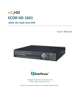
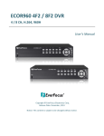
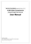
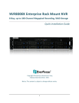
1.1 Overview
Front View
Rear View
Power Supply
USB3.0
Key
USB2.0
Internal HDDs (Optional)
Network
Router / Switch
Mouse /
USB Memory Stick
IP Camera
EverFocus Genie
XMS CMS
Figure 1-1
1.2 Features
•
•
•
•
•
•
•
Elite 2 NVR8004X can support up to 16 channels
Hard Drive Configurations in 2 / 4 / 8 / 12 TB
4 HDD Bays with removable hot swap trays
Dual NIC for separation of streaming camera video form LAN / WAN monitoring network
Built-in web server for single NVR live / playback viewing and configuration
Raid: 0, 1, 5 and 10 configurable
Free multi-site CMS displays live and playback video for up to 128 live and 16 playback
cameras (dual monitors permit 2 x 64 live views; playback screen replaces one live view)
from any combination of Elite 2 and Commander 2
2
Elite 2 NVR8004X
1.3 Packing List
• NVR x 1
• CD x 1 *see note 3
• Quick Guide x 1
• Mouse x 1
• Power Cord x 1
• Adaptor x 1
• Standard RJ45 cable x 1
• Sticker x 1 *see note 4
• Screw x 16 *see note 4
• Key x 2 *see note 4
Note:
1. Equipment configurations and supplied accessories vary by country. Please consult your
local EverFocus office or agents for more information. Please also keep the shipping
carton for possible future use.
2. Contact the shipper if any items appear to have been damaged in the shipping process.
3. The CD contains the IP Utility software, EF Player, JAVA software, Quick Installation
Guide, and User’s Manual.
4. The Sticker, Screws and Keys are contained in the HDD trays respectively.
1.4 Optional Accessory
•
EKB200 (USB controller keyboard: connect to the PC to control the PTZ camera connected
to the NVR).
3
Elite 2 NVR8004X
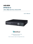
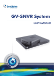
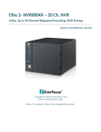
1.5 Front Panel
1
2
3
4
Figure 1-2
No. Name
1
Status LED
2
3
4
Power
HDD Tray
Lock
Description
SYS: Indicates the system is working.
EXT: Indicates the NVR is connected to the external storage device or
USB dongle.
LAN1 / LAN2: Indicates the NVR is connected to the network.
HDD1~4: Indicates the internal HDD is activating, but the LED
indicators will light up only if you install the HDDs before turning on
the NVR. If the NVR is already on and you hot-swap the HDDs, the
HDD1~4 LED indicators will still remain on / off as the previous status,
please see the example in the note below.
PWR: Indicates the power is on.
Press to turn on / off the NVR.
Pull the HDD tray out to install the HDD.
Use the supplied key to lock / unlock the NVR.
Note: For example, if the HDD1 is installed before turning on the NVR, the HDD1 LED
indicators will emit light once the NVR is powered on. Then, if you hot-swap either one of
HDD1~4, still only the HDD1 LED indictor remains light up. You can reboot the NVR manually
and the HDD LED indication will be corrected.
4
Elite 2 NVR8004X
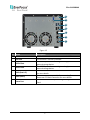
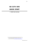
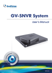
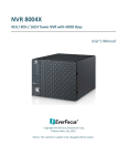
1.6 Rear Panel
1
2
3
4
5
6
7
Figure 1-3
No. Name
1
Reset
2
VGA Port
3
USB3.0 Port
4
USB2.0 Port
5
LAN2 (Static IP)
6
LAN1 (DHCP)
7
Power Port
Description
Insert a tool into the reset hole to reset the NVR.
The function is currently reserved.
The USB3.0 ports for connecting to a dongle, mouse or
external storage device.
The USB2.0 ports for connecting to a dongle, mouse or
external storage device.
Connects to the Network. Please see 2.2 Basic Connection
for more details.
Connects to a router or switch for connecting IP cameras.
Please see 2.2 Basic Connection for more details.
Connects to the 19 VDC power using the supplied Power
Cord.
5
Elite 2 NVR8004X
Chapter
2
2.
Installation
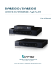
2.1 Hard Disk Drive Installation
1. Make sure the NVR is power-off, and open the cover on the front panel of the NVR.
2. Press the release latch, and the locking arm pops up.
Release Latch
Locking Arm
Figure 2-1
3. Gently pull the locking arm to take out the HDD tray.
Figure 2-2
4. Insert 2.5” or 3.5” HDD in the tray.
HDD Tray
Figure 2-3
6
Elite 2 NVR8004X
5. Secure the HDD with the supplied 4 screws to the tray.
a. 3.5” HDD:
Figure 2-4
b. 2.5” HDD:
Figure 2-5
6. Push the HDD tray into the drive bay of the NVR with the locking arm unlatched.
Figure 2-6
7. Close the locking arm until you hear a click.
Figure 2-7
8. Close the cover of the NVR.
7
Elite 2 NVR8004X
2.1.1 Hard Disk Compatibility List
Please use the hard disk models recommended in the list below to ensure your hard disks will
be compatible.
Note: If using two or more hard disks, please choose the hard disks with the same
capacity.
SATA Hard Disk
Seagate
Western Digital
Model
SV35.5 SATA2 ST3500410SV
SV35.5 SATA2 ST31000525SV
SV35.5 SATA3 ST3500411SV
SV35.5 SATA3 ST31000526SV
SV35 SATA3 ST2000VX002
Constellation ES.3 SATA3
ST4000NM0033
Constellation CS SED SATA3
ST3000NC000
CE-Video SATA3 / ST3500312CS
CE-Video SATA3 / ST1000VM002
CE-Video SATA3 / ST2000VM003
CE-Video SATA3 / ST3000VM002
CE-Video SATA3 / ST4000VM000
ST4000VX000
Capacity
500GB
1TB
500GB
1TB
2TB
WD40PURX-64GVNYO
WD30PURX-64P6ZY0
WD20PURX-64P6ZY0
WD10PURX-64D85Y0
WD10EVDS SATA2
WD10EURS SATA2
WD10EURX SATA3
WD20EVDS SATA2
WD20EURS SATA2
WD30EURS SATA2
WD10EVVS SATA
WD20EFRX
WD30EFRX
WD4001FAEX
WD1600AVVS SATA
WD3200AVVS SATA
WD5000AVVS SATA
WD7500AVVS SATA
WD10EVVS SATA
4TB
3TB
2TB
1TB
1TB
1TB
1TB
2TB
2TB
3TB
1TB
2TB
3TB
4TB
160GB
320GB
500GB
750GB
1TB
8
4TB
3TB
500GB
1TB
2TB
3TB
4TB
4TB
Elite 2 NVR8004X
Toshiba
MD03ACA200V
MD03ACA300V
MD03ACA400V
DT01ABA050V
DT01ABA100V
DT01ABA200V
DT01ABA300V
MG03ACA100
MG03ACA200
MG03ACA300
2TB
3TB
4TB
500GB
1TB
2TB
3TB
1TB
2TB
3TB
9
Elite 2 NVR8004X
2.2 Basic Connection
The instructions below describe the connection for the Elite 2 NVR8004X.
Front View
Rear View
5
3
USB3.0 USB2.0
1
Internal HDDs (Optional)
Power Supply
4
Network
Router / Switch
2
Mouse /
USB Memory Stick
EverFocus
Genie XMS CMS
IP Camera
Figure 2-8
1. Install 1 to 4 HDDs (Please refer to 2.1 Hard Disk Installation).
2. Optionally connect a Mouse and USB Memory Stick to the NVR.
3. To manage the NVR over network, it’s recommended to connect the supplied standard
RJ-45 cable from your network to LAN2 port.
4. To connect IP cameras, please use a router or switch to connect between NVR and IP
cameras. It’s recommended to connect the router or switch to the LAN1 of the NVR.
5. Using the supplied Power Cord, connect one end to the 19 VDC port on the NVR and the
other end to the power outlet.
Note: Before powering on the NVR, please install the HDDs first. Please see 2.3 USB
Dongle Connection and 2.4 Turning On / Off the Power for more details.
2.3 Turning On / Off the Power
Before powering on the NVR, please make sure the internal HDDs have been installed
properly. When you have completed the basic cable connections, you are ready to turn on the
NVR.
Once connect the supplied Power Cord to the power outlet, the NVR will be powered on. All
of the LED indicators on the front panel will light up for a second, but the System and Power
LED will remain light up. To turn off the power, simply unplug the Power Cord from the power
outlet. You can also press the Power button inside the front panel to turn on and off the NVR
without unplugging the Power Cord.
10
Elite 2 NVR8004X
2.4
Connecting the NVR to the Network
There are three methods to connect the NVR to the network: Router or LAN Connection, Direct
High‐Speed Connection and One‐to‐One Connection.
2.4.1
Router or LAN Connection
This is the most common connection in which the NVR is connected to a router and allows
multiple users on and off site to see the NVR on a LAN/WAN (Internet). The NVR must be
assigned an IP address that is compatible with its LAN. By setting up port forwarding on the
router, you can remotely access the cameras from outside of the LAN via the Internet.
Straight-through LAN patch cable
Right: Pinout of a straight-through cable.
Figure 2-9
11
Elite 2 NVR8004X
Connection Procedure:
The First step is to purchase or make a straight through cable. We recommend
purchasing one if you have never made a straight through cable. Please remember
you can not use a cross-over network cable for this application.
Once you have a straight through cable, plug one end into the LAN port on the back
of the recorder and the other into the router.
Log into the EverFocus NVR menu and go to the Network Setting Menu.
To let the router automatically assign an address:
Set the Network Type to DHCP. Make sure to write down the IP address and the
Gateway.
Exit from the Menu to save settings.
To manually assign an address:
Go to a computer connected on the same network as the NVR.
Click on the Start button and choose Run.
If using Windows Vista, choose Search instead.
Type “command” and click on OK.
In Vista, you will need to double-click on the “Command Prompt” file to open it.
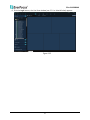
In the DOS prompt, type “ipconfig” and press Enter.
The network information will be displayed on a screen similar to the one below.
In Windows Vista, look for the information that says “IP v4”.
Figure 2-10
12
Elite 2 NVR8004X
Take the values for Subnet Mask and Default Gateway and input them into the
NVR; these values should be exactly the same in both devices. However, you
should change the last number of the IP address. For example, if the IP address
of the computer is 192.168.2.101, the NVR’s IP address should be 192.168.2.50.
To access the NVR from a computer simply open Internet Explorer and in the address
bar type:
http:// (IP address of the NVR)
Note: The NVR’s IP address will only work at the location of the NVR. To connect
from a different location over the Internet, see below.
To set the NVR for Internet Connection through router:
The next step is to open ports within your router. Log into the router using a PC and
open the following ports.
Ports to open: 80
If your Internet service provider blocks port 80, you can change it to a different
port in the NVR’s Network Menu Setup; open/forward that port instead.
If you are using a Linksys or D-Link router, see Appendix B for basic support on
setting up ports. For any other router, you will need to contact the manufacturer
for support.
To access the NVR from a computer simply open Internet Explorer and in the address
bar type:
http:// (the IP address given by your internet service provider)
Note: If you changed to a different port other than 80, you will need to include this
at the end of the IP address:
http:// (the IP address given by your internet service provider):port number
If you have a WAN Dynamic IP address and have opened the ports, go to 6.7.3 DDNS
Setup to configure the DDNS settings.
13
Elite 2 NVR8004X
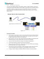
2.4.2
Direct High-Speed Connection
In a Direct High‐Speed Connection, the NVR connects directly to a modem without the
need for a router. You need to set the static or dynamic WAN IP address assigned by your
ISP (Internet Service Provider) in the NVR’s configuration web pages. To access the NVR,
just type “http://xxx”, where xxx is the IP address given by your ISP. If you have a dynamic
IP address, this connection may require that you use DDNS for a reliable connection.
Figure 2-11
Connection Procedure:
The first step is to purchase or make a straight through cable. We recommend
purchasing one if you have never made a straight through cable. Please remember
you can not use a cross-over network cable for this application
Once you have a straight through cable plug one end into the LAN port on the back of
the recorder and the other into the high speed modem.
Log into the EverFocus NVR menu and go to the Network Setting Menu.
Input the Static IP address, the Subnet Mask, and the Gateway that you obtained
from the internet service provider.
Note: If you have a dynamic IP address, you can set the NVR to DHCP to automatically
detect the network settings. Therefore, it can use a dynamic IP address.
Exit from the NVR’s Menu to save the settings.
To access the NVR from a computer, open Internet Explorer and in the address bar
type: http:// (IP address given by your internet service provider)
Note: When using this type of connection, only one device can be connected to the
modem at a time. You will need to use a computer at a different location to test the
connection s.
14
Elite 2 NVR8004X
2.4.3
One-to-One Connection
You can connect directly without using a switch, router or modem. However, only the PC
connected to the NVR will be able to view the NVR. You will also have to manually assign a
compatible IP address to both the computer and the NVR. Unless the PC has another
network connection, the NVR will be the only network device visible to the PC. See the
diagram below:
Right: Pinout of a crossed-over cable.
Figure 2-12
Connection Procedure:
The First step is to purchase or make a cross-over cable. We recommend purchasing
one if you have never made a cross-over cable. Please remember you can not use a
straight through network cable for this application.
Once you have a cross-over cable, plug one end into the LAN port on the back of the
NVR and the other into the network card on the back of the computer.
Log into the EverFocus NVR menu and go to the Network Setting Menu.
You must use the Static IP option for this type of connection.
Assign an IP of 192.168.001.003, a Subnet Mask of 255.255.255.000, and a Gateway
of 192.168.001.001. You can ignore DNS Server.
The next step is to set the computer’s network settings to match those of the NVR.
You will need Administrator privileges on your Windows machine to do this.
To assign a fixed IP address in Windows 2000/XP, follow the instructions below:
15
Elite 2 NVR8004X
Go to Start. Double-click on Control Panel.
Figure 2-13
Click Network and Sharing Center.
Figure 2-14
Click Local Area Connection.
Figure 2-15
16
Elite 2 NVR8004X
Click Properties.
Figure 2-16
Click on Internet Protocol Version 4 (TCP/IPv4) and then click Properties.
Figure 2-17
17
Elite 2 NVR8004X
Select Use the following IP address. Assign an IP address of 192.168.1.2, a
Subnet Mask of 255.255.255.0, and a Default Gateway of 192.168.1.1 and then
click OK.
Figure 2-18
Restart both of the computer and the NVR.
To access the NVR from the computer, simply open Internet Explorer and in the
address bar type: http://192.168.1.3
18
Elite 2 NVR8004X
2.5 Checking the Dynamic IP Address
You can look up the IP address and access the Web interface of the NVR using the IP Utility
(IPU) program, which is contained in the CD. It can also be downloaded from EverFocus’
Website: http://www.everfocus.com/HQ/Support/DownloadCenter_p1.aspx. Please connect
the NVR in the same LAN of your computer.
1. Install and then start the IPU program
. The following dialog box appears.
Figure 2-19
2. IPU will automatically search the IP devices connected in the LAN. The default network
values of the IP devices will be displayed. By default, the network protocol of the IP device
is DHCP.
3. To optionally configure the Machine Name, IP Address, IP Type or Port Number using the
IPU:
a.
Log in the NVR by checking the desired model and then click the Log in
Log in dialog box appears.
icon. The
Figure 2-20
b. Type the Username and Password. Click the OK button, the status of the selected
camera will display Login.
Figure 2-21
Note:
1. The default user ID is admin and the default password is 11111111.
2. If you select more than one NVRs that have the same user ID / password, you will
be able to log in several NVRs at once.
19
Elite 2 NVR8004X
c.
Right click the column to configure the setting. Click Apply Changes
apply and save the settings.
button to
Figure 2-22
Note: Most networks uses DHCP to assign IP address, if you are unsure of your
network settings, please consult your network administrators for configuration
details.
4. To access to the Live View window, open a Google Chrome Web browser, type the IP
address of the NVR in the address field and press the Enter key on the keyboard, the
Welcome window pops up. Follow the instruction steps to update the latest Plugin version.
Figure 2-23
Note: The Welcome window will only be prompted for the first time login in order to
update the system to the latest plugin version.
5. After reloading the webpage, the login window pops up. Type the user ID and password to
log in. By default, the user ID is admin and the password is 11111111.
Figure 2-24
20
Elite 2 NVR8004X
6. Click the Login button, the Live View window (see 3.2 Live View Window) appears.
Figure 2-25
21
Elite 2 NVR8004X
Chapter
3
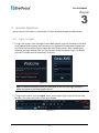
3. General Operation
You can view the live videos or operate the Live View Window through the Web browser.
3.1 Login / Logout
1. To log in the system, open a Google Chrome Web browser, type the IP address of the NVR
in the address field and press the Enter key on the keyboard, the Welcome window pops
up. Follow the instruction steps to update the latest Plugin version. After reloading the
webpage, the login window pops up. Type the user ID and password to log in. By default,
the user ID is admin and the password is 11111111.
Figure 3-1
Note: The Welcome window will only be prompted for the first time login in order to
update the system to the latest plugin version.
2. To log out the system, click the Logout button on the upper-right corner of the Live View
Window. The system will return to the login window.
Figure 3-2
22
Elite 2 NVR8004X
3.2 Live View Window
2
21
23
25
7
5
3
1
4
6
8
9 10
13
11
14
12
15
16
17
18 19
22
24
26
27
28
Figure 3-3
No. Name
1
List
2
Menu Tree
3
Group
4
Ratio
5
6
7
8
eMap
OSD Display Mode
Expand / Collapse
Full Screen
9
Option
10
Device Detail
Description
Click to display the Device List
Click to show / hide the Menu Tree of the Device List.
Click to configure the Group settings (see 3.2.3.1 Group
Settings).
Click to switch live video ratio between original (source video)
and extended (to the layout screen).
Click to display the eMap (see 3.2.1 eMap).
Click to show / hide the information of device name and time.
Click to expand or collapse the Device List.
Click to display the Live View layout in full screen.
Click to show / hide the Live View Tool Bar at the bottom of
each cell. See 3.2.2 Live View Tool Bar for more details.
Click to enter the Device List setup page (see 3.2.3 Device List
23
20
Elite 2 NVR8004X
Setup).
11
12
13
14
15
16
17
18
19
20
21
22
23
24
25
26
27
28
Click to display the Live View layout.
Click to enter the playback page for multi-channel playback.
Click to disconnect the live streams.
Click to enter the Event List setup page.
This function is optional. Click to enter the Access Control
Access List
setup page.
This function is optional. Click to enter the Intelligent Video
IVS
Surveillance (IVS) setup page.
Click to enter the Settings page (see 3.5 Setting).
Setting
Click to save the current live layout as a Page in the Page List
Add
(see 3.2.5 Page Setting).
Click to log out the system.
Logout
Click to switch the theme between the dark and light.
Theme Switch
Click to enter the Layout Design page. You can further create
or modify the personal layout design (see 3.2.4 Layout
Layout Detail
Setting).
Click to enter the layout page for layout selection (see 3.2.4
Layout
Layout Setting).
Click to enter the PTZ setup page.
PTZ Detail
Click to display the PTZ Control panel.
PTZ Control
Click to enter the Page setup page (see 3.2.5 Page Setting).
Page Detail
Click to display the Page List (see 3.2.5 Page Setting).
Page
Click to display the Time Search calendar for playback.
Time Search
Digital Zoom / Fisheye Click to enter the Digital Zoom / Fisheye operation page.
Live View
Playback
Close Stream
Event List
24
Elite 2 NVR8004X
3.2.1 eMap
On the Live View Window, click the eMap button, the eMap page appears.
1
2
3
4
Figure 3-4
No.
1
2
3
4
5
Name
List
Select
Delete
Save
Clear
Description
Click to display the eMap list.
Click to select an eMap picture (PNG, JPG, JPEG, GIF, TIFF).
Click to delete an eMap.
Click to save the settings.
Click to clear the eMap settings.
25
5
Elite 2 NVR8004X
3.2.2
Live View Tool Bar
You can use the Live View Tool Bar to control the main / sub streams, local recording, audio,
snapshot and playback of the IP camera. On the Live View Window, click the Option button,
the Live View Tool Bar appears on the top of the live view cell.
1
2
3
4
5
6
7
Figure 3-5
No. Name
1
Stream Type
2
Record
3
Audio (Speaker)
4
Snapshot
5
Microphone
6
Quick Playback
7
Close
Description
Click to switch between main and sub stream.
Click to start / stop local recording. You have to set up the
recording path for the recordings in advance (see 3.3.1 Setting up
the Recording Path).
Click to transfer the sound from the device to the client side
(remote client PC) if the speakers have been connected to the
device. Note that a (built-in) amplifier and external power supply
are required for the speakers.
Click to take a snapshot. You have to set up the recording path for
the snapshots in advance (see 3.3.1 Setting up the Recording
Path).
Click to transfer the sound from the client side (remote client PC)
to the device if the microphones have been connected to the
client side. Note that a (built-in) amplifier and external power
supply are required for the microphones.
Click to display the Quick Playback Bar for playing back (see 3.4
Quick Playback).
Click to disconnect the stream.
26
Elite 2 NVR8004X
3.2.3
Device List Setup
You can configure and manage the device list using this page. On the Live View Window, click
the Device Detail button, the Device List Setup page appears on the right window.
1
2
3
4
5
7
6
8
9
10 11
12
Figure 3-6
No. Name
1
Device Detail
2
Device
3
Group / List
4
Edit / View
5
6
7
Export
Load Template
Total
8
Device Type List
9
Import
10
Delete
11
Add
12
Device Indicator
Description
Click to enter the Device List setup page.
Click to display the Device List.
Click to switch between Group view and List view for the
Device List. You can also setup the Group settings (see 3.2.3.1
Group Settings).
Click to switch between Edit and View mode for the Device List.
For editing the added devices, see 3.2.3.2 Editing Device
Configurations.
Click to export the Device List file (.csv).
Click to download the Device List Template (.csv).
Display the current number of the connected devices.
Click the drop down list and select the desired device type (see
3.2.3.3 Device Type List).
Click to import the Device List file (.csv).
Select the desired devices and click the Delete button to
remove the devices from the Device List.
Click to enter the Maintain page for adding devices. For more
details on adding devices, see 3.2.3.4 Adding Devices.
The Device Indicator indicates the status of the devices (see
3.2.3.5 Device Indicator).
27
Elite 2 NVR8004X
3.2.3.1
Group Settings
You can configure the group settings on this page.
Figure 3-7
1.
On the Device List setup page, click the Group button, and then click the Group folder on
the Group List, the modification icons appears.
2.
Click the add node
3.
Drag a device from the Device List and drop it to the created group. You can drag multiple
devices to a single group.
4.
Click the Save button to save the settings.
button and enter a name to add a node.
28
Elite 2 NVR8004X
3.2.3.2
Editing Device Configurations
To edit the added devices, on the Device List Setup page, click the
Edit icon, click the
column you want to configure and input the setting. Click the Update button to save the
settings.
Figure 3-8
3.2.3.3
Device Type List
You can add devices, image, message or even a Website to the system. On the Device List Setup
page, click the Device Type List drop-down list to select a device type.
No.
1
2
3
4
5
6
7
8
9
10
Name
IPCAM
DVR
NVR
Message
RTSP
Image
Access
Access Server
XMS
WEB
Description
IP camera.
EverFocus DVR.
EverFocus NVR.
Display message for Text or Marquee mode.
RTSP streaming URL.
Picture (PNG, JPG, JPEG, GIF, TIFF).
Access controller or reader.
ENS200 Access management server.
EverFocus XMS server.
Web URL.
29
Elite 2 NVR8004X
3.2.3.4
Adding Devices
You can manually or automatically add devices to the NVR. On the Device List Setup page, click
the Add button, the Maintain page appears.
Manually Adding a Device
Select a device type from the Device Type drop-down list, enter the device information and
click the Save button to save the settings. The device will be added to the Device List.
Figure 3-9
Automatically Adding Devices
On Figure 3-9, click the
Auto Detection icon to switch to the Auto Detection page.
Figure 3-10
1.
Check the square beside the Device Name to select a desired device. (Note: If multiple
devices have the same ID and Password, you can select multiple devices on this step).
30
Elite 2 NVR8004X
2.
Type the device ID and Password in the above columns.
3.
Click the
devices.
4.
Click the Authentication icon, the verified devices will be marked with a check mark.
5.
Click the Save button, the device will be listed on the Device List.
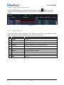
3.2.3.5
Apply to Select icon to apply the input ID and Password to the selected
Device Indicator
The Device Indicator indicates the status of the devices.
Status
Connected
Recording
Event Triggered
No Connection
Disconnect
Description
Indicates the devices have been connected with streaming
displayed.
Indicates the live view recording (schedule record) is on.
Indicates an event occurs or an alarm is triggered.
Indicates there is no connection of this device.
Indicates the devices have been disconnected.
31
Elite 2 NVR8004X
3.2.4
Layout Setting
You can configure the layout on this page. On the Live View Window, click Layout from the
left-side bar, select a layout by clicking on the desired layout, the selected layout should be
appeared on the right-side window.
To add the devices to the layout cells, on the left-side bar, click Device, drag and drop the
devices from the Device List to the layout cells.
Figure 3-11
To create personalized layout, on the left-side bar, click the
Layout Detail button, select
an editable layout and click the Add button, an edit bar should appear on the top of the
window. Use the function buttons to add/delete/merge/separate layout cells. Click the
Save icon to save the settings.
32
Elite 2 NVR8004X
3.2.5
Page Setting
You can create multiple live view layouts and then save them as pages. Create a layout and
then click the Add icon on the Live View Window. The layout will be saved in the Page List as a
page.
Figure 3-12
To modified pages, on the Live View Window, click the Page Detail button on the left-side bar
and then click the Update button.
33
Elite 2 NVR8004X
3.3
Recording
You can set up a weekly recording schedule for the connected devices to record the videos in
your computer. The recordings will be saved in AVI files. You have to set up a recording path for
the recordings before activating this function (see 3.3.1 Setting up the Recording Path).
On the Live View Window, click the Setting button, click the Record & Play menu bar on the left,
click Schedule, the following Schedule page appears.
Figure 3-13
Recording Type buttons:
: Continuous recordings only.
: Event recordings only.
: Continuous and Event recordings.
Note: For Event recordings, you have to configure the event settings in advance. On the Live
View Window, click the Setting button and then click Event on the menu bar to enter the
Event Setting page. For motion detection setting, please refer to 3.5.7 Motion Detect.
To add a recording schedule to the Schedule Name List:
1.
Select a recording type by clicking on the Recording Type buttons.
2.
Move the cursor on a desired time square, click and drag the cursor to set up the time
period on each day. The squares will be displayed in blue/yellow/green to indicate which
recording type has been applied to the time period.
3.
Click the Add button and enter a name for the recording schedule.
4.
The recording schedule should be listed in the Schedule Name List.
34
Elite 2 NVR8004X
To apply a recording schedule to the desired devices:
1.
Click the Device List button, select the desired devices and then click the Save button.
2.
Select a desired recording schedule from the Schedule Name List drop-down list and then
click the Apply button.
3.3.1
Setting up the Recording Path
On the Live View Window, click the Setting button, click the User Setting menu bar on the left,
click Local Save Settings, the following page appears. Click the Select button in the Save
Recording in field to select a path for the recordings. Click the Apply button to save the settings.
You can also set up a path for the snapshot images in the Save Snapshot in field.
Figure 3-14
35
Elite 2 NVR8004X
3.4
Quick Playback
You can play back the Live View recordings of the cameras stored in the client computer using
the internal built-in player. On the Live View Window, click the Option button, the Live View
Tool Bar appears on the top of the live view cell. Click the Quick Playback button, the playback
bar appears on the button of the window. You can control the playback bar on this page.
Figure 3-15
The Quick Playback function is designed to play back the recordings start from the
pre-configured time. Before using the Quick Playback function, you have to configure the
Playback settings in advance. On the Live View Window, click the Setting button, click Record &
Play from the menu bar and click Playback, the Playback setup page appears. Enter the desired
time for playing back the recording. Take the below image for example, if the current system
clock time is 17:35:00, the start time for the playback recording will start from 17:34:00 (60
seconds ago from 17:35:00).
Figure 3-16
36
Elite 2 NVR8004X
3.5
Setting
You can configure the system settings on this page. On the Live View Window, click the Setting
button, a menu bar appears on the left side of the window. Enter each field to configure the
settings.
Figure 3-17
37
Elite 2 NVR8004X
3.5.1
Date / Time
On the left-side menu bar, click System Setting and then click Date/Time. Enter the current
date and time, and then click the Apply button to save the settings.
Figure 3-18
3.5.2
License
On the left-side menu bar, click System Setting and then click License. Enter the data, and then
click the Activate button to activate the license.
Figure 3-19
38
Elite 2 NVR8004X
3.5.3
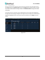
User Management
You can create multiple user accounts with different privileges using this page. On the left-side
menu bar, click User and then click User Management. Click Change Mode, click the Add
button to add a user, input the password for the user, select a user group from the drop-down
list and then input the email address of the user. Click the Save button, the user should be
listed in the User Management list.
Note that there are three group types for the user account: Administrator, Operator and Viewer.
Each group type is applied with the fixed privileges as listed below.
Figure 3-20
39
Elite 2 NVR8004X
3.5.4
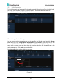
Recording Data Report
This Recording Data Report shows the recording status of all the devices. On the left-side menu
bar, click System Information and then click Recording Data Report. Click to select a Date and
Time, click Related Device List to select devices, and click Query to display the recording status
report. You can click By Minutes/ Second or By Hour to show the report in different timeline
formats.
: A yellow block represents only events are recorded during this time block.
: A green block represents the continuous and event recording during this
time block.
: A blue block indicates the continuous recording during this time block.
: A red block may result from disconnection, power-loss or ongoing recording
during this time block.
Figure 3-21
40
Elite 2 NVR8004X
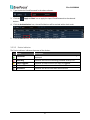
3.5.5
Disk Information
This Disk Information will automatically show the detailed information of all the installed hard
disk drives, such as model name, disk type and capacity. On the left-side menu bar, click
Storage Device and then click Disk Information.
Figure 3-22
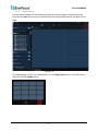
3.5.6
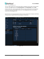
Storage Device Management
You can manage all the storage devices on this page. On the left-side menu bar, click Storage
Device and then click Storage Device Management. Click Format to format the HDD for the
first time. (WARNING: This will effectively ERASE the ENTIRE hard disk!) Click Add to add a new
group, enter a group name, and then drag and drop the disks from the Unused Group to the
newly created group. Click Apply to group the disks.
Note that one disk can only be added to one group.
Figure 3-23
41
Elite 2 NVR8004X
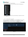
You can also configure the detailed settings for each group.
Figure 3-24
Auto Erase Recording / Day(s): The hard disk will automatically erase video after it has been on
the hard drive for the entered number of days.
Overwrite: Check the box to overwrite the hard disk when the capacity is used up to 99% (the
capacity does not include the locked space of the disk).
Lock %: Enter a percentage for a write protected segment of the hard disk (will not be
overwritten). However, this locked space is currently reserved.
For example, if you check the Overwrite box and you set 20% of the locked disk space, when
the disk is used up to 99% of the remaining 80% unlocked space, it will start overwrite the disk.
To save the IP camera recording to this disk group, please see below:
1.
Go to the Live View page by clicking the
Device Detail.
Live View button, and then click
Figure 3-25
42
2.
Elite 2 NVR8004X
Double-click a device to display the device setting, and then click Storage Device to select a
desired disk group.
Figure 3-26
3.
Click the
Save button on the upper-right corner of the page.
Figure 3-27
43
Elite 2 NVR8004X
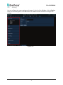
3.5.7
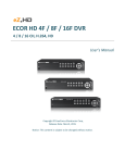
Motion Detect
You can set up the motion detection of the IP camera on this page. On the left-side menu bar,
click Event and then click Motion Detect. Check the Enable box on the devices which you want
to set up the motion detection setting, and then click Edit Motion Grid to bring up the motion
setting page.
On the left side, click on a device or select multiple devices and its image will be displayed at
the right side. Click and drag a rectangle on the image to set up a motion area, and the selected
area will be highlighted in blue. You can only set up one motion area. Click Apply to save the
setting.
Figure 3-28
44
Elite 2 NVR8004X
Chapter
4
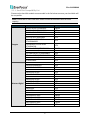
4. Specifications
Model
System
Channels
OS
Elite 2 NVR8004X
Comes with 4 Licenses (Expandable to 16)
Embedded Linux
Can duplicate cameras with Digital Zoom/Digital PTZ views for each
View Mode
separately
Continuous record, record by schedule, event trigger record, digital
Recording Modes
input trigger record
Up to full camera resolution
Recording Resolution
Compression Supported H.264 / MJPEG
Bi-directional transmission, 1 audio channel per video channel
Audio
(depending on specification of IP device)
Live View up to 128 Streams
Max Client Limit
Storage
4 SATA II HDD bays with Removable Hot Swap Trays
Internal HDD
up to 12TB
Video Storage
0,1, 5, 10 configurable
Raid
Interface
Gigabit RJ45 Ethernet Port x 2
Network Interface
USB 2.0 x 2; USB 3.0 x 2 (on back panel)
Other Interface
Dependent on supported camera
Alarm I/O
Function
Yes
Event Trigger
Dependent on supported camera “On Screen Display” for event
Notification
notification, Trigger alarm output , send email notification
Supports E-map with device indicator
E-Map
Displayed in Client Screen
Bandwidth Monitor
Create unique user ID and password with user rights management
User Rights
for per camera live &/or playback access; restrict ability to backup
Management
and/or delete data
PTZ Control of supported cameras
PTZ
Can zoom to selected view on any camera
Digital PTZ
Max 100Mbps, Max 30 FPS per camera
Recording Rate
45
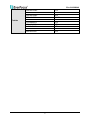
Multi-Channel
Multi-Channel
Playback:
Elite 2 NVR8004X
Live view any camera in any cameo. Duplicate cameras for digital
PTZ view. Web Browser view up to 128 cameos.
Up to license limit/max 16 cameras simultaneous on screen
Time/Date via calendar and time bar; Intelligent search with modes:
general motion, missing object, camera occlusion, foreign object,
Search Function
signal lost
Snapshot in JPEG format; video export in AVI format
Video Export to:
Live view: Max 128 cameos (up to 2 windows with up to 64 views on
each monitor at 1 PC)
Playback view: up to 16 cameras (replaces one Live View screen
during playback at PC)
Remote Video Access
via Free Client Software PC Remote backup function (multiple channel backup up to 16
channels)
Mobile phone/PDA/tablet: free app with live multi views (No limit
for number of installations for all remote applications)
Internet Explorer 9 and later, Firefox 4.0-9.0, Chrome (Windows
Remote Maintenance
version)
Live view, preset/go, PTZ, remote I/O, snapshot, multi-view, digital
Remote Live View
PTZ, advanced E-map, bandwidth control
Control
General
DC 19VDC , 4.74A
Power
90W max; AC to DC power supply included with NVR
Power Consumption
32°F~104°F
Temperature
Compact Desktop Lockable front door
Housing
140 mm x 183 mm x 219 mm / 5.51” x 7.16” x 8.62”
Dimensions
2.97 kg / 6.55 lbs (without HDDs)
Weight
CE, FCC
Certifications
Remote Client System
OS
CPU
RAM
LAN Transmission
Speed
Web Client
Mobile iViewer
Minimum Requirement
Windows XP (32-bit) / Win7 (32 and 64-bit) / Mac OS X
Intel Core 2 Duo, 2.6GHz
1GB
10/100/1000 Mbps (RJ45)
Internet Explorer 9 and later, Firefox 4.0-9.0, Chrome (Windows
version)
iPhone, iPad, Android
46
EverFocus Electronics Corp.
EverFocus Taiwan:
12F, No.79, Sec. 1, Shin-Tai Wu Road,
Hsi-Chih, Taipei, Taiwan
TEL: +886 2 2698 2334
FAX: +886 2 2698 2380
www.everfocus.com.tw
[email protected]
EverFocus Europe - Germany:
Albert-Einstein-Strasse 1, D-46446
Emmerich, Germany
TEL: +49 2822 93940
FAX: +49 2822 939495
www.everfocus.de
[email protected]
EverFocus China - Beijing:
Room 609, Technology Trade Building,
Shangdi Information Industry Base,
Haidian District, Beijing 100085, China
TEL: +86 10 6297 3336~39
FAX: +86 10 6297 1423
www.everfocus.com.cn
[email protected]
EverFocus China - Shenzhen:
4F, No. 2, D4 Building, Wan Yelong
Industrial Park, Tangtou Road, Shiyan,
Baoan, Shenzhen, Guangdong 518101, China
TEL: +86 755 2765 1313
FAX: +86 755 2765 0337
www.everfocus.com.cn
[email protected]
EverFocus USA - California:
1801 Highland Avenue, Unit A, Duarte, CA 91010, USA
TEL: +1 626 844 8888
FAX: +1 626 844 8838
www.everfocus.com
[email protected]
EverFocus USA - New York:
415 Oser Avenue, Unit S, Hauppauge, NY 11788, USA
TEL: +1 631 436 5070
FAX: +1 631 436 5027
www.everfocus.com
[email protected]
EverFocus Japan:
3F Kuramochi, Building II 2-2-3
Koto-Bashi,Sumida-ku, Tokyo,130-0022,Japan
TEL: +81 3 5625 8188
FAX: +81 3 5625 8189
www.everfocus.co.jp
[email protected]
EverFocus China - Shanghai:
Room 403, Ruijin Business Center, No.96,
Zhaojiabang Road, Luwan district, Shanghai 200020,
China
TEL: +86 21 6471 2229 / 6471 2291
FAX: +86 21 6471 0566
www.everfocus.com.cn
[email protected]
EverFocus India:
UBS, 629/1243, 1st Floor, G Block, Behind Teacher’s
Colony,Bandra Kurla Complex, Bandra (E),
Mumbai 400 051, India
TEL: +91 22 6726 4500
FAX: +91 22 6726 4518
www.everfocus.in
[email protected]
Your EverFocus product is designed and
manufactured with high quality materials
and components which can be recycled
and reused.
This symbol means that electrical and
electronic equipment, at their end-of-life,
should be disposed of separately from
your household waste.
Please, dispose of this equipment at your
local community waste
collection/recycling centre.
In the European Union there are
separate collection systems for used
electrical and electronic product.
Please, help us to conserve the
environment we live in!
Ihr EverFocus Produkt wurde entwickelt
und hergestellt mit qualitativ
hochwertigen Materialien und
Komponenten, die recycelt und wieder
verwendet werden können.
Dieses Symbol bedeutet, dass elektrische
und elektronische Geräte am Ende ihrer
Nutzungsdauer vom Hausmüll getrennt
entsorgt werden sollen.
Bitte entsorgen Sie dieses Gerät bei Ihrer
örtlichen kommunalen Sammelstelle oder
im Recycling Centre.
Helfen Sie uns bitte, die Umwelt zu
erhalten, in der wir leben!
P/N: 4605PNV804B063A