1
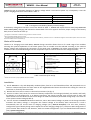
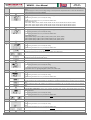
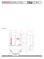
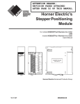
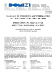
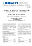
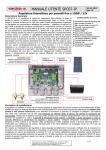
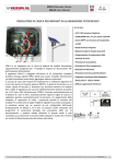
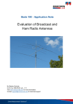
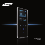
Rev. 1.2
18-03-2014
WRM30 – User Manual
PV CHARGE CONTROLLER
WRM30
Features:
•
•
•
•
•
•
•
•
•
•
•
•
•
•
•
•
•
•
•
•
•
WRM30 is a PV charge controller for big off-grid systems. It is suitable for
12V/24V/48V systems and it can handle a photovoltaic power up to 1.5/1.8kW.
WRM30 has been properly designed for industrial applications such as the
power supplying of either TV/radio bridges, road signs, or whole houses
completely off-grid.
WRM30 implements a research circuit for the maximum power of panel
(MPPT): regardless of battery voltage and its state of charge, the charge
controller makes always the PV module work at its point of maximum power
maximizing the energy extracted from the PV module and charged into the
battery. Charging is temperature-compensated.
•
Special feature of this product is the presence of two separated charging
channels and, therefore, a double input for PV modules. This allows the
management of two independent strings, for example in the case they are
composed of modules with different features or exposed on two slopes, or,
with identical strings, channels can be paralleled thus optimizing efficiency.
The load output can be activated according to several programs that can be
selected by the user: load ON 24h/24h, load ON only during the day, load ON
only during night and load ON during night for a number of hours from 1 to 16.
WRM30 detects the day/night status according to the PV module’s voltage; so
it is not necessary to connect additional sensors to the controller.
It is equipped with a RS485 serial interface through which you can access all of
the available functionalities.
12V / 24V and 48V battery voltage
12V / 24V / 48V auto detect.
MPPT charge
Max charge current: 30A
For sealed/GEL, flooded lead acid
batteries and lithium-ion batteries
(from rev 1.1)
Charge voltage compensated in
temperature
Integrated blocking diode
Max power of PV modules: 450W@12V
/ 900W@24V / 1800W@48V.
Max Voc voltage on PV modules: 150V.
Double input of PV modules.
Configurable parameters by two
buttons and LCD
18 load management programs
Maximum load current: 15A.
Low battery protection
Over temperature protection.
Battery reverse polarity protection.
Overload protection on output.
RS485 interface.
IP20 metal box
Terminals for battery cables 35sqmm
Terminals for PV modules cables
10sqmm
Terminals for load cables 4sqmm
This document is the property of WESTERN CO. Srl - All rights are reserved - Reproduction and use of information contained within this document is forbidden without the written consent of WESTERN CO. Srl
13
Rev. 1.2
18-03-2014
WRM30 – User Manual
General description
WRM30 is a PV charge controller for either sealed (SEAL) or flooded lead acid (FLOOD) electrochemical lead batteries.
From firmware version 1.1 onwards we introduced the charge program for lithium-ion batteries (Li-Ion) with integrated
Battery Management System (BMS); I advise you to contact Western Co. to select the right lithium-ion battery to
connect to WRM30 charge controller. It is absolutely forbidden to connect to WRM30 lithium-ion batteries without
BMS; the BMS protects the battery from unsafe operating conditions that can lead to battery’s explosion or burning.
In fig. 1 there is a principle diagram of WRM30.
2
1
3
5
6
4
Fig. 1 Principle diagram
1- Charging circuit: it consists of two identical but distinct channels. It adapts VPAN and IPAN (respectively voltage and
current of the PV module) in order to search for the condition in which the power delivered by the PV module is
maximum, realizing what in the technical literature is indicated with the acronym MPPT (Maximum Power Point
Tracking). It also manages the battery charging reducing the current delivered to the battery in the conditions in
which the voltage Vbatt equals its charging voltage VEoC.
2- Parallel/Independent: this external connection1 must be inserted when you have either a single photovoltaic field or
a separated one but on a single flap. With the external jumper the charge controller sees a single photovoltaic field
and distributes power equally between the channels. In a system with two slopes or in any case where you want to
maintain the channels independent, the jumper must not be inserted and the charge controller will search for two
different MPPT2.
3- Protections: The switches act as an anti-reverse battery protection and blocking diode. They avoid that during the
night, when the PV module is not illuminated, it can absorb current from the battery. Internal fuses provide an
additional degree of protection.
4- Load: the load3 is power supplied with the same battery voltage and it is controlled through a semiconductor switch.
5- Microprocessor: it controls the whole circuit; it measures currents and voltages of PV modules, battery and load, and
it shows them on the display.
6- For a more precise detection of battery voltage and temperature, WRM30 uses a sensor to be positioned close to the
terminals of battery (the sensor is supplied: SPC20.S). It is important to connect this sensor to guarantee the
compensation in temperature of the end-charge voltage of the system (VEoC) and for a measure of battery voltage
independent of the voltage drop on cables. If you do not connect this sensor the system will work equally but the
battery voltage will be measured on the internal terminals of WRM30, while the compensation VEoC in function of the
temperature will not be performed and, prudentially, the VEoC will be set to the minimum value, as if the system
detects a temperature 60°C.
This document is the property of WESTERN CO. Srl - All rights are reserved - Reproduction and use of information contained within this document is forbidden without the written consent of WESTERN CO. Srl
14
Rev. 1.2
18-03-2014
WRM30 – User Manual
WRM30 has got an automatic detection of battery voltage which is executed at power on; consequently it sets the
proper charging parameters as described in table 1.
Battery voltage measured at startup
Detected nominal voltage
10.0V < Vbatt < 16.0V
20.0V < Vbatt < 32.0V
40.0V < Vbatt < 64.0V
Battery at 12V
Battery at 24V
Battery at 48V
Tab. 1 Recognition thresholds of battery nominal voltage
If the battery voltage does not fall in one of the bands on table 1 , WRM30 will report the error E03 (see§ Alarms and
errors of the system); charging and load will be deactivated. If this error appears check for proper voltage of the battery
bank, then re-execute the start-up.
1
The jumper is made with a conductor having a section of at least 2.5 mm2.
Never exceed the PchMax for each channel.
3
The load has got the positive terminal in common with the positive of battery, while the “minus” is switched through the internal switch (never connect the minus
of the load with the minus of the battery!)
2
Choice of PV module
Thanks to its charging circuit with MPPT, WRM30 charge controller allows the use of a wide range of PV modules
ensuring the optimal exploitation of the whole power. The PV module must be selected according to the nominal
battery voltage and respecting the constraints of the panel input of WRM30. The below reported table 2 gives an
indication of the recommended ranges that are accepted in input on each PV channel of the charge controller.
Nominal battery voltage
Features of PV strings @25°C (per channel)
12V
24V
48V
Range
Vmp: voltage at maximum power
VOC: open circuit voltage
PMAX: max power
Ncs : number of cells in series1
15,0V≤Vmp≤30V
<40V
< 225W
36≤ Ncs ≤60
Vmp: voltage at maximum power
VOC: open circuit voltage
PMAX: max power
Ncs : number of cells in series1
Vmp: voltage at maximum power
VOC: open circuit voltage
PMAX: max power
Ncs : number of cells in series1
30,0V≤Vmp≤60V
<80V
< 450W
72≤ Ncs ≤112
60,0V≤Vmp≤120V
<140V
< 900W
144≤ Ncs ≤168
Table 2 Selection of PV strings
1
Values refer to mono or poly crystalline silicon PV modules.
Installation
1) Install WRM30 in a dry and adequately ventilated place, fixed on a non-flammable surface and positioned so as to
leave an unobstructed space of at least 10cm in the neighbourhood of device that allows the cooling for natural air
convection or forced by the internal fan.
2) Remove the front cover to access to electrical connections (see fig. 4).
3) Connect in order: load, sensor for measure of battery temperature and voltage (included), PV module, and finally
the battery as in the diagram fig. 2. At battery connection, the charge controller turns on and starts to work. The
cable sections must be chosen so that in each length of cable the maximum permissible voltage drop is less than 3%
of the system nominal voltage (Table 3).
4) You can connect to WRM30 lead batteries with 12V, 24V or 48V nominal voltage. At power on the charge controller
measures the battery voltage, it recognizes the nominal voltage of the battery bank connected to it and it
automatically sets the correct levels of charging voltage (see § General description). The user must, however,
configure the type of battery being used to adjust the correct charging voltage (VEoC). Please set SEAL configuration if
you use either VRLA sealed or GEL batteries, while set FLOOD configuration if you use flooded lead acid batteries
(see § System configuration).
This document is the property of WESTERN CO. Srl - All rights are reserved - Reproduction and use of information contained within this document is forbidden without the written consent of WESTERN CO. Srl
15
Rev. 1.2
18-03-2014
WRM30 – User Manual
5) Set the load management program proper for your own application. Note: do not connect to the LOAD output loads
that absorb a current > 15A, otherwise the system goes into over current protection (E02) and the load is not power
supplied.
6) Mount the supplied cable-clamps so that the weight of the cables is not discharged on the electrical terminals, but on
the same cable-clamp and install the front cover to protect the electrical connections.
1
For the cables of load and battery temperature there are not specific cable glands, they must be anchored with cable ties on those of battery.
Wiring diagram
ref. page 2
point (2)
Recommended section pairs of copper cable that guarantee a
maximum voltage drop of 3% of the battery nominal voltage
Current
Max distance per
couple [m]
@ 12V
10A
20A
30A
Current
Max distance per
couple [m]
@ 24V
10A
20A
30A
Current
Max distance per
couple [m]
@ 48V
10°
20A
30A
Cable section
6
mm2
6,3
3,1
2,1
10
mm2
10,5
5,2
3,5
6
mm2
6,3
3,1
2,1
10
mm2
10,5
5,2
3,5
6
mm2
6,3
3,1
2,1
10
mm2
10,5
5,2
3,5
16
mm2
16,7
8,4
5,6
25
mm2
26,2
13,1
8,7
32 mm2
33,5
16,7
11,2
Cable section
16
mm2
16,7
8,4
5,6
25
mm2
26,2
13,1
8,7
32 mm2
33,5
16,7
11,2
Cable section
16
mm2
16,7
8,4
5,6
25
mm2
26,2
13,1
8,7
32 mm2
33,5
16,7
11,2
Table 3 Choice of cables’ section
Fig. 2 Wiring diagram
System testing
Once made the connections as shown in Fig. 3 it is necessary to test the system.
1) At power on, the display will temporarily indicate the firmware revision (see § System configuration - point 1) and
soon after it will show a screen with the detected nominal voltage of the system (see § Views point 1-b).
2) Make sure that the read voltage corresponds to that of the system. The displaying of the system nominal voltage
can be repeated (see § Views point 1-b).
This document is the property of WESTERN CO. Srl - All rights are reserved - Reproduction and use of information contained within this document is forbidden without the written consent of WESTERN CO. Srl
16
Rev. 1.2
18-03-2014
WRM30 – User Manual
3) Verify that in the main page or in the one dedicated to the reading of battery temperature (see § Views point 5),
the battery icon and the ‘°C’ symbol are not flashing; this to indicate the correct connection of the voltage probe
and the battery temperature.
4) With the PV module exposed to sunlight, check that WRM30 charges the battery going to read the charging current
IchA + IchB (see § Views point2).
5) Check the proper power ON of the load. If the load is ON only during night you can simulate the night by
disconnecting temporarily one of the wires of the PV module. Otherwise you can set temporarily the load
programming at 24h/24h, (see § System configuration point 5).
6) With the load ON, check the current absorbed by it reading the parameter ILOAD in the proper page of LCD (see §
Views point 7).
WARNING: To turn off the system please follow these steps:
1) Disconnect PV modules
2) Wait (~30 sec.) until in the display disappears the animation inside the battery icon (fig. 3 - charging current
indicator )
3) Disconnect battery
If not complied these recommended steps, the WRM30 can be damaged.
Views
WRM30 is equipped with a display and two buttons for the user interface. It is organized in two environments: one for
displaying and one to configure. In the first one there is a main screen which summarizes the most important
information of the system; then other main screens show in detail other values. The other environment concerns the
configuration where the operating parameters of the system are set. The various sequences are detailed in the
following tables, on those of displaying some are grouped (different frame and background) as they are logically linked
by a common reference: values referred to both channels, temperature, load, channel A and channel B.
o n config urati on
Ch argi ng cur rent ind icator
Low battery p rotectio n
Day / ni ght sta tus
Lo ad status
P V mod ule cu rrent i ndi cat or
Load cu rrent i ndi cat or
Charg e prog ram
Vi ewer o f intern al measure s
Fig. 3 Display
PAGES SEQUENCE OF STATUS VISUALIZATION AND PARAMETERS
1
1-a
Main page.
It displays the battery voltage (VBAT), the charging program currently selected (SEAL or FLOOD), the day/night status
detected by the PV module; The load status icon, if ON, indicates that the load is power supplied. Finally, there is the low
battery alarm. The animation1 of the bars indicates presence of current respectively: from PV module, while charging, and
towards the load.
By pressing this button it appears temporarily the current end-charge voltage (it is function of detected battery
temperature), evidenced by “EoC” c
1-b
Pressing and holding for 1 sec. this button it occurs temporarily the system nominal voltage (12V / 24V / 48V),
evidenced by “SYS” and then the value in Volts. Here you can also see the indication concerning the use of local battery
voltage (two bars near the battery symbol) or remote (two bars far from the battery symbol).
2
It displays the total charging current of both channels (IchA+IchB). Other indications remain the same of the main page with
only the animation of the current in charge.
This document is the property of WESTERN CO. Srl - All rights are reserved - Reproduction and use of information contained within this document is forbidden without the written consent of WESTERN CO. Srl
17
WRM30 – User Manual
2-a
3
Rev. 1.2
18-03-2014
By pressing this button it appears temporarily the reference to the displayed channels: in this case “cAb”, that is the
value, is related to both channels A+B.
It displays the total charge current of both channels (PchA+PchB). The other indications of the main page remain with only the
animation of the charging current.
Pressing this button it appears temporarily the reference to the displayed channels: in this case “cAb”, that is the
value, is relative to both channels A + B.
4
It displays the counter of total charge energy of both channels (EchA+EchB). The other indications of the main page remain
with only the animation of the charging current.
Pressing this button it appears temporarily the reference to the displayed channels: in this case “cAb”, that is the
value, is relative to both channels A + B.
Pressing this button for 1 sec. this energy counter is reset to zero
5
It displays the battery temperature detected by the external sensor (TBAT). The other indications of the main page remain,
except for animations. A flash of the battery icon and of “°C” symbol indicates the absence of remote temperature sensor².
6
It displays the temperature detected by the sensor that is inside WRM30 (TINT). You can see the indications of the
following icons: day/night, load status and low battery alarm.
7
It displays the current absorbed by the load (ILOAD). The other indications of the main page remain with only the animation
of the load current.
8
It displays the power absorbed by the load (PLOAD). The other indications of the main page remain with only the animation
of the load current.
9
It displays the counter of energy absorbed by the load (ELOAD). The other indications of the main page remain with only the
animation of the load current.
Pressing this button for 1 sec. this energy counter is reset to zero.
10
It displays the voltage on the module of channel A (VchA). The other indications of the main page remain with only the
animation of the PV module current.
10-a
Pressing this button it appears temporarily the reference to the displayed channel: in this case “cA”, that is the
value, is relative to channel A.
11
It displays the current³ delivered by the single module of channel A (IchA). The other indications of the main page remain
except the animation of the PV module current.
Pressing this button it appears temporarily the reference to the displayed channel: in this case “cA”, that is the
value, is relative to channel A.
12
It displays the power³
of the module of channel A (PchA). The other indications of the main page remain with only the animation of the PV module
current.
Pressing this button it appears temporarily the reference to the displayed channel: in this case “cA”, that is the
value, is relative to channel A.
13
It displays the counter of energy supplied by the module of channel A (EchA). The other indications of the main page remain
with only the animation of the PV module current.
This document is the property of WESTERN CO. Srl - All rights are reserved - Reproduction and use of information contained within this document is forbidden without the written consent of WESTERN CO. Srl
18
WRM30 – User Manual
Rev. 1.2
18-03-2014
Pressing this button it appears temporarily the reference to the displayed channel: in this case “cA”, that is the
value, is relative to channel A.
Pressing this button for 1 sec. this energy counter is reset to zero.
It displays the voltage on the module of channel B (VchB). The other indications of the main page remain except the
animation of the PV module current.
14
Pressing this button it appears temporarily the reference to the displayed channel: in this case “c b”, that is the
value, is relative to channel B.
14-a
It displays the current3 delivered by the single module of channel B (IchB). The other indications of the main page remain
except the animation of the PV module current.
15
Pressing this button it appears temporarily the reference to the displayed channel: in this case “c b”, that is the
value, is relative to channel B.
It displays the power3 of the module of channel B (PchB). The other indications of the main page remain except the
animation of the PV module current.
16
Pressing this button it appears temporarily the reference to the displayed channel in this case “c b”, that is the
value, is relative to channel B.
It displays the counter of energy supplied by the module of channel B (EchB). The other indications of the main page remain
except the animation of the PV module current.
17
Pressing this button it appears temporarily the reference to the displayed channel: in this case “c b”, that is the
value, is relative to channel B.
Pressing this button for 1 sec. this energy counter is reset to zero.
From this page, pressing this button, you return to the main page.
- Pressing and holding for 1 sec. this button you go back to the main page from any other page.
- If you do not press any button for 2 minutes, you go back automatically to the main page from any other page. This is also
true in the environment of Configuration (see next paragraph).
1
Animations on the first page appear in the following cases: the animation “panel current” only if it is day, the animation “charging current” only if the charge is on,
the animation “Load current” only if the output is on.
2
This information is also shown on the first page but with a lower frequency of flashing.
3
The current and power of the module for each channel (IchX) are not directly measured but they are recalculated internally.
System configuration
Point
SEQUENCE OF PAGES FOR SYSTEM CONFIGURATION
Pressing for 1 sec. these buttons from any display page you go to the configuration pages.
It displays the firmware revision of the charge controller.
1
Pressing this button for 1 sec. all internal counters of: NCicli1, NLowBatt1, NOverLoad1, NOverTemp1, ContaOre1
are set to zero (except energy counters).
It sets the charging voltage for battery.
The displayed voltage refers to the end-charge voltage at 25°C.
2
Pressing this button you can modify the setting.
Pressing this button for 1 sec. you select the default value.
FLOOD program has to be set for the charge of flooded lead acid batteries.
SEAL program has to be set for either GEL or sealed batteries (default).
LEO program has to be set when you connect Western Co. Leonardo inverter to the battery.
...
Li program must be used for the charge of Li-Ion batteries setting the end-charge voltage according to the instructions of
the manufacturer of the lithium battery.
The selectable values (in steps of 0.1 V) are:
14,0V; 14,1V; 14,2V; 14,3V; 14,4V; 14,5V; 14,6V; 14,7V; for 12V systems
28,0V; 28,2V; 28,4V; 28,6V; 28,8V; 29,0V; ,29,2V; 29,4V; for 24V systems
56,0V; 56,4V; 56,8V; 57,2V; 57,6V; 58,0V; 58,4V; 58,8V; for 48V systems
This document is the property of WESTERN CO. Srl - All rights are reserved - Reproduction and use of information contained within this document is forbidden without the written consent of WESTERN CO. Srl
19
WRM30 – User Manual
Rev. 1.2
18-03-2014
To choose the correct value of charging voltage for Li-Ion batteries, you need to consult the manual of your selected
battery.
When the Li program is active, the end-charge voltage is not temperature compensated and it is set to the selected value
for each temperature value read by WRM30.
It sets the voltage threshold of intervention of Low-Battery protection (load disconnection in case of low battery).
3
Pressing this button you can modify the setting.
Pressing this button for 1 sec. you select the default value.
The selectable values are:
@12V: 10,80V; 10,96V; 11,12V; 11,28V; 11,44V; 11,60V; 11,76V; 11,92V; 12,08V; 12,24V; 12,40V; 12,56V;
@24V: 21,60V; 21,92V; 22,24V; 22,56V; 22,88V; 23,20V; 23,52V; 23,84V; 24,16V; 24,48V; 24,80V; 25,12V;
@48V: 43,20V; 43,84V; 44,48V; 45,12V; 45,76V; 46,40V; 47,04V; 47,68V; 48,32V; 48,96V; 49,60V; 50,24V;
It sets the threshold of the output voltage from Low-Battery protection (back to normal functionality).
4
Pressing this button you can modify the setting.
Pressing this button for 1 sec. you select the default value.
The selectable values are:
@12V: Aut(VEoC-0,20V); 12,72V; 12,88V; 13,04V; 13,20V; 13,36V; 13,52V; 13,68V;
@24V: Aut(VEoC-0,40V); 25,44V; 25,76V; 26,08V; 26,40V; 26,72V; 27,04V; 27,36V
@48V: Aut(VEoC-0,80V); 50,88V; 51,52V; 52,16V; 52,80V; 53,44V; 54,08V; 54,72V
It sets the mode of load operation.
5
Pressing this button you can modify the setting.
Pressing this button for 1 sec. you select the default value.
Load always ON during both day and night (24h/24h).
Load ON only during the night for the displayed hours (light sensor with timer).
...
Load ON only during night (complete light sensor).
Load ON only during day (inverted light sensor).
6
It sets the voltage threshold below which the night is detected.
Pressing this button you can modify the setting.
Pressing this button for 1 sec. you select the default value.
The selectable values are: @12V,@24V,@48V: 2,00V; 3,28V; 4,56V; 5,84V;
7
It sets the mode used to search for MPPT.
Pressing this button you can modify the setting.
Pressing this button for 1 sec. you select the default value.
The mode selection for MPPT search is chosen between the following two in an automatic way (default).
The two channels A and B of PV modules are considered as paralleled, therefore having a common point of maximum
power.
The two channels A and B of PV modules are considered as independent, that is, each with its own point of maximum
power.
It sets the time of absorption2. Time in hours in which the battery must remain at VEoC voltage before going to the
voltage: VEoC float.
8
Pressing this button you can modify the setting.
Pressing this button for 1 sec. you select the default value.
The selectable values are from 1 to 8 hours (default 4 hours).
...
It sets MODBUS 3 node address. This address identifies the net node with MODBUS protocol on RS485 bus.
9
Pressing this button you can modify the setting.
Pressing this button for 1 sec. you select the default value.
The selectable values are from 1 to 32 hours (default 16 hours).
...
From this page, if you press this button you go back to the 1^ page of configuration.
This document is the property of WESTERN CO. Srl - All rights are reserved - Reproduction and use of information contained within this document is forbidden without the written consent of WESTERN CO. Srl
20
Rev. 1.2
18-03-2014
WRM30 – User Manual
By pressing for 1 sec. this button from any configuration page you return to the display pages without saving the modified
configuration parameters.
If no button is pressed for 2 minutes, from any configuration page automatically you go back to the display pages without
saving the modified configuration parameters.
Holding down for 1 sec. these buttons from any configuration page you go back to the display pages saving the modified
configuration parameters which become operative.
1
3
Counter accessible only by remote (MODBUS).
For commands relative to MODBUS protocol refer to the programming manual.
2
Graph - charging phases:
System’s alarms and errors
ALARMS
1
2
…
3
…
Low-battery Alarm
The flashing low battery symbol indicates that the low battery protection has intervened and the load has been
disconnected to preserve battery life. This protection is activated when the battery voltage drops below the VLB threshold
which can be set by the user. WRM30 leaves this protection when the battery is recharged by the PV module at VOUT-LB
voltage.
Over temperature Alarm
It intervenes when the internal temperature of WRM30 exceeds 65 ° C, it disables the charge and disconnects the load.
You automatically exit from this protection when the internal temperature falls below the threshold of 50 ° C.
The detected internal temperature can be seen on the display alternatively to error 01.
Overload Alarm
It intervenes when the load current exceeds the maximum allowed limit for WRM30 – the charge controller disconnects
the load to prevent internal damages. If this alert occurs it is necessary to verify if the current absorbed by the load is
below the allowable limit. After 1 minute WRM30 tries to power supply the load again and it leaves this state if the cause
that generated the overload has been removed. After 3 overload events, you have to wait for a night event to leave this
protection.
ERROR CODES
4
…
Voltage error of anomalous battery
At start-up the charge controller detected an anomalous battery voltage and, therefore, it was not able to detect the
system nominal voltage. This error may be caused by over-discharged batteries; therefore, if this error occurs it is
necessary to replace the batteries. The detected anomalous voltage can be seen on the display alternatively to error 03.
To exit this error, you must restart the system.
ELECTRICAL FEATURES
Battery voltage
Panel open circuit voltage
Panel current per channel
Max PV module power per channel
Load voltage output
Load current
Charge voltage at 25°C - SEAL program
Charge voltage at 25°C - FLOOD program
Charge voltage - Li1 program
VEoC compensation according to battery
temperature(Tbatt)1
Voltage of Float phase at 25°C
Time of Absorption phase (settable)
Low battery voltage (settable)
Low battery output voltage at 25°C
Vbatt
Vpan
Ipan
PchMax
VLOAD
ILOAD
VEoC
VEoC
VEoC
Vtadj
Vflt
Tabs
Vlb
Velb
12V
nominal battery voltage
Min.
Tip.
Max.
10,0
12,0
16,0
150
13
250
Vbatt
15
14,4
14,8V
14,0
14,7
-
-0,024
-
VEoC-0,6
1
4
11,60
12,56
10,80
12,72
(default)
VEoC-0,2
(default)
-
24V
nominal battery voltage
Min.
Tip.
Max.
20,0
24,0
32,0
150
13
500
Vbatt
15
28,8
29,6V
28,0
29,4
-
-0,048
-
-
VEoC-1,2
8
1
4
21,60
23,20
25,12
43,20
25,44
VEoC-0,4
(default)
27,36
50,88
13,68
-
48V
nominal battery voltage
Min.
Tip.
Max.
40,0
48,0
64,0
150
13
900
Vbatt
15
57.6
59,2V
56,0
58,8
-
-0,096
-
-
8
1
UM
(V)
(V)
(A)
(W)
(V)
(A)
(V)
(V)
(V)
-
(V/°C)
VEoC-2,4
-
4
46,40
8
(V)
(h)
50,24
(V)
54,72
(V)
(default)
VEoC-0,2
(default)
This document is the property of WESTERN CO. Srl - All rights are reserved - Reproduction and use of information contained within this document is forbidden without the written consent of WESTERN CO. Srl
21
Rev. 1.2
18-03-2014
WRM30 – User Manual
Voltage of night detection (settable)
Voltage of day detection
Auto consumption
Operating temperature
Power loss
Performance @ 30A
Section at Battery terminals
Section at PV module terminals
Section at Load terminals
Weight
Protection degree
1
Vnight
Vday
Iq
Tamb
Ploss
n
2,00
-10
-
90
4,56
(default)
8,40
34
-
5,84
2,00
-
-
+40
-10
-
40
92
93,5
4,56
(default)
8,40
21
-
35
10
4
2000
IP20
5,84
2,00
-
-
+40
-10
-
56
95,2
96,0
4,56
(default)
8,40
12
-
5,84
(V)
-
(V)
(mA)
40
66
97,2
(°C)
(W)
(%)
(mm2)
(mm2)
(mm2)
(g)
With Li program the end –charge voltage does not change when the measured temperature changes.
Table 4 electrical features
Graphs
Graph 1 Trend of end-charge voltage according to battery temperature
Graph. 2 Efficiencies
This document is the property of WESTERN CO. Srl - All rights are reserved - Reproduction and use of information contained within this document is forbidden without the written consent of WESTERN CO. Srl
22
WRM30 – User Manual
Rev. 1.2
18-03-2014
Dimensions
screws for door
opening - electrical
terminals
This document is the property of WESTERN CO. Srl - All rights are reserved - Reproduction and use of information contained within this document is forbidden without the written consent of WESTERN CO. Srl
23
WRM30 – User Manual
Rev. 1.2
18-03-2014
Fig. 4 Dimensions (mm)
This document is the property of WESTERN CO. Srl - All rights are reserved - Reproduction and use of information contained within this document is forbidden without the written consent of WESTERN CO. Srl
24
Rev. 1.2
18-03-2014
WRM30 – User Manual
Warranty
Western Co. Srl guarantees the good quality and good design of its own Products obliging itself, during the warranty
period of 5 (five) years, to repair or replace at its sole discretion, for free, those defective parts owing to poor quality of
material or defect in workmanship.
The defective product must be returned to Western Co. Srl or to the company delegated by Western Co to make
product support, at customer’s expenses, together with a copy of the invoice both for repairing and warranty
replacement. The costs of re-installation of the equipment will be borne by the customer.
Western Co. srl will bear the transport expenses of the repaired or replaced product.
The warranty does not cover Products that, according to our discretion, are defective due to natural wear, showing
damages caused by incompetence or negligence of the customer, imperfect installation, by tampering or other
interventions different by the instructions supplied by us. The warranty is not valid also in case of damages coming
from:
- transport and/or incorrect storage of the product.
- force majeure or catastrophic events (frost to temperatures below -20 ° C, fire, flood, lightning, vandalism, and so on).
All of the abovementioned guarantees are the sole and exclusive agreement which supersedes any proposal or
agreement, oral or written, and any other communication made between the manufacturer and the purchaser in
respect of the above.
For any dispute the jurisdiction is Ascoli Piceno.
Waste disposal
Western Co. as manufacturer of the electrical device herein described and in accordance
with DL 07/25/2005 n 151, informs the consumer that this product, once abandoned,
must be delivered to an authorized collection center or, in case of purchase of an
equivalent equipment, it can be returned free of charge to the distributor of the new
equipment. The penalties will be applied by individual Municipalities.
WESTERN CO. srl
Via Pasubio 1/3
63074 San Benedetto del Tronto (AP) - Italy
Ph. +39 0735 751248 fax +39 0735 751254
e-mail: [email protected]
web: www.western.it
This document is the property of WESTERN CO. Srl - All rights are reserved - Reproduction and use of information contained within this document is forbidden without the written consent of WESTERN CO. Srl
25