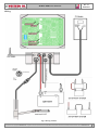
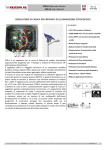
1
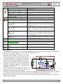
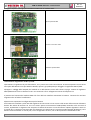
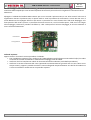
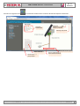
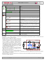
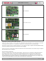
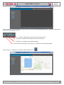
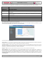
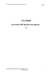
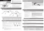
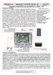
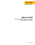
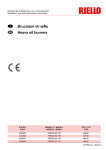
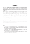
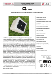
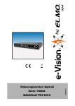
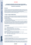
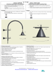
SPB-LS-GSM Manuale installazione
Rev. 1.3
09-04-2014
REGOLATORE DI CARICA PER IMPIANTI DI ILLUMINAZIONE FOTOVOLTAICI CON CONTROLLO
GSM
FEATURES:
• 12V / 24V tensione di batteria
• 225W/450W max PV per sistemi 12V/24V
• Carica MPPT con tensione del modulo fino
a 100V
• Diodo di blocco integrato
• Batterie Sealed or Flooded Lead Acid
• Compensazione in temperature della
tensione di carica
• Protezione di Low Battery
SPB-LS/GSM è un regolatore per la carica di batterie da modulo fotovoltaico
appositamente progettato per l’impiego in impianti di illuminazione offgrid (lampione fotovoltaico). Grazie al modem GSM integrato, il regolatore
SPB-LS/GSM può essere controllato da remoto attraverso l’applicazione
web residente sul server WesternCo. Almeno una volta al giorno il
regolatore apre una connessione GPRS verso il server WesternCo e scarica i
dati di funzionamento giornalieri. Sul server WesternCo è presente una
applicazione (WCloud) che permette all’utente di analizzare i dati raccolti
giornalmente dai propri lampioni durante il funzionamento, segnala
eventuali anomalie o malfunzionamenti del regolatore e per permette
all’utente di modificare le impostazioni di funzionamento del lampione
come il numero di ore di accensione per notte e la soglia di lowBattery. Più
avanti in questo manuale sarà spiegato meglio il funzionamento del sistema
di controllo remoto.
Il regolatore SPB-LS/GSM è alloggiato all’interno di un contenitore metallico
protetto all’acqua (grado IP66), quindi può essere installato direttamente
sul palo fotovoltaico senza dover aggiungere ulteriori protezioni.
Il circuito di carica dal modulo PV implementa un efficiente algoritmo di
ricerca del punto di massima potenza (MPPT), in grado di funzionare su un
esteso campo di tensioni; è ammessa una tensione massima sul modulo
fino a 100V. Il regolatore può caricare indifferentemente batterie al piombo
sia a 12V che a 24V; all’accensione l’SPB-LS/GSM riconosce
automaticamente se la batteria è a 12V o 24V e automaticamente regola le
soglie di ricarica. Il regolatore gestisce automaticamente l’accensione e lo
spegnimento della lampada; al crepuscolo (si rivela i crepuscolo quando la
tensione del modulo PV scende sotto la soglia Vnight) il regolatore accende
la lampada e la mantiene accesa per un numero di ore configurabili
dall’utente (l’impostazione di default è di 8 ore, ma è configurabile
dall’utente anche da remoto). Si possono anche impostare dei programmi
di accensione lampada che prevedono delle ore di funzionamento a
potenza ridotta (dimmer) in questo modo si può controllare in modo
accurato il consumo della lampada in modo che rientrino nei vincoli di
dimensionamento del sistema stad-alone.
• Protezione di Over-temperature
• Protezione di Overload
• Protezione inversione polarità batteria
• Controllo remote attraverso modem GSM
• Comanda l’accensione della lampada a
flusso pieno e a flusso ridotto
• IP66 per applicazioni all’esterno
This document is the property of WESTERN CO. Srl - All rights are reserved - Reproduction and use of information contained within this document is forbidden without the written consent of WESTERN CO. Srl
1
SPB-LS-GSM Manuale installazione
Rev. 1.3
09-04-2014
Wiring
Fig. 2 Wiring scheme
This document is the property of WESTERN CO. Srl - All rights are reserved - Reproduction and use of information contained within this document is forbidden without the written consent of WESTERN CO. Srl
2
SPB-LS-GSM Manuale installazione
Rev. 1.3
09-04-2014
Visualizzazioni e protezioni:
Led PV
Verde
Funzionalità
Il numero di lampeggi effettuati indica l’’intensità di corrente dal
modulo fotovoltaico.
1 flash con pausa di 4,3 sec.: 0,5A < PV current < 1,5A
2 flash con pausa di 4,3 sec.: 1,5A < PV current < 2,5A
e cosi via…
…valori intermedi…
13 flash con pausa di 4,3 sec.: 12,5A < PV current < 13,5A
Led Status Funzionalità
Rosso
Led 12/24 Funzionalità
Verde
Indica lo stato del sistema
Se sempre acceso indica un’anomalia del sistema che richiede un
reset.
1 flash ogni 2,2 secondi: protezione di Low-Battery attiva; carico
disattivato; occorre attendere che il modulo PV ricarichi la batteria
dopodiché la protezione si disattiva. (condizione di normale
funzionamento)
2 flash ogni 2,2 secondi: protezione di sovraccarico attiva; carico
disattivato; dopo circa due minuti si autoripristina esegue tre
tentativi in sequenza dopodiché aspetterà la notte successiva per
riprovare.
3 flash ogni 2,2 secondi: protezione di sovratemperatura; carico
disattivo e circuito di ricarica disattivato; occorre attendere che la
temperatura interna al contenitore diminuisca dopodiché la
protezione si disattiva.
4 flash ogni 2,2 secondi: protezione di sovratensione; circuito di
ricarica disattivato; la protezione si disattiverà quando la tensione
di batteria rientra nel range operativo.
Indica la tensione nominale di funzionamento del sistema
Led Load
giallo
Oltre all’indicazione della tensione nominale di funzionamento del
sistema, se ogni 4,3sec si spegne per un attimo indica che la sonda
NTC e disconnessa. La Vch equivale a quella per 60°C
Quando acceso indica che la lampada (load) è alimentata.
Led
Dimmer
giallo
Quando acceso indica che la lampada è in riduzione di flusso
Funzionamento:
L’ SPB-LS/GSM è un regolatore di carica da moduli fotovoltaici per batterie elettrochimiche al piombo di tipo ermetico
(SEAL) o ad acido libero (FLOOD). In fig. 1 è riportato uno schema di principio.
(1)-Circuito di ricarica: adatta la VPAN e la IPAN
(rispettivamente tensione e corrente del modulo
SPB-LS/GSM
1
fotovoltaico) in modo da ricercare la condizione in cui
IP AN
IBATT
MPPT
la potenza erogata dal modulo PV è massima,
realizzando quello che nella letteratura tecnica è
indicato con la sigla MPPT (Maximum Power Point
4
Tracking). Inoltre gestisce la ricarica della batteria
MICROCON TROL LER
VP AN
V BATT
V L OAD
riducendo la corrente erogata verso la batteria nelle
condizioni in cui la tensione VBATT supera la sua
D IMMER
3
2
tensione di ricarica (VCH).
(2)-Diodo di blocco: serve ad evitare che durante la
ILO AD
notte, quando il modulo fotovoltaico non è illuminato
Fig. 1 Schema di
questo possa assorbire corrente dalla batteria.
principio il programma impostato dall’utente, comanda
(3)-Circuito per il controllo del carico: accende o spegne il carico secondo
la segnalazione Dimmer, e provvede al distacco del carico in caso di batteria scarica o sovraccarico.
(4)-Microcontrollore: controlla l’intero circuito, misura le correnti e tensioni del modulo della batteria e del carico,
esegue l’algoritmo MPPT.
This document is the property of WESTERN CO. Srl - All rights are reserved - Reproduction and use of information contained within this document is forbidden without the written consent of WESTERN CO. Srl
3
SPB-LS-GSM Manuale installazione
Rev. 1.3
09-04-2014
Scelta del modulo fotovoltaico:
Il regolatore di carica SPB-LS/GSM, grazie al circuito di ricarica con MPPT, permette di impiegare una ampia gamma di
moduli fotovoltaici garantendo lo sfruttamento ottimale di tutta la potenza. Il modulo PV va scelto a seconda della
tensione nominale della batteria e rispettando i vincoli dell’ingresso pannello del SPB-LS/GSM: massima tensione a
circuito aperto: 100V e massima potenza di pannello 220W con batteria a 12V e 440W con batteria 24V.
Tensione
nominale
Caratteristiche moduli PV
batteria
Vmp: tensione alla massima potenza a T=25°C >
15,0V
VOC: tensione circuito aperto a T=-10°C <100V
IPAN
Tensione nominale
PMAX: massima potenza a 25°C < 225W
Consigliamo moduli al silicio mono o poly-cristallino con numero di celle da minimo 36 a massimo 144 celle.
batteria 12V
Vmp: tensione alla massima potenza a T=25°C >
VPAN 30,0V
VOC: tensione circuito aperto a T=-10°C <100V
Vmp VOC
Tensione nominale
PMAX: massima potenza a 25°C < 450W
batteria 24V
Consigliamo moduli al silicio mono o polycristallino con numero di celle da minimo 72 a
massimo 144 celle.
Configurazione modem GSM e installazione SIM
Per il corretto funzionamento del controllo remoto si deve installare all’interno del regolatore SPB-LS-GSM una sim
(dimensioni standard 15x25mm) GSM con due caratteristiche: 1. Abilitata ad effettuare connessioni GPRS (l’operatore
deve fornire l’impostazione dell’APN), 2. Abilitata a ricevere/inviare SMS. Non è necessario invece che la sim sia abilitata
a mandare e ricevere telefonate.
I’SPB-LS-GSM esegue giornalmente una connessione GPRS nella quale scambia con il server una quantità massima di
dati pari a 16Kbyte per un massimo volume di traffico al mese pari a 500Kbyte. Si consiglia di acquistare una sim card
che abbia una tariffa appropriata a questo volume di dati; ad esempio esistono operatori che presentano tariffe inferiori
a 1,00 € al mese per ogni Mbyte di traffico GPRS. Contattare la Western Co per consigli sulla scelta dell’operatore e della
tariffa appropriata al sistema. Perché il modem interno al regolatore SPB-LS-GSM funzioni correttamente è necessario
configurare l’APN (impostazione che deve essere fornita dall’operatore della SIM scelta) e deve essere eseguita in
fabbrica dalla WesternCo. Sarà necessario al momento dell’ordine del prodotto comunicare alla WesternCo il corretto
APN da impostare nel modem GSM. Qualora fosse necessario, la WesternCo è in gado di modificare da remoto,
mandando al modem GSM un opportuno SMS, l’impostazione dell’APN.
This document is the property of WESTERN CO. Srl - All rights are reserved - Reproduction and use of information contained within this document is forbidden without the written consent of WESTERN CO. Srl
4
SPB-LS-GSM Manuale installazione
Rev. 1.3
09-04-2014
Di seguito sequenza immagini per installazione SIM card nel modem GSM:
Aprire sportello SIM
Inserire la sim nella slitta
Chiudere sportello SIM
Installazione regolatore SPB-LS/GSM
1)Posizionare il regolatore sul palo fotovoltaico, con i pressa cavo rivolti verso il basso. Se avete acquistato una struttura
testa-palo della Western Co tipo WTP55 o WTP20, questa è già predisposta per alloggiare il regolatore SPB-LS/GSM.
2)Eseguire i cablaggi della lampada, del modulo PV e della batteria come nello schema a pag.2. Insieme al regolatore
SPB-LS/GSM sono forniti in dotazione tutti i cavi necessari a fare i collegamenti interni del lampione PV.
3) Posizionare l’antenna del modem GSM al di fuori del box metallico contenente le batterie. L’antenna ha una base
magnetica che ne facilita l’installazione.
4)Deve essere impostata la configurazione per le batterie.
Se la batteria è installata a più di 3mt dal regolatore di carica esso avrà un errore nella misura della tensione di batteria
dovuto alla caduta di tensione sui cavi. Per evitare questo inconveniente l’SPB-LS/GSM, basandosi sulla corrente di
ricarica, implementa un algoritmo che compensa la caduta di tensione sui cavi di batteria. Questo algoritmo è attivo se
lo switch No. 5 è settato in posizione OFF ed è disattivo se lo switch No 5 è in posizione ON (settaggio di fabbrica). Se la
batteria è stata installata in cima al palo, vicino al regolatore di carica, non si deve spostare lo switch No5 in OFF.
This document is the property of WESTERN CO. Srl - All rights are reserved - Reproduction and use of information contained within this document is forbidden without the written consent of WESTERN CO. Srl
5
SPB-LS-GSM Manuale installazione
Rev. 1.3
09-04-2014
Ulteriori settaggi, come la tensione di carica (Vch), la massima profondità di scarica della batteria (VLB) e le ore di
accensione della lampada per notte saranno impostate da remoto la prima volta che il regolatore si connette al server
Western Co.
5)Eseguire il collaudo del modem GSM. Premere per circa 1 secondo il pulsante TEST, e una volta acceso il led rosso di
segnalazione rilasciare il pulsante TEST; in questo modo si avvia la procedura di connessione e scarico dei dati verso il
server WesternCo che impiegare all’incirca 2/3 minuti. La procedura è in corso fintanto che il led verde lampeggia, ed è
finita quando il led verde è spento. La procedura ha avuto successo se, con il led verde spento, il led rosso non esegue
alcun lampeggio, viceversa la procedura ha fallito se, a led verde spento il led rosso lampeggia; in tal caso contattare il
centro assistenza WesternCo.
Pulsante TEST
Led segnalazione
Collaudo impianto:
Appena messo in funzione il sistema procedere al collaudo:
• Con il modulo PV esposto al sole, verificare che l’ SPB-LS/GSM ricarichi la batteria osservando il led(1) che indica
l’intensità di corrente dal modulo PV. Effettuerà dei lampeggi come da tabella.
• Verificare che il led 12V/24V non indichi la disconnessione della sonda NTC (vedi tabella precedente).
• Verificare la corretta accensione del carico (spostando momentaneamente gli switch 4-5-6-7 tutti a OFF: carico
sempre acceso); oppure è possibile simulare la notte scollegando temporaneamente uno dei fili del modulo PV
o ancora oscurando il modulo PV con un pannello coprente.
This document is the property of WESTERN CO. Srl - All rights are reserved - Reproduction and use of information contained within this document is forbidden without the written consent of WESTERN CO. Srl
6
SPB-LS-GSM Manuale installazione
Rev. 1.3
09-04-2014
Controllo remoto del lampione PV
Ogni giorno il regolatore di carica SPB-LS/GSM si connette al server WesternCo e scarica i dati che ha raccolto durante il
suo funzionamento. L’utente può accedere attraverso l’applicazione WCloud ai dati del sistema attraverso il seguente
indirizzo internet:
http://www.western.it/wcloud/login.php
La WesternCo fornirà insieme al prodotto SPB-LS/GSM username e password per accesso all’applicazione WCloud.
Dopo l’accesso nella parte sinistra dello schermo sono elencati tutti i regolatori SPB-LS/GSM acquistati. Ogni regolatore
è rappresentato dalla seguente sequenza di icone:
This document is the property of WESTERN CO. Srl - All rights are reserved - Reproduction and use of information contained within this document is forbidden without the written consent of WESTERN CO. Srl
7
Rev. 1.3
09-04-2014
SPB-LS-GSM Manuale installazione
Visualizza in forma di grafico i dati del lampione
Visualizza in forma numerica i dati del lampione
Permette di configurare i dettagli relativi all’installazione
Numero seriale identificativo del lampione. E’ stampato sulla contenitore del regolatore
SPB-LS/GSM
La prima operazione da eseguire è configurare i dati relativi all’installazione attraverso l’icona
.
L’utente deve definire i dati relativi all’installazione; lo scopo di questi dati è quello di aiutare l’utente a identificare in
modo chiaro il lampione e la sua configurazione. Di seguito una spiegazione dettagliata dei campi da compilare:
System ID
Serial
Phone number
Installation city
Street
Serial Street
Geo Coordinates
Pv module
PV lamp
Battery
Battery capacity
Installation data
Program Timer
Numero Identificativo dell’SPB-LS/GSM stampato sul prodotto. Non può essere modificato.
Numero di serie del modem GSM interno al SPB-LS/GSM. Non può essere modificato.
Numero di telefono associato alla SIM.
Città di installazione del sistema.
Strada di installazione.
L’utente può inserire un numero che definisce l’ordine con cui vengono visualizzati i sistemi appartenenti
alla stessa strada.
Coordinate geografiche del luogo di installazione. Per settare questo parametro, individuare il luogo di
installazione all’interno della cartografia presente nella pagina e cliccare nel punto di installazione;
automaticamente verrà riempito il campo ‘Geo Coordinates’.
Indicare marca modello e potenza del modulo PV.
Indicare marca modello e potenza della lampada installata.
Indicare marca e modello della batteria installata.
Indicare la capacità della batteria in Ah.
Indicare la data di installazione.
Selezionare quali ore dal crepuscolo il lampione deve essere acceso o in ridotta
Premere il tasto UPDATE per memorizzare il campi inseriti.
This document is the property of WESTERN CO. Srl - All rights are reserved - Reproduction and use of information contained within this document is forbidden without the written consent of WESTERN CO. Srl
8
Rev. 1.3
09-04-2014
SPB-LS-GSM Manuale installazione
Una volta inseriti i campi relativi ad ogni singolo lampione, questi compariranno ordinati per città di installazione e per
via mentre la cartografia mostra dove il sistema è stato installato.
Per ogni lampione si può impostare:
Charge voltage (Vch): è la massima tensione di batteria ammessa nella fase di ricarica. Questo parametro varia in
funzione della temperatura di batteria come nel grafico N1. Il valore indicato nella precedente figura è inteso a 25°C.
Low battery voltage (Vlb): Quando la tensione di batteria scende sotto la soglia Vlb il regolatore SPB-LS/GSM disconnette
la lampada in modo da proteggere la batteria da scariche profonde. Il sistema esce dalla protezione di low battery
automaticamente quando la tensione di batteria sale sopra la soglia Vch – 0.24V (per sistemi a 12V) e Vch – 0.48V (per
sistemi a 24V ).
ProgTimer – hours: Per ciascuna ora dal tramonto all’alba si può impostare la lampada accesa alla massima luminosità,
accesa ad una luminosità intermedia oppure spenta.
Self-management: Quando l’impostazione self-management è in ON il regolatore SPB-LS/GSM sceglie in modo
automatico l’impostazione ProgTimer. Un algoritmo proprietario della Western Co, basato sull’energia prodotta
giornalmente dal modulo PV, setta il ProgTimer in modo da usare tutta l’energia giornaliera prodotta dal modulo PV
riducendo il rischio che il sistema vada in protezione di low battery. L’algoritmo self-management imposta 12 ore di
accensione lampada ma incrementa o decrementa il numero di ore in riduzione di flusso come nella seguente tabella:
Alla prima attivazione del Self-management,
l’SPB-LS/GSM seta il ProgTimer:
Se il sistema incontra alcuni giorni di bel tempo
allora questo incrementa il numero di ore di
accensione alla massima luminosità.
dopo 1 day
dopo 2 days
dopo 3 days
…..
Se il sistema incontra alcuni giorno di cattivo
tempo questo decrementa le ore alla massima
lumiosità.
after 1 day
after 2 days
after 3 days
…
Minimum
This document is the property of WESTERN CO. Srl - All rights are reserved - Reproduction and use of information contained within this document is forbidden without the written consent of WESTERN CO. Srl
9
Rev. 1.3
09-04-2014
SPB-LS-GSM Manuale installazione
Attraverso la seguente icona
si accede alla visualizzazione numerica dei dati del lampione selezionato.
Stato interno
dell’SPB-LS/GSM
Informazione
sulla
quantità di dati scambiati
nell’ultima sessioe GPRS
Informazioni sulla quantità
di energia prodotta o
consumata dal sistema
Permette di muoversi
attaverso I blocchi di dati
ricevuti
Permette di selezionare il giorno
Data e ora relativa al blocco di
dati correntemente visualizzato
Permette di spostarsi al
giorno precedente
This document is the property of WESTERN CO. Srl - All rights are reserved - Reproduction and use of information contained within this document is forbidden without the written consent of WESTERN CO. Srl
1
0
SPB-LS-GSM Manuale installazione
Attraverso la seguente icona
Rev. 1.3
09-04-2014
si accede alla visualizzazione sotto forma di grafici del lampione selezionato.
Nella legenda è possible
attivare/disattivare
la
visualizzazione di ciascuna
linea del grafico
Informazioni sulla quantita
di energia prodotta o
consumata dal sistema
Setta la data relative al giorno
correntemente visualizzato
Sposta al giorno
precedente o
successivo
This document is the property of WESTERN CO. Srl - All rights are reserved - Reproduction and use of information contained within this document is forbidden without the written consent of WESTERN CO. Srl
1
1
SPB-LS-GSM Manuale installazione
Rev. 1.3
09-04-2014
Dimensioni
This document is the property of WESTERN CO. Srl - All rights are reserved - Reproduction and use of information contained within this document is forbidden without the written consent of WESTERN CO. Srl
1
2
Rev. 1.3
09-04-2014
SPB-LS-GSM Manuale installazione
Grafico 1
Grafico 2
SPECIFICHE TECNICHE
Tensione di batteria
Tensione di pannello a circuito aperto
Corrente di pannello
Massima potenza di pannello
Tensione uscita carico
Corrente del carico
Tensione di ricarica a 25°C
SEAL
FLOOD
Compensazione della Vch in funzione della
temperatura di batteria (Tbatt) (vedi Grafico 1)
Tensione di Low battery SW_5->ON (impostabile)
Compensazione della Vch con SW_5->OFF
(vedi Grafico 2)
Tensione uscita Low battery a 25°C
Compensaione della Vlb con SW_5->OFF
(vedi Grafico 2)
Tensione rilevazione giorno
Tensione rilevazione notte: Vnight = Vday –0.8V
Auto consumo
Temperatura ambiente di esercizio
Grado di protezione
Peso
Dimensioni scatola (mm)
Ingombro con cavi (mm)
Vbatt
Vpan
Ipan
Pmax
Vload
Iload
Vch
Vtadj
Tensione nominale batteria
12V
Min
Typ
Max
10V
12V
17V
20V
100V
13,5A
225W
Vbatt
8A
-
14.44V
14.88V
24mV/°C
Tensione nominale batteria
24V
Min
Typ
Max
20V
24V
34V
40V
100V
13,5A
450W
Vbatt
8A
-
-
28.88V
29.76V
48mV/°C
-
Vlb
Vremch
11.2V
+58mV/A
12.4V
22.4V
+58mV/A
24.8V
Vout_lb
Vremlb
-
Vch-0,24V
-58mV/A
-
-
Vch-0,48V
-58mV/A
-
Vday
Vnight
Iqsc
Tamb
-
6.9V
4.8V
12.7mA
-
-
11.36V
8.96V
17,7mA
-
50°C
-10°C
160x135 H65
160x170 H65
-
-10°C
-
IP66
1.3Kg
50°C
IP66
1.3Kg
-
This document is the property of WESTERN CO. Srl - All rights are reserved - Reproduction and use of information contained within this document is forbidden without the written consent of WESTERN CO. Srl
1
3
SPB-LS-GSM Manuale installazione
Rev. 1.3
09-04-2014
Garanzia di legge
Western Co srl garantisce la buona qualità e la buona costruzione dei Prodotti obbligandosi, durante il periodo di
garanzia di 5 (cinque) anni, a riparare o sostituire a sua sola discrezione, gratuitamente, quelle parti che, per cattiva
qualità del materiale o per difetto di lavorazione si dimostrassero difettose.
Il prodotto difettoso dovrà essere rispedito alla Western Co srl o a società delegata dalla Western Co srl a fare assistenza
sul prodotto, a spese del cliente, assieme ad una copia della fattura di vendita, sia per la riparazione che la sostituzione
garantita. I costi di re-installazione del materiale saranno a carico del cliente.
La Western Co srl sosterrà le spese di re spedizione del prodotto riparato o sostituito.
La garanzia non copre i Prodotti che, in base a nostra discrezione, risultino difettosi a causa di naturale logoramento,
che presentino guasti causati da imperizia o negligenza del cliente, da imperfetta installazione, da manomissioni o
interventi diversi dalle istruzioni da noi fornite .
La garanzia decade altresì in caso di danni derivanti da:
-trasporto e/o cattiva conservazione del prodotto.
-causa di forza maggiore o eventi catastrofici (gelo per temperature inferiori a -20°C, incendio, inondazioni, fulmini, atti
vandalici, ecc…).
Tutte le sopraccitate garanzie sono il solo ed esclusivo accordo che soprassiede ogni altra
proposta o accordo verbale o scritto e ogni altra comunicazione fatta tra il produttore e l’acquirente in rispetto
a quanto sopra.
Per qualsiasi controversia il Foro competente è Ascoli Piceno.
Smaltimento dei rifiuti
La Western Co in qualità di produttore del dispositivo elettrico descritto nel presente
manuale, ed in conformità al D.L 25/07/05 n 151, informa l’acquirente che questo
prodotto, una volta dismesso, deve essere consegnato ad un centro di raccolta
autorizzato oppure, in caso di acquisto di apparecchiatura equivalente può essere
riconsegnato a titolo gratuito al distributore della apparecchiatura nuova.
Le sanzioni per chi abusivamente si libera di un rifiuto elettronico saranno applicate
dalle singole amministrazioni comunali.
MADE IN ITALY
Western Co. s.r.l.
Via Pasubio, 1
San Benedetto del Tronto (AP)
63074 - Italy
[email protected]
www.western.it
This document is the property of WESTERN CO. Srl - All rights are reserved - Reproduction and use of information contained within this document is forbidden without the written consent of WESTERN CO. Srl
1
4
Rev. 1.3
09-04-2014
SPB-LS-GSM User Manual
CHARGE REGULATOR FOR PV LIGHTING SYSTEMS WITH GSM CONTROL
FEATURES:
• 12V / 24V battery voltage system
• 225W/450W max PV power for 12V/24V
systems
• MPPT charge with module voltage up to
100V
• Integrated blocking diode
• Sealed or Flooded Lead Acid Battery
• Temperature compensation of charge
voltage
SPB-LS/GSM is a charge regulator for the charge of batteries from PV
module; it has been specially designed for the use in off-grid PV lighting
systems for (PV street-lamp). Thanks to the integrated GSM modem, the
charge controller SPB-LS/GSM can be controlled remotely through a web
application residing on Western Co. server. At least once a day the
regulator opens a GPRS connection to Western Co. server and it downloads
the daily operating data. On Western Co. server there is an application
(WCloud) that allows the user to analyze the data collected every day from
their PV street-lamp during its working; it indicates eventual malfunctions
or failures of the regulator and it allows the user to modify the settings of
the PV street-lamp such as the number of hours of lamp activation per
night and Low Battery threshold. Later in this manual, we will explain better
the working of the remote control system.
The charge controller code SPB-LS/GSM is housed inside a metal box that is
protected from water (IP66 degree); therefore it can be installed directly on
the PV pole without having to add additional protections.
The charge circuit from PV module has got an efficient algorithm for the
search of the maximum power point (MPPT) that is Capable of operating
over an extended field of voltages. It is allowed a maximum voltage on the
PV module up to 100V. The regulator can charge either 12V PB batteries or
24V Pb batteries. On power ON, SPB-LS/GSM automatically recognizes if the
battery is at 12V or 24V and it automatically adjusts the charge thresholds.
The regulator automatically manages the power on and off of the lamp.
At dusk (when the voltage of the PV module drops below the Vnight
threshold) the charge controller switches on the lamp and keeps it on for a
number of hours that can be set by the user (the default setting is 8 hours,
but it can be set by the user even from remote position). You can also set
some programs for lamp’s power on with working hours with reduced flux
(dimmer). In this way you can check accurately the lamp consumption so to
remain inside the dimensioning of the PV off-grid system.
• Low Battery Protection
• Over-temperature Protection
• Overload Protection
• Battery polarity reversion protection
• Remote control by GSM modem
• Lamp power on at full flux and reduced
flux
• Light sensor from PV module
• IP66 for Outdoor Applications
This document is the property of WESTERN CO. Srl - All rights are reserved - Reproduction and use of information contained within this document is forbidden without the written consent of WESTERN CO. Srl
1
5
SPB-LS-GSM User Manual
Rev. 1.3
09-04-2014
Wiring
Fig. 2 Wiring scheme
This document is the property of WESTERN CO. Srl - All rights are reserved - Reproduction and use of information contained within this document is forbidden without the written consent of WESTERN CO. Srl
1
6
SPB-LS-GSM User Manual
Rev. 1.3
09-04-2014
Displaying and Protections:
PV LED:
Green
Functionality
The number of flashes indicates the intensity of current from the PV
module
1 flash with a pause of 4,3 sec.: 0,5A < PV current < 1,5A
2 flashes with a pause of 4,3 sec.: 1,5A < PV current < 2,5A
and so on…
…intermediate values…
13 flashes with a pause of 4,3 sec.: 12,5A < PV current < 13,5A
Status
LED:
Red
Functionality
It indicates the system status
If always ON it indicates a system anomaly – a reset is needed
LED 12/24 Functionality
Green
Led Load
Led
Dimmer
Yellow
Yellow
1 flash every 2,2 seconds: the Low-Battery protection is ON; the
load is deactivated; you have to wait that the PV module recharges
the battery and, after that, the protection deactivates (condition of
normal working).
2 flashes every 2,2 seconds: the Overload protection is ON; the load
is deactivated; after about 2 minutes the load is resetting; it makes
3 attempts in sequence; then it will wait the following night to try
again.
3 flashes every 2,2 seconds: Over-temperature protection; load
OFF and deactivated charge circuit; wait that the temperature
inside the box decreases <<<<<<<<<<<, then the protection will
deactivate.
4 flashes every 2,2 seconds: Overvoltage protection; the charge
circuit is deactivated; the protection will deactivate when the
battery voltage goes back within its operative range.
It indicates the working nominal voltage of the system
In addition to the working nominal voltage of the system, if every
4,3sec it switches off for a moment, this means that the NTC probe
is disconnected. Vch is equivalent to that for 60°C.
When this led is ON, the lamp (LOAD) was been power supplied.
When this led is ON, the lamp (LOAD) was been power supplied,
but in low flux (DIMMER).
Working:
SPB-LS/GSM is a PV charge controller for either Pb electrochemical sealed batteries (SEAL) or flooded lead acid
(FLOOD). Fig. 1 shows a principle diagram.
(1)-Charge circuit: it adapts VPAN and IPAN (respectively
voltage and current of the PV module) in order to
SPB-LS/GSM
1
search the condition in which the power delivered by
IP AN
IBATT
MPPT
the PV module is maximum, realizing what is
indicated in the technical literature with the acronym
MPPT (Maximum Power Point Tracking). In addition,
4
it manages the battery charge by reducing the
MICROCON TROL LER
VP AN
V BATT
V L OAD
current delivered to the battery when VBATT voltage
exceeds its charging voltage (VCH).
D IMMER
3
2
(2)-Blocking diode: it is needed to avoid that during the
night, when the PV module is not lighted, this can
ILO AD
Fig. 2 Principle diagram
absorb current from the battery.
(3)-Circuit for the load control: it switches ON/OFF the
load according to the program set by the user, it commands the “Dimmer” signaling and it disconnects the load in
case of low battery or overload.
(4)-Microcontroller: it controls the whole circuit, it measures currents and voltages of PV module, battery and load,
it performs the MPPT algorithm.
This document is the property of WESTERN CO. Srl - All rights are reserved - Reproduction and use of information contained within this document is forbidden without the written consent of WESTERN CO. Srl
1
7
SPB-LS-GSM User Manual
Rev. 1.3
09-04-2014
Choice of PV module:
SPB-LS/GSM charge controller, thanks to MPPT charge, allows to use a wide range of PV modules thus ensuring the
optimum exploitation of the power. The PV module has to be chosen according to the battery nominal voltage and
respecting the constraints of SPB-LS/GSM panel input: max open circuit voltage: 100V and max PV panel power: 225W
with 12V battery and 450W with 24V battery.
Battery nominal voltage
PV modules features
Vmp: voltage at maximum power at T=25°C >
15,0V
VOC: open circuit voltage at T=-10°C <100V
IPAN
12V battery nominal
PMAX: maximum power at 25°C < 225W
voltage
We recommend silicon modules mono or poly-crystalline with a
minimum number of 36 cells to a maximum of 144 cells.
VPAN Vmp: voltage at maximum power at T=25°C >
Vmp VOC
24V battery nominal
voltage
30,0V
VOC: open circuit voltage at T=-10°C <100V
PMAX: maximum power at 25°C < 450W
We recommend silicon modules mono or poly-crystalline with a
minimum number of 72 cells to a maximum of 144 cells.
Configuration of GSM modem and SIM installation
For a correct working of the remote control, you have to install inside the SPB-LS/GSM charge controller a GSM sim
(standard dimension 15x25mm) with two features: 1. It has to be enabled to effect GPRS connections (the operator
must provide the APN setting), 2. It has to be enabled to receive/send SMS. It is not required that the sim is enabled to
send and receive phone calls.
SPB-LS/GSM performs daily a GPRS connection in which it exchanges with the server a maximum amount of data equal
to 16Kbyte for a maximum volume of traffic per month equal to 500Kbyte. We recommend to buy a sim card that has a
tariff appropriate to this volume of data; example, there are operators who have lower rates of 1.00 € per month for
each MB of GPRS traffic. Contact Western Co. for advice on the selection of operator and tariff appropriate to the
system. For a proper working of the modem inside the SPB-LS/GSM you must configure the APN (setting that must be
provided by your SIM provider) and this has to be executed at the factory by Western Co. When ordering, please
communicate to Western Co. the right APN to set in the GSM modem. If necessary, Western Co. is able to modify by
remote the APN setting by sending to the GSM modem a proper SMS.
This document is the property of WESTERN CO. Srl - All rights are reserved - Reproduction and use of information contained within this document is forbidden without the written consent of WESTERN CO. Srl
1
8
SPB-LS-GSM User Manual
Rev. 1.3
09-04-2014
Here below the image sequence for the installation of the SIM card in the GSM modem:
Open the SIM door
Insert the SIM in the slot
Close the SIM door
Installation of SPB-LS/GSM charge controller
1)Place the charge controller on the PV pole, with cable-glands facing downwards. If you purchased a top-of-pole
mounting structure by Western Co. code WTP55 or WTP20, this is already prepared to house SPB-LS/GSM.
2)Execute the wiring of lamp, PV module and battery as in the diagram on page 2. Together with SPB-LS/GSM we supply
all necessary cables to make the internal connections of PV streetlight.
3)Place the antenna of GSM modem outside the metallic box that contains batteries. The antenna has got a magnetic
base that makes easier its installation.
4)Set the batteries configuration.
If battery is installed at more of 3mt from charge regulator, it will have an error in the battery voltage measure due to
drop voltage in battery cables. To overcame this, the SPB-LS/GSM implements an algorithm that compensate the
battery voltage drop in the battery cables that use battery charging current. This algorithm is actives if switch No. 5 is
set in OFF position and is not active if switch No. 5 is in ON position (factory setting). If the battery has installed on top
of pole, near the charge regulator, you don’t need to move switch No. 5 in OFF position.
This document is the property of WESTERN CO. Srl - All rights are reserved - Reproduction and use of information contained within this document is forbidden without the written consent of WESTERN CO. Srl
1
9
SPB-LS-GSM User Manual
Rev. 1.3
09-04-2014
Further setting, like charge voltage (Vch), the maximum depth of battery discharge (VLB) and the number of lamp
ignitions for night will be set by remote control the first time the SPB-LS/GSM is connected to Western Co web server.
5) Make a test of the GSM modem. Press for about 1 second the TEST button and, once the signaling red LED is ON
release the TEST button; in this way you start the connection and procedure to uploading data towards the Western Co.
Server. The procedure need at lasts about 2/3 minutes. The procedure is in progress until the green LED flashes, and it is
ended when the green LED is off. The procedure was successful if, with the green LED off, the red LED does not flashes;
on the contrary the procedure failed if, with the green LED on, the red LED flashes. In this case, contact the service
center of Western Co.
TEST button
Signalling LED
System testing:
Once you put in function the system, make the testing:
• With the PV module exposed to sunrays, verify that SPB-LS/GSM charges the battery by observing the LED(1)
that indicates the intensity of current from the PV module. It will flash as described in the table.
• Verify that the 12V/24V LED does not indicate the disconnection of the NTC probe (see table above).
• Check the correct activation of the load (moving temporarily all switches 4-5-6-7 to OFF position: load always
on); otherwise you can simulate the night either by disconnecting temporarily one of the wires of the PV
module or obscuring the PV module with a covering panel.
Remote control of PV street-lamp
Everyday SPB-LS/GSM connects to Western Co. server and download the data collected during its working. The user can
access through WCloud application to the system data through the following internet address:
http://www.western.it/wcloud/login.php
Together with SPB-LS/GSM, Western Co. will supply username and password to access the WCloud application.
This document is the property of WESTERN CO. Srl - All rights are reserved - Reproduction and use of information contained within this document is forbidden without the written consent of WESTERN CO. Srl
2
0
SPB-LS-GSM User Manual
Rev. 1.3
09-04-2014
After the access, in the left side of the screen there is a list of all purchased SPB-LS/GSM. Each regulator is represented
by the following sequence of icons:
It shows in graphical form the data of the PV street-lamp
It shows in numerical form the data of the PV street-lamp
It allows you to configure the installation details
Serial number identifying the street-lamp. It is printed on the box of SPB-LS/GSM
The first step is to configure the installation data through the icon
.
This document is the property of WESTERN CO. Srl - All rights are reserved - Reproduction and use of information contained within this document is forbidden without the written consent of WESTERN CO. Srl
2
1
SPB-LS-GSM User Manual
Rev. 1.3
09-04-2014
The user must define the data relative to installation; The purpose of these data is to help the user to clearly identify the
street-lamp and its own configuration. Here below you can see a detailed explanation of the fields to be filled:
System ID
Serial
Phone number
Installation city
Street
Serial Street
Geo Coordinates
Pv module
PV lamp
Battery
Battery capacity
Installation data
Program Timer
Identification Number of SPB-LS/GSM printed on the product. It cannot be changed.
Serial number of GSM modem internal to SPB-LS/GSM. It cannot be changed.
Telephone number associated with the SIM.
City of system installation.
Street/road of installation.
The user can enter a number that establishes the order with which the systems belonging to the same road
are displayed.
Geographic coordinates of the place of installation. To set this parameter, identify the place of installation
within the cartography on the page and click on the installation point; automatically the ‘Geo Coordinates’
field will be filled.
Indicate brand, model and power of PV module.
Indicate brand, model and power of the installed lamp.
Indicate brand and model of the installed battery.
Indicate the battery capacity in Ah.
Indicate the date of installation.
Select which hours from sunset the LED lamp must be activated with full flux or reduced flux.
Press UPDATE button to memorize the inserted fields.
Once you entered the fields concerning each PV street-lamp, these ones will appear ordered by installation city and
street while the cartography shows where the system was installed.
For each PV street-lamp you can set:
Charge voltage (Vch): Is the maximum allowed battery voltage in charge state. This parameter depends to the battery’s temperature
as in graph 1. The value indicated in last figure is understood at 25°C battery’s temperature.
Low battery voltage (Vlb): When battery voltage drops below the threshold Vlb the SPBL-LS/GSM disconnects the lamp to protect
battery from deep discharge. The system exits from the low battery protection automatically when battery voltage rises above the
threshold Vch – 0.24V (for 12V systems) and Vch – 0.48V (for 24V systems).
ProgTimer – hours: for each hour from sunset to sunrise you can set on, set on in low flux or set off the lamp.
Self-management: when self-management is in ON, the SPB-LS/GSM chooses the most suitable timer. A Western Co
proprietary algorithm, based on the daily energy produced by the PV module, it sets the ProgTimer in order to use all
the daily energy produced by the module without the risk that the system goes into low battery protection. The selfmanagement algorithm sets the lamp on for 12 hours but can increase or decrease the number of hours at low flow as
in following table.
This document is the property of WESTERN CO. Srl - All rights are reserved - Reproduction and use of information contained within this document is forbidden without the written consent of WESTERN CO. Srl
2
2
Rev. 1.3
09-04-2014
SPB-LS-GSM User Manual
At the activation of Self-management, SPBLS/GSM sets ProgTimer:
If the system detects a few days of good weather
it increases the hours at maximum flux..
after 1 day
after 2 days
after 3 days
…..
Maximum
If the system detects a few days of bad weather
it decreases the hours at maximum flux..
after 1 day
after 2 days
after 3 days
…
Minimum
Through the following icon
you go to the numeric display of data of the selected PV street-lamp.
internal state of
the controller
Information on the amount
of data exchanged in the
last GPRS session
Information on the amount
of energy produced or
consumed in the system
Move through the blocks of
date received
Select the day
Data and time relative to the
block of date current displayed
Move to the previous day
This document is the property of WESTERN CO. Srl - All rights are reserved - Reproduction and use of information contained within this document is forbidden without the written consent of WESTERN CO. Srl
2
3
Rev. 1.3
09-04-2014
SPB-LS-GSM User Manual
Through the following icon
you go to the display in the form of graphs of the selected PV street-lamp.
The
legend
can
enable / disable each
line in the graph
Information on the amount
of energy produced or
consumed in the system
Set data relative to the daily
date current displayed
moves to the
previous/next
day
This document is the property of WESTERN CO. Srl - All rights are reserved - Reproduction and use of information contained within this document is forbidden without the written consent of WESTERN CO. Srl
2
4
SPB-LS-GSM User Manual
Rev. 1.3
09-04-2014
Dimensions
This document is the property of WESTERN CO. Srl - All rights are reserved - Reproduction and use of information contained within this document is forbidden without the written consent of WESTERN CO. Srl
2
5
Rev. 1.3
09-04-2014
SPB-LS-GSM User Manual
Graph 1
Graph 2
TECHNICAL FEATURES
Battery voltage
Open circuit voltage
Panel current
Max panel power
Load output voltage
Load current
Charge voltage at 25°C
SEAL
FLOOD
Vch compensation according to battery temperature
(Tbatt) (see Graph 1)
Low battery voltage @Iload=0 (settable)
Vch compensation with SW_5->OFF (see Graph 2)
Low battery output voltage at 25°C
Vlb compensation with SW_5->OFF (see Graph 2)
Voltage of day detection
Voltage of night detection: Vnight = Vday –0.8V
Self-consumption
Ambient temperature
IP Protection degree
Weight
Box dimensions (mm)
Dimensions with cables (mm)
Vbatt
Vpan
Ipan
Pmax
Vload
Iload
Vch
Vtadj
Vlb
Vremch
Vout_lb
Vremlb
Vday
Vnight
Iqsc
Tamb
12V battery nominal voltage
Min
Typ
Max
10V
12V
17V
20V
100V
13,5A
225W
Vbatt
8A
14.1V
15.2V
14.44V
14.88V
24mV/°C
-
24V battery nominal voltage
Min
Typ
Max
20V
24V
34V
40V
100V
13,5A
450W
Vbatt
8A
28.2V
30.4V
28.88V
29.76V
48mV/°C
-
11.2V
22.4V
-
12.4V
+58mV/A
Vch-0,24V
58mV/A
6.9V
4.8V
12.7mA
-10°C
-
IP66
1.3Kg
-
-
-
-
50°C
-10°C
160x135 H65
160x170 H65
-
24.8V
+58mV/A
Vch-0,48V
-58mV/A
11.36V
8.96V
17,7mA
50°C
IP66
1.3Kg
-
This document is the property of WESTERN CO. Srl - All rights are reserved - Reproduction and use of information contained within this document is forbidden without the written consent of WESTERN CO. Srl
2
6
SPB-LS-GSM User Manual
Rev. 1.3
09-04-2014
Warranty
Western Co. Srl guarantees the good quality and good design of its own Products obliging itself, during the warranty
period of 5 (five) years, to repair or replace at its sole discretion, for free, those defective parts owing to poor quality of
material or defect in workmanship.
The defective product must be returned to Western Co. Srl or to the company delegated by Western Co to make
product support, at customer’s expenses, together with a copy of the invoice both for repairing and warranty
replacement. The costs of re-installation of the equipment will be borne by the customer.
Western Co. srl will bear the transport expenses of the repaired or replaced product.
The warranty does not cover Products that, according to our discretion, are defective due to natural wear, showing
damages caused by incompetence or negligence of the customer, imperfect installation, by tampering or other
interventions different by the instructions supplied by us. The warranty is not valid also in case of damages coming
from:
- transport and/or incorrect storage of the product.
- force majeure or catastrophic events (frost to temperatures below -20 ° C, fire, flood, lightning, vandalism, and so on).
All of the abovementioned guarantees are the sole and exclusive agreement which supersedes any proposal or
agreement, oral or written, and any other communication made between the manufacturer and the purchaser in
respect of the above.
For any dispute the jurisdiction is Ascoli Piceno.
Waste disposal
Western Co. as manufacturer of the electrical device herein described and in accordance
with DL 07/25/2005 n 151, informs the consumer that this product, once abandoned,
must be delivered to an authorized collection center or, in case of purchase of an
equivalent equipment, it can be returned free of charge to the distributor of the new
equipment. The penalties will be applied by individual Municipalities.
MADE IN ITALY
Western Co. s.r.l.
Via Pasubio, 1
San Benedetto del Tronto (AP)
63074 - Italy
[email protected]
www.western.it
This document is the property of WESTERN CO. Srl - All rights are reserved - Reproduction and use of information contained within this document is forbidden without the written consent of WESTERN CO. Srl
2
7