1
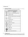
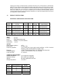
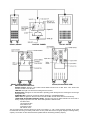
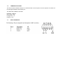
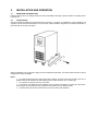
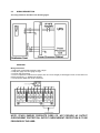
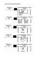
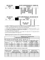
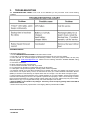
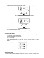
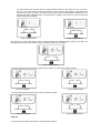
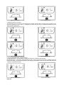
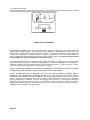
UniStar II
SG0603
SG1003
SG0604
SG1004
10100 Royalton Rd.
Cleveland, OH 44133 USA
Voice: (440) 237-3200 • Fax: (440) 237-1744
Internet: http://instserv.com
User’s Manual
TABLE OF CONTENTS
1. INTRODUCTION 1
1.1 Explanation of symbols……………………………………………………………………………...1
1.2 System description ………………………………………………………………………………….1
1.3 Product specification ………………………………………………………………………………..2
Electrical specifications ……………………………………………………………………….2
Operating environment ………………………………………………………………………..2
Mechanical specification ………………………………………………………………………2
1.4 Switches and displays ………………………………………………………………………………3
1.5 Safety …………………………………………………………………………………………………4
1.6 Communication port …………………………………………………………………………………6
1.7 RS232 interface ……………………………………………………………………………………...6
2. INSTALLATION AND OPERATION ………………………………………………………………………...7
2.1 Unpacking and inspection …………………………………………………………………………7
2.2 Installation …………………………………………………………………………………………..7
2.3 Wiring description ………………………………………………………………………………….8-10
3. TROUBLESHOOTING ……………………………………………………………………………………….11
APPLICATION NOTES …………………………………………………………………………………………A1
1. START UP …………………………………………………………………………………………………….A1
2. OUTPUT VOLTAGE SETTING …………………………………………………………………………….A2
3. DISPLAYS AND ALARMS …………………………………………………………………………………A2
1. Load level and battery capacity ……………………………………………………………………A2
2. Alarm for inverter short-circuiting and output over voltage ……………………………………..A2
3. Alarm for bus over-voltage …………………………………………………………………………A2
4. Alarm for over-temperature ………………………………………………………………………..A3
5. Display and alarm for overload ……………………………………………………………………A3
6. Alarm for BATTERY WEAK or BATTERY BAD …………………………………………………A3
7. Alarm for abnormal input voltage …………………………………………………………………A4
8. Battery over-voltage alarm …………………………………………………………………………A4
9. Bypass S.T.S short alarm ………………………………………………………………………….A4
10. Inverter S.T.S short alarm ………………………………………………………………………..A5
4. LIMITED PRODUCT WARRANTY ………………………………………………………………………………………A5
1. INTRODUCTION
1.1
EXPLANATION OF SYMBOLS
Some or all of the following symbols may be used in this manual or may appear on your unit. Please take a
moment to familiarize yourself with these symbols and their associated meanings.
1.2
SYSTEM DESCRIPTION
The SG SERIES UPS is an advanced true on-line sine wave uninterruptible power system with automatic
bypass. It provides reliable, regulated, transient-free AC power to your sensitive equipment, ranging from
computers and telecommunication systems to computerized instruments. Because the UPS is in the on-line
topology type of design, conditioned power is provided continuously to its connected devices. Unlike standby
UPS’s, its on-line structure always regulates and filters output power when commercial power is present.
During line power failure, the unit employs its internal maintenance-free battery to supply back-up power
without any transfer time. In the event of an overload or inverter failure, the UPS will transfer to bypass
mode as an alternate source. The UPS can transfer back to the inverter mode automatically after the
overload condition has been cleared. All transfers noted above occur with zero transfer time that can ensure
your equipment’s continuous operation.
1.3
PRODUCT SPECIFICATIONS
ELECTRICAL & MECHANICAL SPECIFICATIONS
Output
Current
MODEL
SG0603
28.8/27.3/26/25A
50,25/25,28.8
25/28.8,25,25/25A
SG0604
SG1003
SG1004
48.1/45.5/43.5/41.7A
83.3,41.7/41.7,48
41.7/48,41.7,41.7/41.7A
INPUT
Voltage:
Phase:
Frequency:
Power factor:
RATING
6KVA
4.2KW
6KVA
4.2KW
10KVA
7KW
10KVA
7KW
Hz
50/60
Hz
50/60
Hz
50/60
Hz
50/60
Hz
Input
Voltage
170-276
VAC
170-276
VAC
170-276
VAC
170-276
VAC
Output Voltage
208/220/230/240V
120, 120/120, 208,
120/208,240,120/240V
208/220/230/240V
120, 120/120, 208,
120/208,240,120/240V
As listed
Single phase with ground
50/60Hz +/- 5%, auto selection
>/= 0.97
OUTPUT
Output voltage regulation:
Power factor:
Frequency regulation:
Distortion:
Overload Capacity:
Load Crest Ratio:
+/-3%
0.7 lag to unity
+/-5%, phase lock to input under normal conditions, +/-0.5% of nominal
frequency, under normal operation or battery mode.
+/-3.0% THD at full linear load, +/-7% THD at full non-linear load
>130% +/-10% for 200 ms, 105% for 10 second
3:1 maximum
OPERATING ENVIRONMENT
Ambient temperature:
Operation humidity:
Altitude:
Storage temperature:
10 to 40 degrees Centigrade
20% to 90%, non-condensing
less than 1500M above sea level
-15 to 40º C
MODEL
SG0603
SG0604
SG1003
SG1004
MEASUREMENTS
31.5 x 10.25 x 23.25
in.
31.5 x 10.25 x 23.25
in.
38 x 13.5 x 26.5 in.
38 x 13.5 x 26.5 in.
WEIGHT
200.6(215.5)lb.
296(311.6)lb.
396.8(429.4)lb.
519.6(552.2)lb.
SG0603, SG0604
CONTROL PANNEL
SG0603, SG0604 REAR VIEW
1.4
SWITCHES AND DISPLAYS
SG1003, SG1004
SG1003, SG1004 REAR VIEW
ON/OFF switches: Push the “ ON “ button until the alarm sounds to turn on UPS. Push “ OFF “ button until
the alarm sounds to turn off UPS.
LINE LED: This light is on when the incoming AC line is normal.
BYPASS LED: This light is on when the UPS is providing power directly from the incoming AC line through
the bypass route.
INVERTER LED: The light is on when the UPS is operating in “ INVERTER MODE “
FAULT LED: The light is on when the UPS is in fault condition and the alarm will sound continuously.
LOAD LEVEL & BATTERY CAPACITY LEVEL: The lights form the bar graph indicate how much load or
battery capacity is present in the UPS. Each LED represents a different level:
first LED 0-35%
second LED 35-55%
third LED 55-75%
fourth LED 75-95%
fifth LED 95-110%
The bar graph shows load level during line mode. The number of “ ON “ LEDs increases upwards as the load
increases.The UPS will go to battery mode when AC line power fails and the bar graph displays remaining battery
capacity. The number of “ON” LEDs decreases upwards with the decreasing of battery capacity.
1.5
Safety
IMPORTANT SAFETY INSTRUCTIONS
This manual contains important instructions for SG SERIES that SHOULD BE FOLLOWED DURING INSTALLATION
AND MAINTENANCE OF the UPS and batteries. The sound pressure level at the operator’s position is equal to or
less than 60dB(A).
WARNING: CHANGES OR MODIFICATIONS TO THIS UNIT NOT EXPRESSLY APPROVED BY
THE PARTY RESPONSIBLE FOR COMPLIANCE COULD VOID THE USER’S AUTHORITY TO OPERATE THE
EQUIPMENT.
CAUTION: TO REDUCE THE RISK OF ELECTRICAL SHOCK IN CONDITIONS WHERE LOAD
EQUIPMENT GROUNDING CANNOT BE VERIFIED, DISCONNECT THE UPS FROM THE AC POWER OUTLET
BEFORE INSTALLING A COMPUTER INTERFACE CABLE. RECONNECT THE POWER CORD ONLY AFTER ALL
SIGNALING CONNECTIONS ARE MADE.
NOTICE: This equipment has been tested and found to comply with the limits for a Class A digital
device, pursuant to part 15 of the FCC rules. These limits are designed to provide reasonable protection against
harmful interference when the equipment is operated in a commercial environment. This equipment generates, uses
and can radiate radio frequency energy and, if not installed and used in accordance with the instruction manual, may
cause interference to radio communications. Operation of this equipment in a residential area is likely to cause
harmful interference, in which case the user will be required to correct the interference at his own expense.
This digital apparatus does not exceed the Class A limits for radio noise emissions from digital apparatus set out in
the Radio interference regulations of the Canadian Department of Communications.
Le présent appeil numérique n’emit pas de bruits radioélectroniques dépassant les limites applicables aus appareils
numérique de las Class A prescrites dans le Rélement sur le brouillage radioélectronique édicte par le ministerédés
Communications du Canada.
STACO ENERGY PRODUCTS CO. LIFE SUPPORT POLICY
As a general policy, STACO ENERGY PRODUCTS CO. (STACO ENERGY PRODUCTS CO.) does not recommend
the use of any of its products in life support applications where failure or malfunction of the STACO ENERGY
PRODUCTS CO. product can be reasonably expected to cause failure of the life support device or to significantly
affect its safety or effectiveness. STACO ENERGY PRODUCTS CO. does not recommend the use of any of its
products in direct patient care. STACO ENERGY PRODUCTS CO. will not knowingly sell its products for use in such
applications unless it receives in writing assurances satisfactory to STACO ENERGY PRODUCTS CO. that (a) the
risks of injury or damage have been minimized, (b) the customer assumes all such risks, and (c) the liability of
STACO ENERGY PRODUCTS CO. is adequately protected under the circumstances.
Examples of devices considered to be life support devices are neonatal oxygen analyzers, nerve stimulators (whether
used for anesthesia, pain relief, or other purposes), auto transfusion devices, blood pumps, defibrillators, arrhythmia
detectors and alarms, pacemakers, hemodialysis systems, peritoneal dialysis systems, neonatal ventilator incubators,
ventilators for both adults and infants, anesthesia ventilators, and infusion pumps as well as any other devices
designated as “critical” by the United States FDA.
Hospital grade wiring devices and leakage current may be ordered as options on many STACO ENERGY
PRODUCTS CO.UPS systems.
STACO ENERGY PRODUCTS CO. does not claim that units with this modification are certified or listed as Hospital
Grade by STACO ENERGY PRODUCTS CO. or any other organization. Therefore, these units do not meet the
requirements for use in direct patient care.
IMPORTANT SAFETY INSTRUCT
CTIONS!
CAUTIONS:
The UPS contains voltages which are potentially hazardous. All repairs should be performed by qualified
service personnel. The UPS has its own internal energy source (battery). The output may be ‘hot” even when
the UPS is not connected to the AC supply.
* The voltage internal batteries create is: 240 VOLTS
✍ For the safety of the UPS, do not connect an imbalanced load.
✍ An insulated grounding conductor should be identical in size, thickness, and insulation material to the grounded
and ungrounded branch-circuit supply conductors. The wire, which should be green or green with one or more
yellow stripes, is to be installed as part of the branch circuit that supplies the unit. Grounding conductor must be
minimum #8 AWG wire.
✍ The grounding conductor described in the above item shall be grounded to the earth end of the protected
equipment.
✍ These sealed lead-acid batteries have pressure operated vents.
✍ Servicing of batteries should be performed or supervised by personnel knowledgeable of batteries and the
required precautions. Keep unauthorized personnel away from batteries.
✍ When replacing batteries, replace with the same number of the following type: Matsushita (Panasonic) Electric
Works Type LCR12V7.2P (12V 7.2 AH) or CSB Battery Co., Ltd Type GP1270F2 (12V 7.0AH).
✍ CAUTION - Do not dispose of any battery in a fire as it may explode. Lead-acid batteries generate hydrogen gas.
Do not smoke when near batteries.
✍ CAUTION - Do not open or mutilate the battery or batteries. The electrolyte is a dilute sulfuric acid. Released
electrolyte is harmful to the skin and eyes. It may be toxic. It is electrically conductive and corrosive.
✍ CAUTION - A battery can present a risk of electric shock and high short circuit current. The following precautions
should be observed when working on batteries:
✍ Remove watches, rings and/or other metal objects.
✍ Use tools with insulated handles.
✍ Wear rubber gloves and boots. Wear full eye protection and protective clothing.
✍ If electrolyte contacts the skin, wash it off immediately with water. If electrolyte contacts the eyes, flush
thoroughly and immediately with water. Seek medical attention.
✍ Spilled electrolyte should be washed down with a suitable acid neutralizing agent. Use approximately 1
pound of bicarbonate soda to approximately one gallon of water. The solution should be added until
reaction has ceased. The resulting liquid should be flushed with water.
✍ Do not lay tools or metal parts on top of batteries.
✍ Discharge static electricity from body before touching batteries by first touching a grounded metal
surface. ✍ Disconnect charging source prior to connecting or disconnecting battery terminals.
✍ Determine if the battery is inadvertently grounded. If inadvertently grounded, remove source of ground.
Contact with any part of a grounded battery can result in electric shock. The likelihood of such shock will be
reduced if such grounds are removed during installation and maintenance.
The safe and continuous operation of the UPS depends partially on the care taken by the user. Please note the
following precautions:
✍ Do not disassemble the UPS.
✍ Do not place the UPS near water or in an environment of excessive humidity.
✍ Do not allow liquid or any foreign object to get inside the UPS.
✍ Do not block air vents in the front of the UPS or air exhaust holes in the back.
✍ Do not place the UPS under direct sunshine or close to heat-emitting source.
✍ For prevention of UPS failure, please do not change the voltage setting switches.
HAZARDOUS VOLTAGE
✍ Battery circuit is not isolated from the input voltage. There may be a hazardous voltage between battery terminals
and ground. Check it before touching!
✍ Even after disconnection from the mains input voltage, components inside the UPS are still connected to the
battery and area hazardous potential. Disconnect the battery supply circuit before carrying out servicing or
maintenance work.
1.6
COMMUNICATION PORT
The UPS provides an RS232 serial port to communicate with a host computer. The host computer can monitor the
UPS through this RS232 communication port.
The data format of RS232 is as follows:
Baud Rate : 2400 bps
Data Length : 8 bits
Ending Code : 1 bit
Parity Bit : none
1.7
RS-232 IINTERFACE
2.
INSTALLATION AND OPERATION
2.1
UNPACKING AND INSPECTION
Examine packing carton for damage. Notify the carrier immediately if damage is present. Retain the packing carton
for future use.
2.2
INSTALLATION
The UPS should be installed by professional service personnel. To prevent an overbalance of this equipment, the
supporter must be mounted at the bottom of the enclosure. Please install the supporters to the UPS at the bottom of
both sides with six screws ( see figure )
With the installation of the supporters, tipping of the UPS should be prevented. The socket-outlet should be near the
equipment and easily accessible.
Notes:
✍ The UPS should be placed in a flat location with a distance of at least 10cm from the wall to the vent. In
addition, keep the UPS away from heat-emitting sources, direct sunshine, rain, or erosive gas.
✍ Do not place any objects on the top of the UPS.
✍ The function of an alarm silence is available. Users can silence the alarm by pressing the “ON” button.
Press it again will re-activate the alarm (except when the battery is in low-battery mode.)
✍ Press the button and hold it for more than 0.5 second to ensure safe operation.
2.3
WIRING DESCRIPTION
The wiring method is described in the following figure:
REAR VIEW
Wiring Instructions:
1. Utility panel circuit breaker required is 30A or larger
2. Utility wire gauge must be 8 gauge or larger.
3. Connect utility per drawing.
4. Connect output load connections and jumper wires for correct voltages per drawings(not used on units without an
isolation transformer; i.e. SG0603 and SG1003).
5. Use proper size AWG wires for all connections.
NOTE: STACO ENERGY PRODUCTS DOES CO. NOT PROVIDE AC OUTPUT
OVERCURRENT PROTECTION. OUTPUT OVERCURRENT PROTECTION IS TO BE
PROVIDED BY THE USER.
OUTPUT VOLTAGE CONFIGURATIONS
✍ Output configurations #1, #2, #3, #4, #5, and #6 are only available on units with an isolation
transformer ✍ Output configuration #7 is only used on units without an isolation transformer
✍ When using the isolation transformer, ensure that the load is balanced.
✍ When using #6 AWG wire 2 in. are required for wire bending space opposite the terminals. 1 1/2 in.
for #8 AWG. 3 in. for #3 AWG and #4 AWG. 3 1/2 in. for #2 AWG.
✍ For 6KVA output configuration #1, use #6 AWG, 75ºC copper wire. For configurations #2, #3, #4, #5,
#6, and #7 use #6 AWG, 75ºC copper wire
- For 10KVA output voltage configuration #1, use #2 AWG,115ºC copper wire. For configurations #2, #3,
#4, #5, #6, and #7 use #6 AWG, 75ºC copper wire.
Tightening torque for pressure wire connectors having screws
Size of grounding electrode conductors (cooper wire)
3.
TROUBLESHOOTING
The TROUBLESHOOTING CHART covers most of the difficulties you may encounter under normal working
conditions.
OBTAINING SERVICE
If the UPS requires service;
1. Use the TROUBLESHOOTING CHART to eliminate obvious causes.
2. Verify that no circuit breakers are tripped. A tripped circuit breaker is the most common problem.
3. Call or FAX ISE, Inc. Technical Support at the following numbers: Voice phone (440) 237-3200, FAX line (440)
237-1744, e-mail: mailto:[email protected]. Please have the following information available BEFORE calling
technical support.
A. Your Name and address.
B. Where and when the unit was purchased.
C. All of the model information on the rear of your UPS.
D. Any information on the failure, including LEDs that may be illuminated.
E. A description of the protected equipment, including model numbers if possible.
4. A technician will ask you for the above information and, if possible, help solve your problem over the phone. In the
event that the unit requires factory service, the technician will issue you a Return Material Authorization Number
(RMA #). If the UPS is under warranty, the repairs will be done at no charge. If not, there will be a charge for repair.
5. Pack the UPS in its original packaging. If the original packaging is no longer available, ask the technical support
technician about obtaining a new set. It is important to pack the UPS properly in order to avoid damage in transit.
Never use Styrofoam beads for a packing material. Include a letter with your name, address, day time phone number,
RMA number, a copy of your original sales receipt, and a brief description of the trouble.
6. Mark the RMA # on the outside of all packages. The factory cannot accept any package without the RMA #
marked on the outside.
7. Return the UPS by insured, prepaid carrier to the shipping address provided with the RMA:
APPLICATION NOTES
1. START-UP
1. Turn on Input breaker on the rear panel after checking the power wiring. The cooling fans should be
rotating and the control panel should show the display as below.
Fig 1.1-1 Bypass Mode (Load LED display depends of load level)
2. Then press the “|” button. After 10 seconds, the control panel will become what is shown in Fig. 1.2-1.
3. Turn on the output breaker located on the rear panel to provide power to the load.
Fig 1.2-1 Inverter Mode
4. The UPS should be successfully started.
5. If the UPS is in normal operation, the user can run a battery-mode test by pushing the “ON” button. The
four LED’s on the lower half of the control panel (i.e. line, bypass, battery, inverter) will flash.
6. To turn off the UPS, push the “OFF” button, then turn off the line breaker.
2. OUTPUT VOLTAGE SETTING
Four voltage options are available (208V, 220V, 230V, 240V). Users can set the desired voltage through DIP
SWITCHES located on the rear panel. The output voltage can be switched according to the instructions below.
1. Press the “OFF “ button to turn off the UPS.
2. Switch the output breaker to the OFF position.
3. Turn off Input breaker.
4. Wait until the fans stop turning, then switch the DIP SWITCHES to the desired voltage position. Table 2-1,
also printed under DIP SWITCHES, shows these four positions and their corresponding voltage levels.
5. After setting the switches, turn on the Input breaker, press the “| “ button and then turn on the output
breaker.
NOTE: On units with an isolation transformer, the secondary voltage will be 1/2 of the DIP SWITCH setting.
The voltage setting has been successfully changed when the UPS switches to INVERTER mode.
Table 2-1
Page A1
3. DISPLAYS AND ALARMS
1. Load level and battery capacity is represented by 5 LEDs on the upper half of control panel (the 6th LED means
FAULT).
(A). When the UPS is in on-line mode, the 5 LEDs represent load level. They denote 0%~35%, 35%~55%,
55%~75%, 75%~95% and 95%~105% (from bottom to top) of maximum load capacity. If the load amount
reaches 105%~130%, the UPS is in overload such that the 6 LEDs would illuminate simultaneously. The
UPS will then switch to BYPASS mode 10 seconds later. In addition, if the load is over 130%, the UPS will
switch to BYPASS immediately.
Fig 3.1-1 Inverter Mode
Fig 3.1-2 Bypass Mode
(B). During an AC line power failure, these 5 LEDs represent the remaining battery capacity. The LED’s will
extinguish by the sequence from bottom to top as the battery voltage level decreases.
Fig 3.1-3 Battery Mode
2. An alarm will sound continuously during inverter short-circuiting or an output over voltage condition.
Fig 3.2-1 Line Mode
Fig 3.2-2 Battery Mode
3. An alarm will sound continuously during a bus over voltage condition.
Fig 3.3-1 Line Mode
Page A2
4. An alarm sounds continuously during an over-temperature condition.
Fig 3.3-2 Battery Mode
Fig 3.4-1 Line Mode
Fig 3.4-2 Battery Mode
5. Display and alarm for overload
The alarm will sound once every 0.5 seconds during an overload condition. While in inverter mode, the alarm can be
silenced by pressing the “OFF” button. In the Battery Test mode, the UPS will go to BYPASS immediately and the
alarm will sound continuously.
Fig 3.5-1 Bypass Mode
Fig 3.5-2 Inverter Mode
Fig 3.5-3 Battery Mode Overload
Fig 3.5-4 Battery Test
6. Alarm for WEAK BATTERY or BAD BATTERY
(A) WEAK BATTERY - when the battery voltage goes below 215V, the Battery LED will flash.
(B) BAD BATTERY - If the battery voltage falls below 140V, an alarm will sound continuously. The Battery LED will
flash and the FAULT LED will illuminate and the UPS will stay in INVERTER mode. If AC line power fails during this
condition, the UPS will shut down.
Fig 3.6-1 Weak Battery
Page A3
Fig 3.6-2 Bad Battery
7. Alarm for abnormal input voltage
A) During Start-up, the Line LED will flash if the input voltage drops below 185V or above 261V. Pressing the “|”
button will not switch the UPS from Bypass Mode to Inverter Mode.
(B) During operation, the UPS will switch from Inverter Mode to Battery Mode if the input voltage drops below 170V or
above 276V.
(C) In Battery Mode, the UPS does not change mode even if the line power recovers when voltage is below 170V or
above 276V. If voltage is between 185V and 261V, the UPS will switch back to Line Mode.
Fig. 3.7-1 Bypass Mode
Fig. 3.7-2 Battery Mode
8. Battery Mode over-voltage alarm
When the battery voltage exceeds 300V, the alarm will sound continuously and show the display below:
Fig. 3.8-1 Bypass Mode
Fig. 3.8-2 Inverter Mode
NOTE: In Battery Mode, the batteries are discharging, hence no alarm sounds.
9. Bypass STS short alarm
The system will detect if the bypass STS gets shorted when the line breaker is turned on. If the STS short is detected,
the display shows as below and the alarm sounds continuously.
Fig 3.9 Bypass Short Alarm
Page A4
10. Inverter STS short alarm
The system will detect if the inverter STS is shorted when the “ON” button on the control panel is pressed. If the STS
short is detected, the display shows as below and the alarm sounds continuously.
Fig. 10.1 Inverter STS short alarm
LIMITED PRODUCT WARRANTY
STACO ENERGY PRODUCTS CO. (STACO), Dayton, Ohio, warrants this equipment, when properly applied and
operated within specified conditions, to be free from defects in material and workmanship for a period of one year
from the date of shipment from the STACO warehouse on repair. For equipment sites within the United States, this
warranty covers replacement of defective equipment at STACO’s nearest service center at the sole discretion of
STACO. Replacement parts and warranty labor expense will be borne by STACO. For equipment located outside
the United States, the STACO warranty covers only defective parts.
This warranty shall be void if (a) the equipment is damaged by the customer, is improperly used, is subjected to an
adverse operating environment, or is operated outside the limits of its electrical specifications; (b) the equipment is
repaired or modified by anyone other than STACO or STACO approved personnel; (c) has been used in a manner
contrary to the product’s operating manual or other written instructions.
EXCEPT AS PROVIDED HEREIN, STACO MAKES NO WARRANTIES, EXPRESSED OR IMPLIED, INCLUDING
WARRANTIES OF MERCHANTABILITY AND FITNESS FOR A PARTICULAR PURPOSE.
EXCEPT AS PROVIDED ABOVE, IN NO EVENT WILL STACO BE LIABLE FOR DIRECT, INDIRECT, SPECIAL
INCIDENTAL, OR CONSEQUENTIAL DAMAGES ARISING OUT OF THE USE OF THIS PRODUCT, EVEN IF
ADVISED OF THE POSSIBILITY OF SUCH DAMAGE. Specifically, STACO is not liable for any costs, such as lost
profits or revenue, loss of equipment, loss of use of equipment, loss of software, loss of data, costs of substitutes,
claims by third parties, or otherwise. The sole and exclusive remedy for breach of any warranty, expressed or
implied, concerning STACO’s products and the only obligation of STACO hereunder, shall be the repair or
replacement of defective equipment, components, or parts; or, at STACO’s option, refund of the purchase price or
substitution with an equivalent replacement product.
Page A5