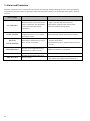
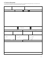
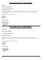
1
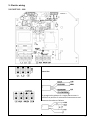
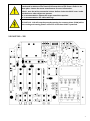
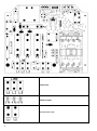
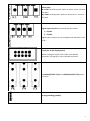
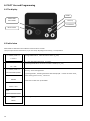
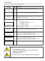
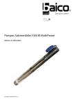
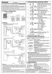
Operating Manual pilot manPILOT_eng_03.docx Index 1. PILOT Introduction ............................................................................................................................................................ 3 2. Safety Instructions ............................................................................................................................................................. 3 3. Technical characteristics .................................................................................................................................................... 4 4. PILOT wall mounting ......................................................................................................................................................... 4 5. Electric wiring .................................................................................................................................................................... 5 5.1 PILOT 112 - 118 ........................................................................................................................................................................ 5 5.2 PILOT 312 – 325 ....................................................................................................................................................................... 7 6. PILOT Use and Programming ............................................................................................................................................10 6.1 The display ............................................................................................................................................................................. 10 6.2 Initial view .............................................................................................................................................................................. 10 6.3 Setting menu ......................................................................................................................................................................... 11 7. Alarm and Protection .......................................................................................................................................................12 8. Technical Assistance .........................................................................................................................................................13 2 1. PILOT Introduction PILOT is an electronic device for the control of single phase and three phase motors (pumps) which provides protection against : Overcurrent, phase loss, excessive number of starts. The backlit LCD displays the running current and PILOT stops the pump if the maximum value set by the user is exceeded. The maximum number of pump starts is also user selectable and PILOT will stop the pump operation if this value is exceeded. Dry running PILOT provides a display of the power factor value (P.F. or cosø) and allows the user to set a minimum threshold value for normal operation. PILOT will stop the pump below this value to protect against dry running. PILOT will make up to 5 automatic restart attempts following an alarm condition at time intervals set by the user. PILOT stores in memory the number of pump starts and total running hours. The alarm history is also stored to assist with servicing. The body is constructed entirely of aluminium, making PILOT extremely solid and easily cooled. The IP55 protection makes it possible to install PILOT even in humid and dusty environments. 2. Safety Instructions Nastec strongly suggests to read carefully this operation manual before using and installing its products. Any operation (installation, maintenance and repair) must be carried out by trained, skilled and qualified personnel. Failure to observe and follow the instructions in this manual may result in dangerous and potentially lethal electric shock. Pay attention to all standard safety and accident prevention regulations. The device must be connected to main power supply via a switch to ensure the complete disconnection from the network before any operation on the PILOT itself (including visual inspection) and/or on the connected load. Disconnect PILOT from the main power supply before commencing any work. PILOT is set on automatic restart once the electric power supply is restored. Do not remove, for any reason, the cover and the cable plate without having first disconnected the device from the main power supply and having waited at least 5 minutes. PILOT and pumping system must be grounded properly before operation. For the entire period PILOT is powered, high voltage is present on the output terminals of the inverter whether or not the pump is running. Tightening all 4 screws on the cover with washers is recommended before powering the device. Otherwise, there may be a failure to connect the cover to ground, creating the risk of electric shock or even death. Avoid any shock or significant impact during transport. Check the PILOT immediately upon delivery and check for damage and/or missing parts. If either occurs, immediately notify the supplier. Damages due to transport, incorrect installation, or improper use of the device will null and void the warranty. Tampering or disassembly of any component will automatically void the warranty. NASTEC cannot be held responsible for any damages to people and/or property due to improper use of its products. 3 3. Technical characteristics Model Voltage [+/- 10%] 50/60 Hz Max current Weight [kg] PILOT 112 PILOT 118 PILOT 312 PILOT 325 PILOT 330 1 X 230 VAC 1 X 230 VAC 3 X 400 VAC 3 X 400 VAC 3 X 400 VAC 12 A 18 A 12 A 25 A 30 A 2 2 2,2 2,4 2,4 PILOT 112 115V PILOT 118 115V PILOT 312 230V PILOT 325 230V PILOT 330 230V 1 X 115 VAC 1 X 115 VAC 3 X 230 VAC 3 X 230 VAC 3 X 230VAC 12 A 18 A 12 A 25 A 30 A 2 2 2,2 2,4 2,4 * single phase models do not includes capacitor (available upon request) Max. ambient temperature: 40°C (104 °F) Max. altitude : 2000 m Protection grade: IP55 (NEMA 4) 4. PILOT wall mounting It is recommended to install the device in a ventilated ambient and protected by the direct sunlight. IP55 protection grade is granted with perfect tightness of the cover screws and cable glands. WARNING: wall plugs and screws for wall mounting are not included in the package. 4 5. Electric wiring 5.1 PILOT 112 - 118 Power line Motor output: To recognize the phases of a single phase motor is sufficient to perform 3 resistance measurements and compare the values as follows: 5 Running capacitor. Starting capacitor P.S. Starting capacitor must be switched off at the end of starting process with an external relay controlled by a special timer (3 sec) or by a voltmeter relay . 230 VAC , hot contacts when PILOT is powered. 230 VAC, hot contacts only if the PILOT runs the motor. Alarm relay: NC, COM: normally closed : when an alarm occurs, contacts will open. NO, COM: normally open: when an alarm occurs, contacts will close. Digital input contacts: to run and stop the motor: 1. 0V,IN1 2. 0V,IN2 Digital input contacts can be configured via software as NO or NC. Connector to the display board. Before closing the PILOT cover make sure that the connector is properly fit into its female connector. 2 x 25 AMP power line fuses Re-programming gateway 6 The choice of the running capacitor (PSC) and the starting capacitor (SC) must be conducted in relation to the electrical characteristics of the motor shown in the data plate. Contact the motor manufacturer for more information. Check , once the wiring connection is done, before closing the PILOT cover, inside the device no other objects are present. It is recommended to tighten the straps around the capacitor. It is recommended to use cables with lugs. Il PILOT 112 - 118 will stop the pump by opening the common phase (COM) whilst the running and starting phases are hot for all the time PILOT is powered. 5.2 PILOT 312 – 325 7 Power line Motor output Line and motor earth 8 Alarm relay: NC, COM: normally closed : when an alarm occurs, contacts will open. NO, COM: normally open: when an alarm occurs, contacts will close. Digital input contacts: to run and stop the motor: 1. 0V,IN1 2. 0V,IN2 Digital input contacts can be configured via software as NO or NC. Connector to the display board. Before closing the PILOT cover make sure that the connector is properly fit into its female connector. 3 x 16 AMP (PILOT 312) or 3 x 30 AMP (PILOT 325) power line fuses Re-programming gateway 9 6. PILOT Use and Programming 6.1 The display ENTER Motor STOP Alarm RESET Scroll up Scroll down Motor START 6.2 Initial view When PILOT is switched on the software release number is shown. Then you open the user view which, as you can see by adjusting the scroll keys, is composed of: <<< START / STOP >>> I is the detected current value Pushing ENTER button, Imax set value is shown (I_max). I = XX.X A <<< START / STOP >>> P.F is the detected power factor (o cosphi) . By pressing ENTER di P.F minimum set value is shown (P.F._min) P.F = X.XX <<< START / STOP >>> STATUS:NORMAL/ALARM Motor Starts If STATUS is NORMAL no alarms occur Contrary, alarm message blinks. By pressing ENTER , following indications will be displayed: : number of motor starts, , motor working time in hours, , alarms list XXXXXX To exit to the initial view push ENTER . Motor Hours xxxxx h : xx m A: XX XXXXXXXXXXXXXXXXXXX Menù ENTER 10 If pressing ENTER, MENU is entered 6.3 Setting menu When PILOT is in STOP mode, by pressing ENTER key at the screen [MENU '/ ENTER] to access the setting menu. Press STOP button to exit the setting menu and return to the original display. defa ult parameter Description A password (default 001)is required to enter the setting menu- PASSWORD 001 XXX Amp. max. XX XX.X A Dry run P.F. 0.65 X.XX Restarts delay 10 XX m Max restarts 5 XX /m DIGITAL INPUT 1 N.O. N.O. / N.C. Maximum current absorbed by the motor above which the PILOT will stop the pump. It is equivalent to the rated motor current increased by 10% Minimum power factor value(cosφ) below which the PILOT will stop the pump. Dry running conditions is characterized by a low power factor. Contact the pump manufacturer for more information. If DRY RUN alarm occurs, , PILOT performs up to 5 attempts to restart the pump as follows:: 1° attempt after X minute 2° attempt after 2*X minuti (2 times X minute) 3° attempt after 4*X minuti 4° attempt after 8*X minuti 5* attempt after 16*X minuti If after the 5th attempt DRY RUN still occurs , PILOT will stop definitely the pump and WATER MISSING alarm is displayed Maximum number of restart after which PILOT will stop the pump . By selecting N.O. (normally open) PILOT runs the motor if the digital input 1 is open; motor will be stopped if the digital input 1 is closed. By selecting N.C. (normally closed) PILOT runs the motor if the digital input 1 is closed; motor will be stopped if the digital input 1 is opened. N.O. / N.C. By selecting N.O. (normally open) PILOT runs the motor if the digital input 2 is open; motor will be stopped if the digital input 2 is closed. By selecting N.C. (normally closed) PILOT runs the motor if the digital input 2 is closed; motor will be stopped if the digital input 2 is opened. CHANGE PASSWORD Press ENTER to change the password to enter the setting menu. (default 000). DIGITAL INPUT 2 N.O. ENTER PILOT restarts the load automatically and without prior notice if: Lack of water (after 5 attempts). After a power supply recovery if the PILOT was running the pump. Opening or closing a digital input. Undervoltage alarm reset . Disconnect PILOT from the main power supply before commencing any work. 11 7. Alarm and Protection Whenever a protection occurs, the STATO screen you will see a blinking message indicating the alarm. Pressing STOP (only and exclusively at STATO screen) it is possible to restore the pump.If the alarm is not resolved Pilot starts again in showing the alarm. Alarm message 12 Alarm description ALL AMP MAX. Motor overload: input current of the motor is higher than the rated motor current set in the initial setting parameters. PHASE FAILURE Zero current on the COM phase (singlephase motor) or on T1 phase (threephase motor) Possible solution Make sure that the set value of input current is higher of at least 10% of the rated one. Check other possible causes of overcurrent. Check for possible missing phases. Check if load is properly connected Check the load and the cable wiring connection DRY RUN WATER MISSING Detected P.F. (power factor) is lower than Dry run P.F.set value. Check if the pumps is primed and check the presence of the water Check if the Dry run P.F. (power factor) set value is correct . KEYBOARD FAULT A button on the keyboard has been pressed for more than 1 minute Make sure button are not pressed DIGITAL INPUT Digital input opened /closed Check the input digital configuration. MAX RESTARTS Number of pump starts higher than the set number. Check about the possible causes (pressure switch, float switch, pre-charge pressure of tank, etc..) 8. Technical Assistance For more technical information contact the authorized reseller providing the following information. The solution to the problem will be found faster and easier if full information is provided. model Serial code Software release _.__ Line Voltage: ___ [V] Line frequency 50 Hz 60 Hz Description of the probelm: Motor type: single phase submersible three phase surface If submersible : motor cable lenght [m]: _____ If submersible : motor cable size [mm2]:____ P2 motor [kW]:____ Motor rated current [A]:__ Motor rated voltage [V]:___ Motor rated frequency :___ If singlephase : Capacitor value If single phase: motor starting current Pump performances _____ [UF] I st = _____ [A] Q = ____ [l/min] H = ____ [m] Pressure tank volume _____ [litre] Precharge pressure: _____ [bar] Electric and hydraulic chart: set parameters: please fill the software scheme with set parameters as attachment to this report or send it to us by FAX 13 DICHIARAZIONE DI CONFORMITA’ Secondo: Direttiva Macchine 2006/42/CE Direttiva Bassa Tensione 2006/95/CE Direttiva EMC 2004/108/CE PILOT è un dispositivo elettronico da collegare ad altre macchine elettriche con le quali viene a formare singole unità. E’ necessario, pertanto, che la messa in servizio di questa unità (corredata di tutti i suoi organi ausiliari) sia effettuata da personale qualificato. Il prodotto è conforme alle seguenti normative: EN 61000-6-3 EN 61000-6-1 EN 60335-1 Vicenza, 10/10/2011 Ing. Marco Nassuato Operation Manager DECLARATION OF CONFORMITY In according with: Machine Directive 2006/42/EC Low Voltage Directive 2006/95/EC EMC Directive 2004/108/CE PILOT is an electronic device to be connected to other electrical equipment with which it is to form individual units. It must, therefore, that the putting into service of this unit (with all its subsidiary equipments) to be performed by qualified personnel. The product conforms to the following regulations: EN 61000-6-3 EN 61000-6-1 EN 60335-1 Vicenza, 10/10/2011 Ing. Marco Nassuato Operation Manager 14 NOTE Copyright NASTEC srl Nastec reserves the right to modify without notice the technical features contained in this manual. Nastec srl, Via della Tecnica, 8, 36024, Mossano, Vicenza, Italy, Tel. +39 0444 886289, Fax +39 0444 776099, www.nastec.eu, [email protected] 15