1
FSF-AD8200A
8-Channel, 185MSPS JESD204B ADC FMC
Quick Start Guide
January, 2014
Version 1.0
Fidus Systems Inc.
35 Fitzgerald Road, Suite 400
Ottawa, ON K2H 1E6
CANADA
Tel: (613) 828-0063
Fax: (613) 828-3113
Fidus Systems Inc. is at the forefront of technology innovation and for this reason, reserves the right to alter, without notice, the specification, design or
conditions of supply of any product or service. Information provided by Fidus Systems is believed to be accurate and reliable. However, no responsibility is
assumed by Fidus Systems Inc. for its use, nor any infringements of patents or other rights of third parties, which may result from its use. No license is granted
by implication or otherwise under any patent or patent rights of Fidus Systems Inc.
© 2014 Fidus Systems Inc. All Rights Reserved. Fidus’ name, Fidus logo, and “FMCs by Fidus” brand, are trademarks of Fidus Systems Inc. Other registered
and unregistered trademarks are the property of their respective owners. Information is subject to change without notice.
FSF-AD8200A Quick Start Guide
Revision History
Revision
0.1
0.2
1.0
Author
EJD
EJD
ST
Release Date
2013.12.18
2013.12.19
2014.01.21
Fidus Systems Inc. – FMCs by Fidus
Description of Change
First Draft
Updated for Vivado® 2013.2
Updated. Released.
Page i of iii
FSF-AD8200A Quick Start Guide
Table of Contents
1. INTRODUCTION ............................................................................................................................................... 1 1.1 2. DOCUMENT PURPOSE .................................................................................................................................... 1 STEP-BY-STEP GUIDE ...................................................................................................................................... 1 2.1 CONNECT FSF-AD8200A FMC TO VC707 CARRIER CARD ............................................................................... 1 2.2 CONFIGURE THE HOST PC TO CREATE A VIRTUAL COM PORT, RUNNING OVER USB. ................................................ 1 2.3 LAUNCH TERA TERM PRO ............................................................................................................................... 2 2.4 CONFIGURE TERA TERM PRO “NEW CONNECTION” ........................................................................................... 2 2.5 CONFIGURE TERA TERM PRO SERIAL PORT ...................................................................................................... 3 2.6 LAUNCH VIVADO 2013.2 ............................................................................................................................... 4 2.7 IGNORE THE WARNING THAT 2013.2 HAS BEEN SUPERSEDED. ............................................................................ 4 2.8 OPEN THE EMPTY PROJECT ............................................................................................................................. 5 2.9 IGNORE WARNINGS FROM EMPTY PROJECT IN VIVADO ......................................................................................... 6 2.10 OPEN A HARDWARE SESSION .......................................................................................................................... 6 2.11 SELECT A TARGET .......................................................................................................................................... 7 2.12 PROGRAM FPGA ........................................................................................................................................... 9 2.13 OBSERVE COMMAND INTERFACE START .......................................................................................................... 11 2.14 CONFIRM THAT VIVADO RECOGNIZES THE ILA CORES ........................................................................................ 11 2.15 (OPTIONAL STEP) ATTEMPT TO CAPTURE DATA WITH ILA CORES ........................................................................ 12 2.16 NO ILA PROBES DETECTED ERROR MESSAGE ................................................................................................. 13 2.17 DEFINE A PROBES FILE................................................................................................................................. 13 2.18 REFRESH THE DEVICE .................................................................................................................................. 15 2.19 (OPTIONAL STEP) CAPTURE STATIC DATA USING ILA CORE ................................................................................ 15 2.20 OBSERVING THE CLOCK IS NOT INITIALIZED ..................................................................................................... 16 2.21 USING THE COMMAND INTERFACE TO INITIALIZE THE SYSTEM ............................................................................. 17 2.22 (OPTIONAL STEP) CONFIRMING THE CLOCKS ARE OPERATING AFTER INITIALIZATION .............................................. 18 2.23 CAPTURING NON-STATIC DATA WITH THE ILA CORES ........................................................................................ 20 Fidus Systems Inc. – FMCs by Fidus
Page ii of iii
FSF-AD8200A Quick Start Guide
Glossary
Term
Definition
CLI
Command Line Interface. A simple text-based interface that allows a user to read and
write register values, enabling hardware target operation and experimentation.
FMC
FPGA Mezzanine Card (VITA 57.1). A small board that plugs into an FMC connector,
such as on the VC707 evaluation board. These daughter boards usually add functions
that are too specialized to be included on a general purpose evaluation board. Often
they are input/output boards. Examples include input boards for video sampling and
compression, or output boards for motor control.
JESD204B A high-speed data transfer standard primarily targeted at data converters. The analogto-digital chips on the FSF-AD8200A FMC transfer their digitized data to the FPGA
using the JESD204B physical layer and protocol. Xilinx provides a JESD204B IP core
targeted at their programmable devices. The FSF-AD8200A demonstration bitfile
contains an instantiation of the Xilinx JESD204B IP core.
ILA
Integrated Logic Analyzer. An ILA is inserted into a Xilinx FPGA design using the Vivado
design tool from Xilinx. During debug or experimentation, the ILA can then be triggered
to capture data. This data can then be shown graphically or exported for postprocessing on a PC. ILA is similar to Xilinx’s previous Chipscope™ offering.
Tera Term
PRO
Tera Term PRO is a good quality, free, terminal emulator program. It is the example
terminal emulator referred to in both this guide as well as the VC707 documentation.
Vivado®
Xilinx tool enabling FPGA design, programming, and debug.
VC707
A Virtex-7® Development Kit sold by Xilinx®, containing a Virtex-7 FPGA and other
hardware; containing two FMC connectors (FMC1 and FMC2).
Fidus Systems Inc. – FMCs by Fidus
Page iii of iii
FSF-AD8200A Quick Start Guide
1. INTRODUCTION
1.1 Document Purpose
This document provides step-by-step instructions enabling customers to evaluate and experiment
with the FSF-AD8200A FMC when mated with a VC707 Development Kit. By following this guide, the
user will be able to evaluate and experiment with the FSF-AD8200A culminating in the capture of
analog signals. Following capture, the user may decide to export the digitized waveform for postprocessing in the signal processing tool of their choice.
This document and the demonstration code provided by Fidus assumes the following:
a) The Host platform is a VC707
b) The Host PC is a Windows system
c) Xilinx Vivado 2013.2 is installed correctly and will be used on the Host PC
d) Tera Term PRO is installed correctly and will be used on the Host PC
e) The end user has copied the FSF-AD8200A Project Directory to the Host PC. For the purposes
of the demonstration, a directory called "work" was created. An empty Xilinx project was then
placed under the “work” directory. This empty Xilinx project directory is provided by Fidus. No
source or other files are provided, the directory simply allows a Hardware Session to be
opened, which allows the user to download the FPGA bitfile and use the ILA cores to extract
and view graphed results. The source files for FPGA software and hardware are not provided.
2. STEP-BY-STEP GUIDE
2.1 Connect FSF-AD8200A FMC to VC707 carrier card
1. Ensure that the VC707 PCB is powered-down, and that you have exited Vivado and Tera
Term.
2. Ensure that the JTAG cable and the Serial-over-USB cables are connected between the
VC707 and the Host PC. For more information refer to Xilinx’s VC707 manuals.
3. Plug the FSF-AD8200A card onto the VC707’s J37 HPC2 connector. The bitfile will not work if
the FMC is plugged into the wrong FMC connector. Ensure the card is fully mated. Since the
FSF-AD8200A will hang off the edge of the VC707, you may want to relieve stress on the FMC
connector by supporting the weight of the FMC card (beyond the scope of this document).
4. Inspect your setup. If all looks correct. Turn the VC707 power switch ON.
2.2 Configure the host PC to create a virtual COM port, running over USB.
Refer to Xilinx’s documentation for specific instructions on establishing a virtual COM port to connect
to the VC707. For this guide, we assume that all necessary drives are already installed, and that
COM5 is configured as the virtual COM port. Note: This document uses COM5 as an example, but the
actual COM number will be assigned by the Host PC, and will likely not be COM5.
Fidus Systems Inc. – FMCs by Fidus
Page 1 of 21
FSF-AD8200A Quick Start Guide
2.3 Launch Tera Term Pro
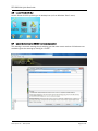
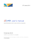
2.4 Configure Tera Term PRO “New Connection”
After launch, Tera Term will ask for new connection details. Select the "SERIAL" radio button and
using the “Port:” pulldown menu, find, and then select, the entry that mentions "Silicon Labs USB to
UART bridge". This will be your virtual COM port. In this example, the virtual COM port was
established as COM5. Click “OK”.
Fidus Systems Inc. – FMCs by Fidus
Page 2 of 21
FSF-AD8200A Quick Start Guide
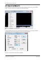
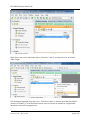
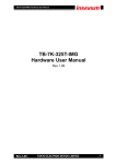
2.5 Configure Tera Term PRO Serial Port
On the top menu, click on the SETUP menu item, this will open a pulldown menu, select "SERIAL
PORT..." This menu allows you to configure your serial port interface.
Configure the Serial Port to be 8-N-1, with a baud rate of 115200. In the “Flow control” pulldown,
select Xon/Xoff. Set the transmit delay to be zero for lines and characters.
Click “OK”. Your terminal is now properly configured.
Fidus Systems Inc. – FMCs by Fidus
Page 3 of 21
FSF-AD8200A Quick Start Guide
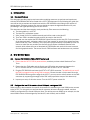
2.6 Launch Vivado 2013.2
Launch Vivado 2013.2 by clicking on its desktop icon (or from Windows “Start” menu).
2.7 Ignore the warning that 2013.2 has been superseded.
This warning is a normal message simply advising you that more recent versions of Vivado are now
available. Ignore the warning by clicking on “CLOSE”.
Fidus Systems Inc. – FMCs by Fidus
Page 4 of 21
FSF-AD8200A Quick Start Guide
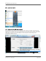
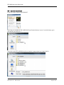
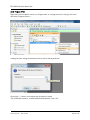
2.8 Open the Empty Project
In the FILE menu, click on OPEN PROJECT.
Assuming you installed the FSF_AD8200A Empty Project directory in your C:\work directory, go to
that directory and click on it.
Then click on the FSF_AD8200A.xpr file to load this empty project into Vivado 2013.2.
Fidus Systems Inc. – FMCs by Fidus
Page 5 of 21
FSF-AD8200A Quick Start Guide
2.9 Ignore warnings from Empty Project in Vivado
Warnings may appear. Click on “OK” to ignore them.
2.10 Open a Hardware Session
Look in the bottom left corner of the Vivado screen and click on "Open Hardware Session".
Fidus Systems Inc. – FMCs by Fidus
Page 6 of 21
FSF-AD8200A Quick Start Guide
2.11 Select a Target
The hardware session will open, now the user must connect it to a target. If this is your first run, click
on "Open a new hardware target". Otherwise, click on "open recent target".
The actual target name will appear similar to "localhost:60001..224A". Think of it as the software
driver which talks to the FPGA.
Once the hardware target is open, you will see the particular Xilinx Virtex® device on the VC707
board. It is called "xilinx_tcf/..." Usually it first is reported as "Closed". If you used it recently, it may be
reported as "Open".
Fidus Systems Inc. – FMCs by Fidus
Page 7 of 21
FSF-AD8200A Quick Start Guide
Right click on the word in the Status column ("Closed" or "Open"), to open the menu, and select
"Open Target".
This will declare the target driver xilinx_tcf/...224A to be "Open". It will also report that one FPGA is
present: XC7VX485T_0. If the FPGA was recently used, it may still be reported as "Programmed",
otherwise it will state "Unprogrammed".
Fidus Systems Inc. – FMCs by Fidus
Page 8 of 21
FSF-AD8200A Quick Start Guide
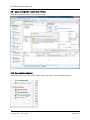
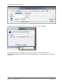
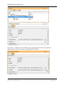
2.12 Program FPGA
Right-click under the Status column (on "Programmed" or "Unprogrammed") to bring up the menu
and select "Program Device...".
A dialog will open asking what bitstream file to send to the target device.
Click on the "..." button, and navigate the directories to select
"FSF_AD8200A/customer_release/datafiles/download.bit". Click “OK”.
Fidus Systems Inc. – FMCs by Fidus
Page 9 of 21
FSF-AD8200A Quick Start Guide
The previously selected path and file returns to the prior dialog. Click “PROGRAM”.
The programming of the FPGA begins. A status bar will indicate percent complete as the
download.bit file configures the FPGA. The total download time can vary, but generally, it takes about
30 seconds.
Fidus Systems Inc. – FMCs by Fidus
Page 10 of 21
FSF-AD8200A Quick Start Guide
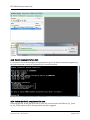
2.13 Observe Command Interface Start
If you switch to the terminal program during programming, you will observe that after programming
the initial Command> prompt is displayed by the command interface.
2.14 Confirm that Vivado recognizes the ILA cores
Once programmed, Vivado will report that it ‘sees’ two ILA cores within the FPGA: hw_ila_1 and
hw_ila_2. Both report as IDLE, meaning neither has been triggered.
Fidus Systems Inc. – FMCs by Fidus
Page 11 of 21
FSF-AD8200A Quick Start Guide
2.15 (Optional Step) Attempt to Capture Data with ILA Cores
For completeness, this optional step is intended to demonstrate the error message the user will
receive if the user tries to capture data before loading the probes file. Feel free to proceed directly to
section 2.17 if so desired.
While hovering over the "Idle" word under the Status column (for either ila_0 or ila_1), right-click to
bring up the menu. Click on "Run Trigger".
Fidus Systems Inc. – FMCs by Fidus
Page 12 of 21
FSF-AD8200A Quick Start Guide
2.16 No ILA Probes Detected Error Message
This error message indicates that there are no probes defined. This indicates that Vivado has not yet
been told how to interpret the data coming from the ILA cores.
2.17 Define a Probes File
Fix this problem by telling Vivado what probes are available. Under the box where the programming
file is defined, a second box is available to define the probes file.
Fidus Systems Inc. – FMCs by Fidus
Page 13 of 21
FSF-AD8200A Quick Start Guide
Click on the "..." button next to the Probes File box, and navigate up and over to select the
"debug_nets.ltx" file in the customer_release/datafiles directory.
Fidus Systems Inc. – FMCs by Fidus
Page 14 of 21
FSF-AD8200A Quick Start Guide
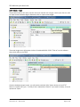
2.18 Refresh the Device
The user must now REFRESH the device to tell Vivado that a probes file has been defined. Hover
over the word "Programmed" next to the device listing (XC7VX485T…). Right-click and select "Refresh
Device".
Immediately after the refresh, the various Debug Probes will be visible in the bottom window. Vivado
and ILA are now ready to capture data.
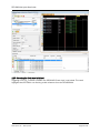
2.19 (Optional Step) Capture Static Data using ILA Core
For completeness, this optional step demonstrates the results of capturing data without first running
INIT (configuring the registers on the FSF-AD8200A). If desired, this step may be skipped and the
user can proceed directly to section 2.21.
Now that ILA has been set-up, clicking trigger will capture 8 channels of data instead of resulting in
an error. The captured data is shown in the waveform display. 64K samples are recorded for each of
the 8 channels. In the example below, the data is completely static, this is because the FSFAD8200A has not yet been configured for operation.
Fidus Systems Inc. – FMCs by Fidus
Page 15 of 21
FSF-AD8200A Quick Start Guide
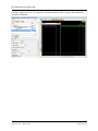
2.20 Observing the Clock is not Initialized
Triggering on hw_ila_2 reveals a problem- the JESD204B IP core clock is not locked. This result
highlights that the FPGA is not receiving a clock reference from the FSF-AD8200A.
Fidus Systems Inc. – FMCs by Fidus
Page 16 of 21
FSF-AD8200A Quick Start Guide
2.21 Using the command interface to Initialize the System
Within the terminal session, type "init" to initialize the FSF-AD8200A card.
Once <enter> is pressed, a long sequence of commands will be sent from the FPGA to both the FSFAD8200A card and to the JESD204B receiver IP core within the FPGA. This list of commands is
available within an appendix in the FSF-AD8200A User Manual.
Fidus Systems Inc. – FMCs by Fidus
Page 17 of 21
FSF-AD8200A Quick Start Guide
Wait for initialization to complete— it takes about 5 seconds. There are several pauses of 400ms to
meet the timing requirements of the ADCs (beyond the scope of this document).
2.22 (Optional Step) Confirming the Clocks are Operating after Initialization
For completeness, this optional step directs the user to confirm that a clock is now being received
from the FSF-AD8200A card following initialization. If so desired, this validation step may be skipped;
go directly to section 2.23.
Fidus Systems Inc. – FMCs by Fidus
Page 18 of 21
FSF-AD8200A Quick Start Guide
In Vivado, trigger on hw_ila_2, the waveform now shows that the clock is locked, and initialization
must have completed.
Fidus Systems Inc. – FMCs by Fidus
Page 19 of 21
FSF-AD8200A Quick Start Guide
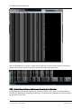
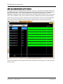
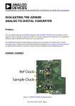
2.23 Capturing Non-Static Data with the ILA cores
The system is now fully configured and is ready to use hw_ila_1 to capture and display signals from
the JESD204B receiver. To drive all 8 analog inputs, an RF generator outputs a sine wave, which is
then split into 8 feeds. These 8 feeds are then connected to the 8 analog inputs on the FSFAD8200A. In Vivado, however over the "IDLE" word in the Status column next to hw_ila_1, and rightclick, select “TRIGGER”. After a few seconds the display is updated and waveforms are displayed.
Note, within ILA, the format of the waveforms can be defined by the user. For the following display,
the format was set to ANALOG, and the waveform height was set to 30 pixels for each trace.
This is a full collection of 64K samples from each of 8 channels. By zooming in, one can clearly see
the sine waves.
Fidus Systems Inc. – FMCs by Fidus
Page 20 of 21
FSF-AD8200A Quick Start Guide
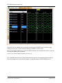
The display can be updated with new samples by clicking the TRIGGER button in Vivado or right
clicking on the hw_ila_1 status and then selecting “TRIGGER” from the menu.
Note that the digitized data being used by the ANALOG display can be saved within a file on the Host
PC using the following TCL command:
write_hw_ila_data filename.zip [upload_ila hw_ila_1]
This ‘recorded’ data can then be post processed on the Host PC. Post processing shows perfect or
near perfect alignment of all 8 sampled signals— a huge advantage of JESD204B Subclass 1!
Fidus Systems Inc. – FMCs by Fidus
Page 21 of 21