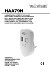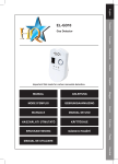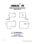
1
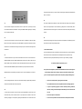
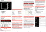
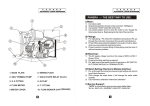
Wireless Gas Detection & Shut Off System - User Manual & Instructions
Please read and follow these instructions prior to installation of the system as correct installation is
critical to the performance of the system. The system has been designed for Residential premises to
detect harmful levels of combustible and / or toxic gases and provide visual and audible alarms when
preset levels are reached. When fitted the system will also activate a shut off device to close the gas
supply and prevent further build up. The installation of this system (or any detector) is no substitute for
the proper installation and maintenance of fuel burning appliances by a competent person in line with
the manufacturers or industry guidelines.
Effects of Carbon Monoxide (CO)
Carbon Monoxide is a highly toxic gas which is produced when fuels are burnt - it has no odour or
colour or taste to detect its presence. Exposure to high levels of carbon monoxide can cause many
symptoms and result in death. Symptoms can range from headache, nausea, vomiting and drowsiness
WIRELESS GAS DETECTION & SHUT OFF SYSTEM
INSTRUCTION MANUAL
through to unconsciousness, convulsions, cardio-respiratory failure and death.
The Flowtech System is the only wireless detection and shut off system produced under
exclusive license from the patent owner Linden Shield Ltd – WO 2003 / 106871
System Overview
The system comprises a Detector (or Detectors), a Control Panel and a Shut Off device (either a Valve
or an Actuator). The system has been designed to detect potentially harmful gas levels and provide
visual and audible alarms and communicate the alarm to a Control Panel which in turn will close off the
gas supply to prevent further increases in harmful gas levels (if the shut off device is fitted). The system
can manage up to 3 detectors and guidance on location of different types of Detectors can be found
below. Detectors can be used independent of the other devices and will provide visual and audible
© Flowtech Controls Ltd 2009
alarm only.
INSTALLATION GUIDE
FLOWTECH RECOMMENDS THAT ALL WIRING SHOULD BE UNDERTAKEN IN ACCORDANCE
WITH THE LATEST WIRING REGULATIONS OF THE INSTITUTE OF ELECTRICAL ENGINEERS
1.2 Natural Gas Detector(s)
It is recommended that a Natural Gas Detector is located approximately 30 cm below the ceiling and
at least 1.5m above the floor and within 4-5 m of a gas burning appliance.
Do not install or position the detector ...
1. Detector Location and fixing:
1.1 Carbon Monoxide Detector(s)
It is recommended that a CO Detector is located in every room in which a fuel burning appliance is
•
outside the premises
•
in damp, humid or dusty areas
•
above a gas cooker, gas boiler or fuel burning appliance
•
in a drafty area – e.g. close to a window or a doorway
•
where it can easily damaged
used. Due to the properties of Carbon Monoxide the detector should be positioned approximately
30 cm below the ceiling and at least 1.5m above the floor and a minimum of 1.5m away from any
1.3 Fixing Detector(s)
fuel burning appliance. If one CO Detector is being fitted in the premises it is advisable to position
the detector close to sleeping areas where it can he heard.
When you have chosen a location for your detector(s) ensure that the detector
can be connected to the required power supply. Do not connect it yet. or fix to
Do not install or position the detector...
the wall.. Wireless communications links need to be checked during installation
•
outside the premises
•
in damp, humid or dusty areas
•
above a gas cooker, gas boiler or fuel burning appliance
•
in a drafty area – e.g. close to a window or a doorway
•
behind furniture, curtains, blinds
•
in an area where the detector may be exposed to insecticide, air cleaners, glue, hair spay,
The Control Panel receives Wireless signals from the
or high levels of tobacco smoke
Detector(s) and provides power to the Shut Off
to ensure that the system operates fully.
2. Control Panel location and fitting
Device(s).
Please do not install the detector if the room is being decorated or contains new furniture. If it has
already been installed, please power off the detector and use a plastic bag to cover the detector to
protect it. Don’t remove the plastic bag until the room is ventilated fully, then power on the detector.
Location of the Control Panel will be such that the chosen Shut Off Device can be connected with the
lead from the Control Panel and the Control Panel can be connected to the power supply. This may
The warranty does not cover damage resulting from the above situations.
vary depending on the Shut Off Device selected. If the Valve option is chosen installation MUST be
made by a qualified Gas Installation Engineer.
When you have chosen a location for your Control Panel ensure that the Control Panel can be
4. Installation Check
connected to the required power supply. Do not power on yet or fix to the wall. Wireless
communications links need to be checked during installation to ensure that the system operates fully.
When the Actuator or Valve has been fitted and connected to the Control Panel, power on the Control
Panel and the Detectors to run an Installation Check, This sequence will check that the Detectors can
3. Actuator fitting and connections
conduct wireless communication with the Control Panel; that the Control Panel can supply signals and
power to the Shut Off Device; and that all Reset Functions are working correctly. We advise that this
The Actuator which closes the gas supply in the event of an alarm is designed to be fitted to the Gas
check is conducted prior to fixing the Detectors and Control Panel in place.
Meter Control Valve located next to the Gas Meter. The Actuator is supplied with 2 sets of metal fixing
brackets which secure the Actuator to the Gas Meter Control Valve. Select the brackets which match
4.1
the Gas Meter Control Valve and secure the Actuator to the Gas Meter Control Valve.
When power is supplied to the Control Panel the POWER light will be lit GREEN.
The Actuator has a Metal Control Arm which is secured around the Lever of the valve by 2 screws
(provided). During installation ensure that the Actuator is secure and that the Manual Reset button is
accessible. Tighten the 2 screws which secure the Arm to the Valve Lever. Connect the power supply
lead from the Actuator to the Control Panel.
4.2
When power is supplied to the CO (Carbon Monoxide) Detector(s) the GREEN LED POWER light will
be lit.
4.3
When power is supplied to the Gas Detector(s) the GREEN LED POWER light will start to flash. This
indicates the warm up period. It will stop flashing after approximately 3~5 minutes. This is required for
Metal Fixing Bracket
Manual Reset Button
Metal Control Arm
the sensor in the detector to stabilise and will occur whenever power is re-connected.
Valve option has been used in your system, re-open the Gas Supply be pulling down the Manual Reset
Button – see 3 above.
4.9
4.4
The system is designed to stop attempts to re-open the Shut Off Device during an alarm. Whilst the
The Control Panel is designed so that Detectors have to be “paired” with it by receiving an unique
Alarm is still running attempts to close the Actuator (by pulling down on the Reset Button) will be
Code. When all Detectors have stabilised – shown by the GREEN POWER Light being on constantly
prevented and the device will close again. If a Re-set cannot be made the override system is working
ON – this coding can take place.
correctly.
4.5
4.9
On the top of the Control Panel is a button. Press this button for 1 SECOND. The RED “TO CODE”
Ensure that the gas supply is open as your system check is now completed. Fix the Detector(s) and the
light will come on and the light will stay on for 30 SECONDS. During this 30 second period an unique
the Control Panel in place using the fixings provided.
code will be sent to all detectors within range so that they can “pair” and be able to send signals to the
Control Panel.
5. Post Installation Checks
It is recommended that you check your Detectors are functioning correctly every 3 months by pressing
4.6
the TEST button. Ensure that the Detectors are not damaged and remove any dust which may
To PAIR each Detector with your Control Panel PRESS the TEST button on each detector for 2
accumulate to ensure they can operate effectively. If the FAULT Light is lit contact your supplier.
SECONDS DURING THIS 30 SECOND PERIOD WHILE THE RED “TO CODE” LIGHT ON THE
CONTOL PANEL IS ON. If the Detector has been successfully paired and is within range the Control
The Detectors should be replaced every 5 years.
Panel will make 3 BEEP SOUNDS. Repeat until all detectors in your system have been checked.
IMPORTANT
This system has been designed to provide Visual and Audible Alarms in the event of dangerous
Additional Detectors can be added to your system at any time. To do this repeat steps 4.4, 4.5 and 4.6
gas levels being reached and close off the gas supply to prevent further build up of these
gases. It is vital that you protect yourself and other occupants by taking the following steps:-
4.7
To clear all pairings press button on top of the Control Panel constantly for approximately 40 seconds.
•
Get fresh air into the premises by opening doors and windows
The RED TO CODE LIGHT will be lit and then GO OFF.
•
Call a qualified technician and have the problem fixed before restarting appliances.
•
If anyone is experiencing symptoms of carbon monoxide poisoning: headaches,
4.8
dizziness, vomiting, call for Medical help and immediately move to a location that has
To test that the Control Panel can open and close the gas supply PRESS the TEST button on the
fresh air.
Control Panel and your shut off device will close. If your system uses the Actuator as the shut off
•
Ensure all occupants are accounted for
device the gas supply can be re-opened by pressing the RESET button on the Control Panel. If the
•
Do not re-enter the premises until it has been aired out and the problem corrected.
Warm Up Current
<60 MA
Static Current
<50 MA
To ensure the continued operation of your system we recommend the following steps be taken:-
Alarm Current
<150 MA
(a) Ensure that the holes and vents on the gas detectors and Alarm Panel are free from dust or
Static consumption
<1W
cobwebs. If they require cleaning disconnect the power and lightly brush the holes and vents with a
Alarm Consumption
<3W
soft brush
Alarm Volume
85 db
(b) Never use chemicals to clean the detectors or Alarm panel
Working Environment:
(c) Never allow water to enter the detectors of Alarm panel
Temperature
0-60°C
Humidity
<97% RH
5.2 Fault Lights
Alarm Density
Natural Gas 1000-5000PPM LPG 1000-10000PPM
In the unlikely event of a Gas Detector showing a YELLOW Fault Light will light up and the detector will
Response Time
<30 seconds
5.1 Maintenance
Wireless Range
200m (Open Ground)
sound. If this occurs, disconnect power to the detector, clean as above at 5.1 and re-connect the
The response time of this alarm conforms with EN50194
power supply. Repeat if necessary.
If this does not rectify the fault please contact your supplier for further assistance.
6.3
6.
Gas Lever Control
Technical Information
6.1
Working Environment:
Carbon Monoxide Detector
Power Supply
230v AC
Temperature
-10 - +50°C
Static Current
<140 µA
Humidity
<95%
Alarm Current
60 MA
Rated Voltage
DC 12 v
Operating Voltage
DC 6v – 18v
Alarm Volume
85 db
Rated Current
100 mA
Operating Current
20mA – 1000mA
Rated Power
1.2 W
Operating Power
0.24 W – 10W
Valve Closing time
5-10 seconds
Valve Opening time
5-10 seconds
Torque
30-60 kg.cm
Insulation resistance
>20MΩ
Gross Weight
395g
Dimensions
100mm x 90mm x 70mm
Working Environment:
Temperature
0-50°C
Humidity
25%-85%
Wireless Range
200m (Open Ground)
The response time of this alarm conforms with EN50291
CO Level PPM
50 PPM
100 PPM
300 PPM
400 PPM
Response Time
60-90 mins
10-40 mins
< 3 mins
Immediately
6.2
Power Supply
Gas Detector – Natural Gas / LPG
230v AC
© Flowtech Controls Ltd 2009