1
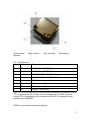
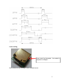
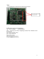
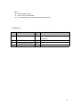
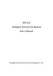
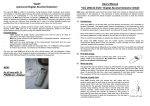
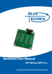
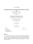
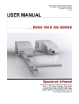
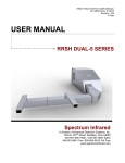
MINI INFRARED (NDIR)
CARBON DIOXIDE CO2 SENSOR
MODULE CM1104
USER MANUAL
ADD:Fenghuang No. 3 Road,
Fenghuang Industrial Park,
Eastlake Hi-tech Development
Zone, Wuhan 430205, China
Ver.2013.11
TEL:+86-27-81628831
FAX:+86-27-87405251
Wuhan Cubic Optoelectronics Co.,Ltd
[email protected]
Note: The data in the picture is for reference only, and the actual delivered goods shall prevail
1. Function
CM1103 CO2 gas sensor module is mainly used to test CO2 concentration,
indoor air quality measurement, such as CO2 measurement in ventilation
control system, building, school, hospital and CO2 control in air-conditioner,
mushroom, fireplace.
2. Working principle
CO2 gas is composed of different types of atoms have absorption spectrum in
infrared range. Absorption intensity abides by Lamber-Beer’s Law. Basic
working principle of NDIR sensor is as below,
Inlet
outlet
detector
Light
spectral filter
Basic mathematical model:A majority of both organic and inorganic polyatomic
gas have specific absorptive wavelength in infrared region. It observes
Lambert-Beer Law formula I = I0e-kpl when infrared light is coming through.
Light absorption intensity “i” can be described as i=I0-I= I0 (1- e-kpl).
I0:
intensity of incoming ray. I: transmitting beams. l :thickness of gaseous
medium. p: gas concentration. k: absorption coefficient.
3 Specification
Technology:
NDIR
Measurement range: 0-2000ppm,0-5000ppm,0-10000ppm
Max Drift: ±2%FS
Resolution: 10ppm
Response Time(T90): 30S
Accuracy : 40ppm+2% reading
Size: 41*43*16 mm
Repeatability : <2%
1
Sampling mothed : diffusion
Working voltage: DC5V±5%
Working current:average --70mA,peak---120mA
PWM ;linear output
UART: Data bit:8; Stop bit: 1; Check bit: null
Standard baud rate:9600bps
Working voltage: 0℃ ~ 50℃
Humidity : 0~95%RH non-condensing
Singal output :PWM.RS232-TTL,0-4V,I2C
Life Time:≥ 10years
4 Dimensions
4.1 schematic diagram
4.2Product Display
2
○
1 main board
○
5 probe
○
2 light source
4.3 I/O definitions
numbe Name
r
1
○
TX
○
3 air chamber
○
4 contact pin
Description
UART TX(SENDING)
○
2
RX
UART RX(RECEIVING)
3
○
+VI
POWER SUPPLY INPUT(+5V)
○
4
GD
POWER SUPPLY INPUT(GND)
○
5
P1
PWM 1
6
○
CL
Colck output(I2C reservation)
⑦
DA
Data output(I2C reservation)
⑧
P2
PWM2(Reservation)
Note: Pin1 and Pin2 are RS232 communication terminals on the board. RS232
TTL on the board is 0-3.3V, able to be compatible with 5V SCM. It should
convert TTL if connecting to the computer via RS232. For example: Using
transferred IC ADM3202.
RS232 communication reference diagram:
3
5 PWM output
PWM cycle:1004ms
Positive pulse width: (PPM/2)+2ms
PWM output diagram:
4
6 zero setting
short circuit for 3seconds , the model is
adjusted to 400ppm
Note: please do zero setting in Well ventilated areas
5
7 Note
The marked place in below picture must be hang in the air.
The socket place must
be hang in the air
8. After-sales services and consultancy
TEL:86-27-81628831
86-15623290125
ADD : Fenghuang No.3 Road, Fenghuang Industrial Park, Eastlake Hi-tech
Development
Zone, Wuhan 430205, China
FAX:86-27-87401159
Skype:shirley.wenya
Http://www.gassensor.com.cn
E-mail:[email protected]
6
Communication protocol
Baud rate:9600bps
Data bit:8
Stop bit:1 Check bit:null
Summary:
1. The data in the explanation are all hex data. Such as 46 is decimal [70]
2. [xx] is single byte data(no symbol,0-255) ;(xx) is double byte data, signed integer
(-32768 to +32767),the top one is ahead. “―― “ followed by explanation;
3. All the data are integer. It has (100, 10, and 1) times relationship with true data.
4. The length of command byte is [LB]+3.
Command Format:
Send: [IP] [LB] [CMD] [DF] [CS]
[IP]
address(fixed as 11)。
[LB]
[CMD]
[DF]
[CS]
byte length followed does not include CS
command
parameter items with command, optional
CS= -(IP +LB+CMD +DF)
Response:
a.When the command is implemented correctly, it responses
[ACK] [LB] [CMD] [DF] [CS]
[ACK]=0X16 right command
[LB]
byte length followed does not include CS
[CMD]
command
[DF]
parameter items with command, optional
[CS]
CS=-(ACK +LB+CMD+DF)
b.When the command is not implemented correctly, it responses
[NAK] [LB] [CMD] [EC] [CS]
[NAK]=0X06 Command is not implemented correctly
[LB]=2
byte length followed does not include CS
[CMD]
command
[EC]
the error code that command is not implemented correctly
[CS]
CS= -(NAK +LB+CMD+DF)
7
[EC]
01 Order length is wrong
02 There is no this command
03 Can't implement this command under current status.
Function list
No
Function
C
Description
MD
1.
Check measuring results
0x01
2.
Check software version
0x1E
3.
Check equipment nubmer
0x1F
4.
Zeroing
0x03
Besides measuring data, it also has status
information
8