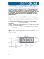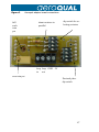
1
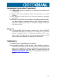
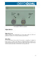
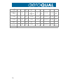
Series 940 & 945
Transmitter/Controller
User Guide
1
Quick Start Guide
1.
2.
3.
Unpack monitor and check supplied components are
correct
Connect 24 VDC power supply to 5 pin connector pins
Configure monitor
Using computer:
•
Attach twisted pair cable to RS485 pins on 8-pin
connector
•
Connect twisted pair to RS485 converter connected to computer
•
Load and run Configuration software
•
Turn on monitor
•
Configure monitor setpoints, ID etc.
Using R900:
•
Connect R900 to monitor and follow instructions in
R900 manual
4.
Connect Outputs
(A) If RS485 see “Operation as RS485 Transmitter”
(B) If 4-20 mA see “Operation as 4-20mA Controller”
(C) If Relay controller see “Operation as Relay Controller”
(D) If Display is fitted and the 4-20 mA loop is not being
used see “Operating the LED Display if 4-20 mA loop
is not being used”
5.
6.
Connect inlet filter and sample tubing if required
Power on and allow monitor to warm up for a few hours to
reach optimum operation
2
Table of Contents
Quick Start Guide
Table of Contents
Foreword
Statement of Compliance
Warranty
For Your Safety
WARNING
Technical Support
Description
Components Supplied
Components not supplied but required
Connector Descriptions and Output Specifications
Operation.
Warming up
Standby
Installing the inlet Filter and Tubing
1
2
3
4
5
7
7
7
8
8
8
11
12
12
12
13
Operating the LED Display if 4-20 mA loop is not being used 14
Operation as a relay controller
15
Operation as a 4-20 mA transmitter
17
4-20 mA wiring diagram for Loop and Display (with opto-isolation) 18
420 mA wiring diagram for Loop and Display (no opto-isolation) 19
Operation as a RS485 Transmitter
20
Network Settings
21
Configuring the S940/S945
21
Connecting the R51: RS-485 to RS-232 Converter
22
Installing Moxa RS485 to USB Converter
23
Procedure
23
Care and Maintenance
26
Troubleshooting
27
Diagnostics
30
Appendix A
S940/S945 Specification and Photographs
31
Photographs
31
External view of S940 with display
32
Appendix B
Removing the sensor head
33
Appendix C
Sensor Head Specifications
34
Appendix D
Series 940 and 945 RS485 Protocol
36
APPENDIX E
Calibrating the LED display
38
3
Foreword
Copyright Aeroqual Limited. All rights reserved. Reproduction, transfer, distribution or storage of part or all of the contents of this document in any form without
the prior written permission of Aeroqual Limited is prohibited.
“Aeroqual” and “Aeroqual Limited – Making the Invisible Visible” are registered
trademarks of Aeroqual Limited. Other product and company names mentioned
herein may also be trademarks or trade names.
Aeroqual operates a policy of continuous development. Aeroqual reserves the
right to make changes and improvements to any of the products described in this
document without prior notice.
Under no circumstances shall Aeroqual be responsible for any loss of data or
income or any special, incidental, consequential or indirect damages howsoever
caused.
The contents of this document are provided "as is". Except as required by applicable law, no warranties of any kind, either express or implied, including, but not
limited to, the implied warranties of merchantability and fitness for a particular
purpose, are made in relation to the accuracy, reliability or contents of this document.
Aeroqual reserves the right to revise this document or withdraw it at any time
without prior notice. The availability of particular products may vary by region.
Please check with the Aeroqual dealer nearest to you.
© Aeroqual Limited 2009. All rights reserved.
03.02.09
Aeroqual Limited
109 Valley Road, Mount Eden, Auckland, New Zealand
phone
+64 9 623 3013
fax
+64 9 623 3012
email
[email protected]
web
www.aeroqual.com
4
Statement of Compliance
1.
The Aeroqual Series 940/945 Transmitter/Controller complies with EN 50082
-1: 1997
2. The Aeroqual Series 940/945 Transmitter/Controller complies with EN 50081
-1: 1992
3. The Aeroqual Series 940/945 Transmitter/Controller comply with Part 15 of
the FCC Rules. Operation is subject to the following two conditions:
(i) these devices may not cause harmful interference, and
(ii) these devices must accept any interference received, including interference that may cause undesired operation.
NOTE: This equipment has been tested and found to comply with the
limits for a Class B digital device, pursuant to Part 15 of the FCC Rules.
5
Warranty
Thank you for purchasing this Aeroqual product. To get maximum use of the features of your new product we recommend
that you follow a few simple steps:
Read the guidelines for safe and efficient use.
Read all the terms and conditions of your Aeroqual
Warranty.
Save your original receipt. You will need it for warranty
repair claims. Should your Aeroqual product need
warranty service, you should return it to the dealer from
whom it was purchased or contact Aeroqual.
Our Warranty
Aeroqual warrants this product to be free from defects in
material and workmanship at the time of its original purchase by a
consumer, and for a subsequent period as stated in the following
table:
Products
Warranty Period
Series 940/945 Transmitter/Controller
One year from the date of purchase
Sensor heads – all gases
Six months from the date of purchase
Other Accessories
One year from the date of purchase
This warranty is expressly limited to the original owner who purchases the equipment directly from Aeroqual or from an
authorized Aeroqual dealer.
What we will do
If, during the warranty period, this product fails to operate under normal use and service, due to improper materials or workmanship, Aeroqual subsidiaries, authorized distributors or authorized service partners will, at their option, either repair or replace
the product in accordance with the terms and
conditions
stipulated herein.
6
Conditions
The warranty is valid only if the original receipt issued to the original purchaser by
the dealer, specifying the date of purchase, is presented with the product to be repaired or replaced. Aeroqual reserves the right to refuse warranty service if this information has been removed or changed after the original purchase of the product from
the dealer.
If Aeroqual repairs or replaces the product, the repaired or replaced product shall be
warranted for the remaining time of the original warranty period or for ninety (90)
days from the date of repair, whichever is longer. Repair or replacement may be via
functionally equivalent reconditioned units. Replaced faulty parts or components will
become the property of Aeroqual.
This warranty does not cover any failure of the product due to normal wear and tear,
damage, misuse, including but not limited to use in any other than the normal and
customary manner, in accordance with Aeroqual’s user guide for use, faulty installation, calibration and maintenance of the product, accident, modification or adjustment, events beyond human control, improper ventilation and damage resulting from
liquid or corrosion.
This warranty does not cover product failures due to repairs, modifications or improper service performed by a non-Aeroqual authorized service workshop or opening
of the product by non-Aeroqual authorized persons.
The warranty does not cover product failures which have been caused by use of nonAeroqual original accessories.
Tampering with any part of the product will void the warranty.
Damage to the sensors can occur through exposure to certain sensor poisons such as
silicones, tetraethyl lead, paints and adhesives. Use of Aeroqual sensors in these
environments containing these materials may (at the discretion of Aeroqual) void the
warranty on the sensor head. Exposure to gas concentrations outside of the design
range of a specific Aeroqual sensor head can adversely affect the calibration of that
sensor head and will also void this warranty as it applies to the replacement of sensor heads.
Aeroqual makes no other express warranties, whether written or oral, other than
contained within this printed limited warranty. To the fullest extent allowable by law
all warranties implied by law, including without limitation the implied warranties of
merchantability and fitness for a particular purpose, are expressly excluded, and in
no event shall Aeroqual be liable for incidental or consequential damages of any
nature whatsoever, however they arise, from the purchase or use of the product, and
including but not limited to lost profits or business loss.
Some countries restrict or do not allow the exclusion or limitation of incidental or
consequential damage, or limitation of the duration of implied warranties, so the
preceding limitations or exclusions may not apply to you. This warranty gives you
specific legal rights, and you may also have other rights, which may vary from country to country.
7
For Your Safety
Read these simple guidelines. Ignoring these guidelines may be hazardous.
USE SENSIBLY
Use only as per this user guide.
USE AEROQUAL APPROVED SERVICE
Only approved service personnel must work on this product.
ACCESSORIES
Use only approved accessories. Do not connect incompatible products.
CONNECTING TO OTHER DEVICES
When connecting to any other device, read the appropriate user guide
for detailed safety instructions. Do not connect incompatible products.
HAZARDOUS ENVIRONMENTS
Do not use the Gas Sensors in or near volatile fuel or chemicals.
HEALTH AND SAFETY IN THE WORKPLACE
The Aeroqual Series 940/945 Transmitter/Controller and Sensor Heads
are used to monitor ambient gas concentrations. Aeroqual does not
guarantee user safety. In hazardous environments, an appropriate
Health and Safety plan should be in place.
WARNING
Do not expose the monitor to gas concentrations outside the
range of the specific sensor head.
Do not switch the monitor on before reading the User Guide.
Do not open the product enclosure or attempt to remove the sensor head while the unit is powered up.
Technical Support
Technical information, service and spare parts are available through
your distributor. In addition, world wide technical support is available
from Aeroqual Ltd. Please contact:
Aeroqual Limited
109 Valley Road, Mt Eden, Auckland 1024, New Zealand
Phone: +64 9 623 3013
Fax: +64 9 623 3012
Email: [email protected]
8
Description
The Aeroqual Series 940 Transmitter / Controller is designed to
measure and control gas concentrations, and to communicate to a variety of hardware systems. The Series 945 also measures Temperature
and Relative Humidity and transmits this on the RS485 output. The
monitor contains a pump to provide sample flow and up to 5m of sample tubing can be attached to the inlet to enable remote sampling.
The Series 940/945 Transmitter /Controller can operate as a relay controller with user controlled setpoints, as 4-20 mA gas transmitter and it
can communicate via RS485 on a network. Series 900 PC Networking &
Data logging Software for connecting a RS485 network of S940/S945
monitors to a computer is available as an option. Please contact your
distributor if you require this.
The S940/S945 monitors can be supplied with or without a LED display.
If you have ordered a monitor with display the 4-20 mA loop will need
to be powered in order for the display to function correctly. If the loop is
not powered then the display will typically display -.125.
Components Supplied
Series 940 or 945 base unit (transmitter / controller)
Gas Sensor Head (installed)
Temperature and Relative Humidity Sensor (S945 only)
User guide & Configuration Software CD
Enclosure mounting brackets
2 x Male cord connectors (8-pin & 5-pin)
1 x external filter with fittings
Please check that all these components have been supplied and contact
your dealer or Aeroqual on email at: [email protected] if any of the
components are missing.
Components not supplied but required
24VDC 1A power supply
RS485/RS232 converter or RS485/USB converter
PC for configuring the monitor.
Multi-strand twisted pair cables for connections
9
Digital Communication Systems (Multi-Sensor Networks)
The Series 940 and 945 are designed to operate as part of a network
system with computer-based systems or PLC controllers.
A full range of measurement and control functionality is offered for digital systems.
Each unit can be given a unique ID (required for digital networking systems)
The set-up for digital network communications requires termination resistors on the RS485 communication lines to be correctly set.
Section 11, See operation as a RS485 transmitter.
Gas Measurement Guidelines
The following information is presented to help users operate their Aeroqual S940/945 Transmitter/Controller in the most effective and
efficient manner.
Installation Guide
The S940/945 should be installed at a location that is free from contaminants that might affect the performance of the sensor head. Please
contact [email protected] for assistance with specific chemicals
that you believe may adversely affect the supplied sensor. In general
the S940/945 should never be exposed to:
- steam, fumes, water or chemical spray
- aggressive solvents
- high condensing humidity
- cooking vapors/aromas
- paint fumes
- high levels of dust
10
Permanent Controller Placement
The S940/945 has been designed to measure the ambient gas
concentration.
For indoor local area monitoring attach the controller to an inert
surface.
For leak detection mount the unit as close as possible to potential
gas leaks.
Ensure that the controller is protected from excessive water splashing, dust, vibration, excessive heat or cold, excessive swings in
humidity and gas concentrations outside the range of the specific sensor head.
Warm up
It is recommended that the sensor head for the Series 940/945
transmitter/controller is run for up to 24 hours prior to use as a
control or alarm function if it has been switched off for more
than 7 days. This will remove any surface contamination on the
sensor that may influence the accuracy of the sensor.
Calibration
The sensor head is calibrated prior to delivery.
Environmental conditions such as dust, high humidity, vibration,
chemicals and heat or cold as well as high concentrations of
gases may degrade the sensor performance and shorten the
sensor life. Please ask your local dealer or contact Aeroqual at
[email protected] about your application if you are in
doubt.
11
Connector Descriptions and Output Specifications
The connector designations are shown in the diagram and photograph
below. Their descriptions and use are detailed in the following table.
GND
24VDC
Standby
Diag
485 A
+12V (out)
485 B
High
+
_
Control
GND
4-20mA
Low
5 pin and 8 pin connectors as viewed from the outside of the box
5 pin connector
Power:
Connect input power (16-28VDC)
DIAG
This is set to GND when sensor fails, else floating. The output is an open collector
current sink. The maximum rating of the transistor output is 24VDC at 150mA.
GND
Ground
CNTRL
The output is an open collector current sink. The maximum rating of the transistor
output is 24VDC at 150mA. Should you connect a relay coil or any other inductive load
to the transistor outputs, a back EMF suppression diode must be fitted across the load.
If set to GND externally it puts the sensor head into Standby mode and the S940/945 into
Sleep mode. If set to GND again it will return to normal operation.
STDBY
8 pin connector
LoALM
HiALM
12 V
(out)
GND
RS485
A
RS485
B
+
(420mA
loop)
12
This is set to GND when low alarm point is reached, else floating. Use the Configuration Program
to setup. The output is an open collector current sink. The maximum rating of the transistor output
is 24VDC at 150mA. Should you connect a relay coil or any other Inductive load to the transistor
outputs, a back EMF suppression diode must be fitted across the load.
This is set to GND when high alarm point is reached, else floating. Use the Configuration
Program to setup. The output is an open collector current sink. The maximum rating of
the transistor output is 24VDC at 150mA. Should you connect a relay coil or any other
inductive load to the transistor outputs, a back EMF suppression diode must be fitted
across the load.
12VDC output from the S940 which can be used to power the 4-20 mA loop if optoisolation is not required. However if a display is fitted and the loop output is required
it is recommended that an external power supply be used otherwise problems associated
with high loop impedance and/or ground loops may arise.
Ground
Communication lines. These are used to communicate with and configure the S940/945.
4-20 ma loop connection. The output is opto-isolated and designed to be externally
powered with a voltage range of 12-24V. Maximum voltage is 30 VDC. It may be
powered using the 12 VDC output pin on the connector but this will remove the opto-isolation.
The maximum total loop resistance should be 100 ohms at 12V and 500 ohms at 24V.
The output is linearly proportional to concentration. The default concentration scale is
dependent on the concentration range of the sensor head type. The concentration scale can be
defined by the user using the Configuration Program. If the sensor fails the output will be 20 mA.
Photograph of S940 connectors
Operation.
Warming up
Please warm up the S940/S945 for a few hours after it is first unpacked to enable it to achieve maximum performance.
Standby
If the environment from which the monitor is sampling is subject to
liquid sprays or misting (eg cleaning or decontamination regimes) it is
recommended that the unit be put into STBY mode which turns off the
internal pump and stops contaminants entering the unit.
13
Installing the inlet Filter and Tubing
It is recommended that an inlet filter is installed at the entrance to any
tubing to prevent contamination of the inlet tubing. Install inlet filter as
shown. The filter should be a 5 micron pore size, PVDF or PTFE membrane filter, diameter at least 30 mm, hydrophobic. Sample tubing
should be a maximum of 5 m in length and be inert PTFE, FEP or PFA
tubing.
14
Operating the LED Display if 4-20 mA
loop is not being used
LED display models are designed to operate in conjunction with the
4-20mA circuit. If the 4-20mA output is not being used the display
can still be enabled by connecting two wire loops (see diagram below) on the 8-pin connector between,
a) the positive 4-20mA pin to the +12v output pin and
b) the negative 4-20mA pin to GND (ground).
GND
Stand
24VDC
Diag
+12V
High
Control
GND
+
485
485 B
+
4-20mA
_
Low
GND
24VDC POWER SUPPLY
15
Operation as a relay controller
The S940/S945 can be used as a simple relay controller using the
alarm or control outputs which are open collector current sinks. They
are set to ground when activated according to their setpoints. The
setpoints can be configured by computer using the supplied Configuration program or using a R900 programmer (see Aeroqual for more
information). It is recommended that the DIAG output is always used
to alert a sensor fault condition.
Procedure
1.
Connect 24 V DC power supply to 5-pin connector
2.
Connect alert relay/alarm to DIAG output on 5-pin connector if
required
3.
Connect relay ground toggle to STDBY pin on 5-pin connector
if required.
4.
Connect control relay to CNTL output on 5-pin connector if required.
5.
Connect relays to LoALM and/or HiALM alarm outputs on 8-pin
connector if required
6.
Power on and test response.
The description and operation of the outputs are given below:
DIAG
This output is designed to enable detection of sensor
faults. This is normally floating but is set to GND when
the sensor fails. Thus it can be considered a "switch"
which is closed when the sensor fails. This can be used
to activate an alarm or relay and can also be monitored
with a PLC. The output is an open collector current sink.
The maximum rating of the transistor output is 24VDC
at 150mA.
LoALM
This is set to GND when low alarm is activated. It is
floating at other times. Use the Configuration Program
to set the Lo alarm set point. The output can be used to
drive an alarm relay or similar. The alarm can be set to
trigger above or below the set point using the configuration software. The output is an open collector current
sink. The maximum rating of the transistor output is
24VDC at 150mA. Should you connect a relay coil or any
other inductive load to the transistor outputs, a back
EMF suppression diode must be fitted across the load.
16
HiALM
This is set to GND when high alarm is activated. It is
floating at other times. Use the Configuration Program to
set the Hi alarm set point. The output can be used to
drive an alarm relay or similar. The output is an open
collector current sink. The maximum rating of the transistor output is 24VDC at 150mA. Should you connect a
relay coil or any other inductive load to the transistor
outputs, a back EMF suppression diode must be fitted
across the load.
CNTRL
This is set to GND when the gas concentration is rising in
the range from below Control low set point to the Control
high set point at which stage, it is set to floating. It remains floating until the concentration falls below the Control low set point at which point, it is reset to ground. Use
the Configuration Program to set the Control set points.
This output can be used to control, for example, a gas
generator or vent in a process operation. The output is
an open collector current sink. The maximum rating of
the transistor output is 24VDC at 150mA. Should you
connect a relay coil or any other inductive load to the
transistor outputs, a back EMF suppression diode must be
fitted across the load.
STBY
STBY is a hardware toggle switch. If it is briefly pulsed
(about 50ms) to GND it puts the sensor head into
Standby mode and the S940 into Sleep mode. If pulsed
again to GND it will return to normal operation. This can
be used to protect the sensor during process room cleaning and/or to reduce power and extend sensor life when
the sensor is not needed.
Operation as a 4-20 mA transmitter
17
The Series 940/945 can be connected to a PLC or current sensing device
via the 4-20 mA output to provide concentration information. The output is linearly proportional to concentration. The full scale (20 mA) value
is factory set but can also be user configured with the Configuration
software supplied. If the sensor fails the output will be 20 mA. It is also
recommended that the DIAG (diagnostic) output be used to monitor for
fault conditions.
The 4-20 mA output loop is opto-isolated from the Series 940/945 unit
and it is recommended that it be powered by a separate power supply
with a voltage in the range 12-24 V applied with the correct polarity as
labeled. This will produce the most reliable connection method. If optoisolation is not important then the 4-20 mA loop may be powered by the
same power supply as the unit.
LED display models are designed to operate in conjunction with the 420mA circuit and the loop needs to be powered correctly for the display
to function correctly.
Procedure
1.
Connect the 4-20 mA loop on the 8-pin connector to the power
supply and current measuring device (eg PLC)
ensuring the polarity is
correct. Please refer to the diagrams below.
***Caution: if the polarity is incorrect the 4-20 mA output may
be permanently damaged ***
2.
3.
Power on the S940/945 and PLC
Check the PLC or current sensing device to ensure data is present.
4-20 mA wiring diagram for Loop and Display
(with opto-isolation)
18
GN
Standby
24VDC
Diag
485 A
+12V (out)
485 B
High
+
_
Control
GND
+
GND
24VDC POWER SUPPLY
4-20mA
Low
+
PLC
+
GND
24VDC POWER SUPPLY
4-20 mA wiring diagram for Loop and Display
(no opto-isolation)
19
GN
Standb
24VDC
Diag
485
+12V (out)
485
High
+
_
Control
GND
+
GND
24VDC POWER SUPPLY
20
Low
+
PLC
4-20mA
Operation as a RS485 Transmitter
The Series 940/945 unit can communicate over a RS485 bus. Each
monitor has an ID which can be user set via the Configuration software
and up to 255 units networked together. Aeroqual supplies a Configuration program to configure the S940/S945 over the RS485 - please refer
to the section in the manual to learn how to do this. Aeroqual can also
supply Networking software to set up a RS485 network of S940/S945
units linked to a computer. Alternatively the user can write their own
PLC or computer software to communicate with the S940/S945 based
on the protocol detailed in Appendix C. Please read the section on
RS485 Network Settings below to learn about setting up a network of
S940/S945.
Connecting via RS485
1.
Connect a 24 vDC power supply to the power input on the 5-pin
connector
2.
Use twisted pair cable to connect the RS485 lines on the 8-pin
connector to the RS485 hub, bus or converter .
3.
Power on the monitor and run the communication software
(either Aeroqual Networking Software or your own software) on your
computer or PLC
Network Settings
If the S940/S945 is to be used as part of a “daisy chained” RS485 network a number of settings need to be adjusted.
1.
Jumper settings
The termination resistors need to be set correctly to ensure the network
communication is stable. The jumpers JP1, JP2, JP3 are to install termination resistors on the RS485 communication lines. Remove the jumpers
J1, J2, J3 for all S940/945 units in a chain except the last S940/945 unit
in the network chain. If there is only one unit then set the jumpers in
place.
To access these jumpers remove the sensor head and then remove the
four screws on the mounting plate. The PC board (as shown below), is
located on the under-side of the fixing plate.
2.
ID Settings
The ID of the monitors on the network need to be unique so they can
be distinguished on the RS485 network. The ID of the unit is factory set
as 1 and therefore it will need to be changed. Use the Configuration
program to change the IDs (see the section on Configuring the monitors, p22).
21
Jumpers
Configuring the S940/S945
The Series 940/945 alarm and 4-20 mA output scale settings can be
modified using a computer and the supplied S900 Configuration Program or using a R900 purpose made hand held communication tool. For
further details on the R900 contact your supplier or Aeroqual Limited
([email protected]).
To configure the S940/S945 by computer you will need an RS232/RS485
or USB/RS485 converter. There are many RS232/RS485 converters on
the market. Only certain brands will function well with Aeroqual’s products. Aeroqual can supply a converter (R51) suitable for configuring a
single monitor (it is not suitable for a S940 network). Converters which
have been tested by Aeroqual can be purchased from Aeroqual or it’s
distributors, or contact Aeroqual for recommended brands on [email protected].
Computer requirements
CD-ROM Drive
RS232 port
Windows OS version 95 or later.
45 Mb of spare hard drive space
Additional components required:
24V power supply
RS232/RS485 or USB/RS485 converter
RS485 wired S940/S945
22
Connecting the R51: RS-485 to RS-232 Converter
Connect to
PC serial
COM port or
USB via R52
TD(A) connect to
RS485B
RS-485 to RS-232 Converter to Series
930/940
TD(A) connect to RS485B
TD(B) connect to RS485A
GND – not required
GND – not required
+12V – not required
TD(B) connect to
RS485A
Using a USB to RS485 converter
Recommended supplier: Moxa, www.moxa.com
Note: Aeroqual S900 series monitors communicate via 2 wire RS485
so the converter must be configured to RS485 2W using software supplied with the converter.
23
Installation instructions for version 1.5.0.0 of the Moxa
UPort1150 driver.
Configure a Moxa UPort 1150 for RS485-2 wire mode as follows:
1.
2.
3.
4.
5.
6.
7.
8.
9.
10.
Install software from the CD provided with Moxa UPort 1150
Attach Moxa UPort 1150 USB device to USB port
Once the drivers have been installed for the device, open up
the device manager (found under control panel/system/
device manager (Windows Vista), OR Control panel/system/
hardware/device manager (Windows XP)
Right-click on the UPort 1150 item and select properties
Expand the “Multi-port serial adapters” item
Click on the "Ports Configuration" tab
Select the appropriate COM port
Click on the button labeled “Port Setting”
Under heading “Interface”, select the “RS-485 2W” entry
from the drop down list
Click OK in this window and in the original window opened
from the Device Manager in step 5
Procedure for S940 / S945 operation
1)
Plug in and install the USB or RS232 to RS485 converter into
your computer.
2) Connect the Series 940/945 RS485 port leads to the converter
3) Install the Aeroqual Series 930/935 Configuration Program on
the computer if not already installed.
4) Power up the Series 940/945 unit.
5) Run the Aeroqual Series 940/945 Configuration Program.
6) Select Unit by entering the ID of the S940/945 you wish to
modify (and click on "Download” to download the unit’s current
values).
7) Modify settings
8) Click Upload to upload the settings to the S940/945
9) Click Exit
10) Power down the S940/945 and install.
24
Port ID
Click on “Port”
menu
and
select “Change port ID” to change ID to your requirement in the range
1 to 255.
Caution: if you are setting up a network please ensure each unit has a
unique ID otherwise there will be conflicts and data loss.
Alarms
High alarm and low alarm setpoints can be set by clicking on the appropriate window and entering the required activation setpoint. Please
note: High alarm setpoint must be greater than low alarm setpoint.
The low alarm trigger determines whether low alarm is activated by
being above or below the setpoint. Click mouse on the button to select.
The Alarms can be enabled or disabled by clicking on the button alongside Enable or Disable, respectively.
Control
The control output is triggered according to the band set by the Control
high and Control low values. Control high must be greater than Control
low. The action of this output is designed to enable control of an ozone
generator. The Control output will be "on" when the concentration is
rising in the range from below Control low until it hits Control high when
it turns off. It remains off until the concentration falls below Control low.
4-20 mA output scale
25
This sets the gas concentration scale that corresponds to 4 -20 mA.
Each sensor head type has a default setting but the user can modify this
by clicking the user define button and entering the required value that
corresponds to 20 mA.
(NOTE: The LED display is calibrated for the default settings only and
will not operate correctly if the default range is altered – if you are in
any way uncertain of this, please seek technical assistance from Aeroqual.)
Upload
Clicking this button uploads the settings to the S940/945.
Download
Clicking this button downloads the settings from the S940 or S945. Use
this function to check the settings are correct.
26
Care and Maintenance
Your Aeroqual S940/945 is a product of superior design and quality and
should be treated with care. When using your S940/945:
•
Keep it and all its parts and accessories out of the reach of small
children.
•
Keep it dry. Avoid water and/or condensation as humidity and
liquids containing minerals may corrode electronic circuits.
•
Do not use or store in dusty, dirty areas.
•
Do not expose sensor heads to higher levels of gas than its designed range.
•
Only operate within its specified temperature range. Avoid sudden changes in temperature will cause condensation that may
damage the electronic components.
•
Do not drop, knock or shake as this could lead to internal damage.
•
Do not use harsh chemicals, cleaning solvents or strong detergents for cleaning. Wipe with a soft cloth slightly dampened with
a mild soap-and-water solution.
27
Troubleshooting
Fault Description
Possible cause
Remedy
No power
Lead connection broken
Reconnect power lead
Power supply failure
Replace 24V power supply
S940/945 damaged
Replace unit
RS485 communications
unstable
RS485/RS232
faulty
adaptor Reconfigure/replace
adaptor
Connections broken
Reconnect leads
ID incorrect
Check ID
Noise on cable
use shielded twisted pair
cable
Sensor head not fitted
correctly
Insert head correctly
4-20 mA output failure
30V input exceeded
Replace S940/945
Network unstable
ID conflict
Modify IDs so that no
S940/945 units share the
same ID
Noise on leads
use shielded twisted pair
cable
Jumpers set incorrectly
Set jumpers correctly
S940/945 units too close
together
The leads between
S940/945 units should be
a minimum of 30 cm in
length.
Display shows -1
over-range (>20 mA)
reverse loop current
Loop polarity is incorrect.
Reverse this. Incorrect
loop polarity can cause
irreversible damage to the
S930/S940. Reduce loop
current.
Display shows
over-range loop current
(>20 mA)
Reduce loop current
4-20 mA Loop not powered
Power loop. The display
requires the loop to be
powered to read correctly
1
Display shows -.125
28
Display oscillates between Sensor head not fitted
min and max
correctly
Insert sensor head correctly
Sensor failure when new
sensor
Insufficient warm-up
Run the sensor for 24-48
hours
Air contaminated
Move the sensor to
cleaner environment and
check reading
Sensor damaged
Replace sensor
Sensor showing high
baseline reading under
zero gas conditions
Background gas
higher than normal
level Move sensor to clean air
and recheck baseline
Interferent gas present
Move sensor to clean air
and recheck baseline
Sensor zero drift
Re zero sensor in a clean,
stable background
Sensor damaged
Replace sensor
Flow incorrect
Measure sample flow and
compare with specification. If incorrect check for
leaks
and/or
replace
pump.
Sensor showing higher
Zero calibration incorrect
than expected reading in
the presence of sensor
Span calibration incorrect
gas
Sensor correct
Zero calibrate sensor
Span calibrate sensor
Check calibration of gas
generator.
Interferent gas present
Move sensor to clean air
and check reading upon
exposure to known gas
concentration
Sensor calibration lost
Replace /refurbish sensor
Flow incorrect
Measure sample flow and
compare with specification. If incorrect check for
leaks and/or replace
pump.
29
Sensor output noisy
S940/945 power supply Install regulated power
unregulated
supply
Local air flow too high
Reduce air flow
Environmental conditions Reduce fluctuations
fluctuating
Pump not working correctly
Sensor showing lower
Zero calibration incorrect
than expected reading
in the presence of sensor Span calibration incorrect
gas
Sensor correct
Replace pump.
Zero calibrate sensor
Span calibrate sensor
Check calibration of gas
generator.
Sensor inlet contaminated Clean sensor inlet filter
and mesh
Interferent gas present
Move sensor to clean air
and check reading upon
exposure to known gas
concentration
Gas reactive and decom- Move the monitor closer
posing before detection
to the source of the gas
Sensor calibration lost
Flow incorrect
30
Replace /refurbish sensor
Measure sample flow and
compare with specification. If incorrect check for
leaks and/or replace
pump.
Diagnostics
The S940/945 has inbuilt diagnostics to detect sensor faults. If the sensor fails it can be easily replaced by simply removing and installing a
new one (see sensor manual for details). The failed sensor can be sent
back to Aeroqual for refurbishment or disposal.
Table of fault condition diagnostics
Fault
description
No fault
DIAG output
floating
4-20 mA output
valid gas reading
Sensor
fault
failed
GND
20 mA
Sensor
fault
aging
GND
20 mA
Sensor
not
fitted correctly
GND
Oscillates between 4 and 20
mA
RS485 output
valid gas reading
Status1 = 0x00
last valid gas reading
Status1=0x01
last valid gas reading
Status1=0x02
no reply
31
Appendix A
Photographs
Power
Outputs
Inputs
Jumpers
Sampling Pump
Ingress Protection
Connectors
ID
RS485 protocol
Appendix C)
Enclosure
Mounting
Operating temperature
Operating relative humidity
Enclosure size
Sample Flow rate
S940/S945 Specification and
24VDC, 500mA (range 22-26 VDC)
4-20 mA (opto-isolated)
12-24 V (30 VDC max)
maximum loop resistance = 500
R at 24V.
4 x Relay outputs (Hi alarm, Low alarm,
Control, Diagnostics)
RS485 (two wire)
Standby toggle
J1, J2, J3 termination resistors for RS485
network
12V BLDC Rotary pump or 5V BLDC
diaphragm pump
IP40 equivalent
Screw
1 (Default)
User configurable from 1 to 255
Aeroqual proprietary protocol (see
Polycarbonate
Screw fix
-5°C and +40°C (23°F and 120°F)
5 to 95% non-condensating
230mm x 140mm x 95mm (LxWxH)
0.2 +/-0.1 LPM
Photographs
Height = 95 mm
The S945 has a
Temperature and
RH probe located
here
External view of S940 with display
32
Internal view of S940 with display. Note: internal filters may vary.
33
Appendix B: Removing and Replacing the
Sensor Head
d
c
A
c
B
Note: The S945 has a Temperature and RH probe located here
1)
Undo the four lid screws, remove lid and view the interior of the
enclosure as shown above.
2)
Unscrew the inlet & outlet nozzles “A” & “B” (Note: Turn the plastic
nut clockwise). Remember the small elbows form part of the sensor
head.
Now replace the sensor head (keyed to fit one way only) tighten
the inlet and outlet nozzles “A” and “B” (Note: Turn the plastic nut
anti-clockwise).
Replace the lid and tighten the four lid screws.
3)
4)
34
Appendix C
Sensor Head Specifications
Operational Range
Sensor
Calibrated
Range
Maximum
Exposure
LDL
Accuracy
Resolution
Response
Time
(T90)
Ammonia
0 - 100 ppm
0 - 100
200
0.5
ppm
<±5 ppm 0-100
ppm
0.1 ppm
<60 s
-20°C to 40°C
5 to 95%
100ppm
Ammonia (leak)
0 - 1000 ppm
01000
2000
2 ppm
<±15%
1 ppm
<60 s
-20°C to 40°C
5 to 95%
1000ppm
Carbon monoxide
0 - 100 ppm
0 - 100
200
0.5
ppm
<±5 ppm
0.1 ppm
<150 s
0°C to 40°C
5 to 95%
100ppm
Carbon monoxide
0 - 1000 ppm
01000
2000
1 ppm
<±10%
1 ppm
<150 s
0°C to 40°C
5 to 95%
1000ppm
Carbon dioxide
0 - 2000 ppm
02000
NA
-
<± (40 ppm +
3%)
10 ppm
<60 s
0 to 40°C
5 to 95%
2000ppm
Carbon dioxide
0 - 5000 ppm
05000
NA
-
<± (150 ppm +
5%)
10 ppm
<60 s
0 to 40°C
5 to 95%
5000ppm
Carbon dioxide
0 - 5.00%
05.00%
NA
-
<± 5%
0.01%
<60 s
0 to 40°C
5 to 95%
5%
05000
20000
5 ppm
<±10%
1 ppm
<90 s
-20°C to 40°C
5 to 95%
5000ppm
Hydrogen
sulphide
0 - 10 ppm 1
0 - 10
25
10 ppb
<±0.5 ppm
0.01 ppm
<60 s
-20°C to 40°C
5 to 95%
10ppm
Hydrogen
sulphide
0 - 50 ppm
0 - 50
100
0.05
ppm
<±1 ppm 0-10
ppm
<±2 ppm 10-50
ppm
0.1 ppm
<60 s
-20°C to 40°C
5 to 95%
50ppm
Methane
0 - 10000 ppm
09999
10000
-
<±15%
1 ppm
<60 s
0°C to 40°C
30 to 80%
10000ppm
Ozone
0 - 0.150 ppm
00.150
0.250
1 ppb
<±0.005 ppm
0.001
ppm
<70 s
-5°C to 40°C
5 to 95%
0.5ppm
Ozone
0 - 0.5 ppm
00.500
1
1 ppb
<±0.008 ppm 00.1 ppm
<±10% 0.1-0.5
ppm
0.001
ppm
<60 s
-5°C to 40°C
5 to 95%
0.5ppm
Ozone
0.5 - 20 ppm 2
0.5 - 20
25
10 ppb
<±10% 0.5-2 ppm
<±15% 2-20 ppm
0.01 ppm
<35 s
-5°C to 40°C
5 to 95%
20ppm
Nitrogen dioxide
0 - 0.2 ppm
00.200
0.500
1 ppb
<±0.01 ppm 0-0.1
ppm
<±10%
0.10.2 ppm
0.001
ppm
<180 s
0°C to 40°C
30 to 70%
0.2ppm
NMHC 3,4
0 - 25 ppm
0 - 25
50
0.1
ppm
<±10% 0.1-25
ppm
0.1 ppm
<60 s
-20°C to 40°C
5 to 95%
25ppm
Hydrogen
0 - 5000 ppm
1
Temp.
RH
6
Analogue
output
scale
35
NMHC 3,4
0 - 25 ppm
0 - 25
50
0.1
ppm
<±10% 0.1-25
ppm
0.1 ppm
<60 s
-20°C to 40°C
5 to 95%
25ppm
Perchloroethylene
0 - 200 ppm
0 - 200
250
1 ppm
<±5 ppm 0-50
ppm
<±10% 50-200
ppm
1 ppm
<5 s
(T50)
0°C to 40°C
30 to 80%
200
ppm
Sulphur dioxide
0 - 10 ppm
0 - 10
20
0.2
ppm
<±0.5 ppm
0.01 ppm
<60 s
-20°C to 40°C
5 to 95%
10ppm
Sulphur dioxide
0 - 100 ppm
0 - 100
200
0.5
ppm
<±10%
0.1 ppm
<60 s
-20°C to 40°C
5 to 95%
100
ppm
0 - 25
50
0.1
ppm
<±10% 0.1-25
ppm
0.1 ppm
<60 s
-20°C to 40°C
5 to 95%
25ppm
0 - 500
1000
1 ppm
<±10%
1 ppm
<60 s
-20°C to 40°C
5 to 95%
500
ppm
VOC
0 - 25ppm
3
VOC
0 - 500 ppm
4
Other Gases
36
Contact Aeroqual with specific requirements for gas and concentration
Appendix D Series 940 and 945 RS485 Protocol
Protocol Version 1.5 Date: 01-02-2005
The network communication is in master-slave mode, which means that a PC or
other device will be the network master. All information is requested by the network master. Otherwise no information is sent out by the S940/S945 network
units.
Section 1. General description of the communication commands (for
command details and data representations please refer section 4):
01.
Information request command to S940/S945. The basic format is a 5
bytes data stream:
BASE, COMMAND, NETWORK_ID, OTHERS, CHECKSUM
*
*
*
*
*
BASE - information request data stream header
COMMAND - 1 byte network unit action command
NETWORK_ID - 1 byte S940/S945 network ID.
OTHERS - may used to extend functions later, it can be left as empty for now
CHECKSUM - makes the data stream total sum byte value to zero.
02.
S940/S945 unit basic reply command format will be a 15 bytes stream
(see Section 2 for details):
SENSOR, COMMAND, NETWORK_ID, DATA1(4 bytes), DATA2(4 bytes), RESERVED, STATUS1, STATUS2, CHECKSUM
Section 2. S940/S945 Network ID specified commands. These commands generate a response by a specified S940/S945 unit. Every command needs a corresponding reply.
01.
Gas Data request command. The command asks for the gas data that
a specific S940/S945 unit currently holds. The S940/S945 unit responds
with an gas value. The gas data validity depends on the
DATA_UNVALID bit of STATUS1 flag (please see Section 4 for details).
Command: BASE, GAS_CONC_DATA, NETWORK_ID, EMPTY, CHECKSUM
Reply: SENSOR, GAS_CONC_DATA, NETWORK_ID, DATA1, TEMP, RH, RESERVED, STATUS1, STATUS2, CHECKSUM
* DATA1 - 4 bytes IEEE754 floating point data, measured gas value, if
DATA_UNVALID bit of STATUS1 flag is 1 then it will be last byte measured value,
otherwise it's new measured value.
* TEMP - 2 bytes int value, its actual value equals the int value divided by 10
(TEMP/10)
for its real temperature value of S945 unit
* RH
- 2 bytes int value, its actual value equals the int value divided by 10
37
(RH/10) for its real relative humidity value of S945 unit
* for S940 the field TEMP and RH will be always zero for firmware version 1.5
and later.
* However, for S945 firmware version 1.4 and earlier can't use this command to
request temperature and humidity.
02.
Standby command. The S940/S945 unit will set its sensor head to
standby state. The S940/S945 will set STANDBY bit of STATUS2 to 1 indicating it
is in standby mode. When the standby state has been terminated, it will reset
STANDBY bit of STATUS2 to 0.
Command: BASE, STANDBY, NETWORK_ID, EMPTY, CHECKSUM
Reply: SENSOR, STANDBY, NETWORK_ID, DATA1, DATA2, RESERVED, STATUS1,
STATUS2, CHECKSUM
* DATA1 and DATA2 - no meanings.
The reply just confirms that it performed action, to find it check status bit.
03.
Specific S940/S945 reset command. The command will reset the S940/
S945 at any time.
Command: BASE, RESET, NETWORK_ID, EMPTY, CHECKSUM
Reply: SENSOR, RESET, NETWORK_ID, DATA1, DATA2, RESERVED, STATUS1,
STATUS2, CHECKSUM
* DATA1 and DATA2 - no meanings.
* RESET - 1 byte reset command, see section 4 for details.
04.
Specific S940/S945 unit connected sensor head version number request
command and reply. PC or other devices can request sensor head version information through S940/S945 unit.
Command: BASE, SENSOR_VERSION, NETWORK_ID, EMPTY, CHECKSUM
Reply: SENSOR, SENSOR_VERSION, NETWORK_ID, VERSION_NUM,
PLAY_TYPE, NAME_LENGTH, SENSOR_NAME, RESERVED, CHECKSUM
DIS-
* VERSION_NUM - 1 byte, the version number of sensor head plugged in the
S940/S945 unit. Real version number is the value divided by 10.
* DISPLAY_TYPE - 1 byte, the decimal value display type, different gas sensor
head are different, see sensor head specifications for details
* NAME_LENGTH - 1 byte, the sensor head name length.
* SENSOR_NAME - 7 bytes max, valid length depends on NAME_LENGTH value,
the sensor head name ASCII code that connected to S940/S945 unit,
05.
Modify S940/S945 unit network ID command, that can change current
S940/S945 unit network ID.
Command: BASE, CHANGE_NETWORK_ID, OLD_ID, NEW_ID, CHECKSUM
Reply: SENSOR, CHANGE_NETWORK_ID, NEW_ID, DATA1, DATA2, RESERVED,
STATUS1, STATUS2, CHECKSUM
* CHANGE_NETWORK_ID - 1 byte command, see section 4 for details.
38
* OLD_ID - the S940/S945 unit old network ID, 1 byte
* NEW_ID - the S940/S945 unit new network ID, 1 byte
06.
Specific S940/S945 connected sensor gas unit ppm to mg/m3 convert
factor and analogue current max output scale factor value request command.
Command:
BASE, FACTOR_REQUEST, NETWORK_ID, EMPTY, CHECKSUM
Reply: SENSOR, FACTOR_REQUEST, NETWORK_ID, DATA1, DATA2, RESERVED,
STATUS1, STATUS2, CHECKSUM
* DATA1 - 4 bytes, gas unit ppm to mg/m3 convert factor floating point value
* DATA2 - 4 bytes, default S940/S945 4-20mA current output max scale factor
floating point value. See sensor head spec for details.
07.
the
Specified S940/S945 unit configure settings upload command, which set
S940/S945 unit alarm 1, alarm 2, defined output scale and alarm enable
settings. Total 25 bytes data stream.
Command:
BASE, PARAMETERS_UPLOAD, NETWORK_ID, EMPTY, CHECKSUM
Parameters: BASE, PARAMETERS_UPLOAD, NETWORK_ID, ALARM1, ALARM2,
DEFINED_SCALE, CONTROL_HIGH, CONTROL_LOW, ALARM_STATUS, CHECKSUM
Reply: SENSOR, PARAMETERS_UPLOAD, DATA1, DATA2, RESERVED, STATUS1,
STATUS2, CHECKSUM
*ALARM1 - 4 bytes alarm level 1 set point value, see section 4 for its data representation
*ALARM2 - 4 bytes alarm level 2 set point value, see section 4 for its data representation
*DEFINED_SCALE - 4 bytes user defined max output scale value.
*CONTROL_HIGH - 4 bytes control high set point value see section 4 for its data
representation
*CONTROL_LOW - 4 bytes control low set point value see section 4 for its data
representation
*ALARM_STATUS - 1 byte alarm state settings, see section 4 for details
*Reply just used for confirm uploading successfully
08.
bytes
Specific S940/S945 unit configure settings download command, total 25
stream.
Command: BASE, PARAMETERS_DOWNLOAD, NETWORK_ID, EMPTY, CHECKSUM
Reply: SENSOR, PARAMETERS_DOWNLOAD, NETWORK_ID, ALARM1, ALARM2,
DEFINED_SCALE, CONTROL_HIGH, CONTROL_LOW, ALARM_STATUS, CHECKSUM
*ALARM1 - 4 bytes alarm 1 set point value, see section 4 for its data representation
*ALARM2 - 4 bytes alarm 2 set point value, see section 4 for its data representa-
39
tion
*DEFINED_SCALE - 4 bytes user defined max output current output value
*CONTROL_HIGH - 4 bytes control high set point value see section 4 for its data
representation
*CONTROL_LOW - 4 bytes control low set point value see section 4 for its data
representation
* ALARM_STATUS - 1 byte alarm state settings, see section 4 for details
09.
Specific S940/S945 base unit version number request command and
reply. PC or other devices can request the base unit version information.
Command:
BASE, BASE_VERSION, NETWORK_ID, EMPTY, CHECKSUM
Reply:
SENSOR, BASE_VERSION, NETWORK_ID, VERSION_NUM, SENSOR_COUNT, RESERVED, RESERVED, RESERVED, RESERVED, RESERVED, RESERVED, RESERVED, RESERVED, RESERVED, CHECKSUM
* VERSION_NUM - 1 byte, the version number of the S940/S945 unit
* SENSOR_COUNT - 1 byte, actually used to specify its S940 or S945,
if it's 0x01, that is S940 no temperature and humidity sensor connected,
if it's 0x03, that is S945 there is a temperature and humidity sensor
connected.
10.
Temperature and relative humidity data request command (S945 only).
The command
asks for the temperature and humidity data
that a specific S945 unit currently holds. The S945 unit responds
with two values respectively.
Command: BASE, TEMP_RH_DATA, NETWORK_ID, EMPTY, CHECKSUM
Reply: SENSOR, TEMP_RH_DATA, NETWORK_ID, TEMP, RH, RESERVED,
STATUS1, STATUS2, CHECKSUM
* TEMP - 4 bytes IEEE754 floating point data, measured temperature value of
S945 unit,
* RH - 4 bytes IEEE754 floating point data, measured relative humidity value of
S945 unit
* for S940 the command will be no reply at all.
Section 3. Broadcast commands are a set of special commands of the
network system. Every unit that receives the commands on the network performs the action. They are not ID specific, BROADCAST command indicator can be considered as NETWORK_ID. These commands
send out by network master and that don't need reply at all.
* BROADCAST is a 1 byte special S940/S945 ID that is zero *
01.
Broadcast S940/S945 standing by command, this command will set all
sensor head that connected to the network go to stand by state. The command
generates no reply. To check whether a 940/945 unit has performed the command, the network master should check STATUS2's STAND_BY bit.
40
BASE, STANDBY, BROADCAST, EMPTY, CHECKSUM
BROADCAST - 1 byte broad cast indicator, see section 4 for its value
02.
Broadcast S940/S945 reset command; it will reset whole network sensor
heads that connected to. The command generates no reply. To check whether
a 940/945 unit has performed the command, the network master should check
STATUS2's STAND_BY bit.
BASE, RESET, BROADCAST, EMPTY, CHECKSUM
* BROADCAST - 1 byte broad cast indicator, see section 4 for its value
Section 4. Protocol commands value and descriptions:
BASE = 0x55 command header used for network master to S940/S945
SENSOR
= 0xAA reply header used for S940/S945 to network master
STANDBY
= 0xFD command used to set sensor head standing by mode
RESET= 0x07 command to reset sensor head to normal working state
GAS_CONC_DATA
= 0x10 command to request/report measured gas concentration value
TEMP_RH_DATA = 0x20 command to request temperature and humidity values
BASE_VERSION = 0xF9 command to request/report S940/S945 base unit version
number
SENSOR_VERSION = 0xFB command to request/report sensor head version number
FACTOR_REQUEST
=0x2A command to request/report sensor head concentration
ppm to mg/m3 conversion factor and max current output scale factor
BROADCAST= 0x00 broadcast command indicator, like a special S940/S945 ID
reserved for information broadcast
PARAMETERS_UPLOAD = 0x19 command to upload configure settings to S940/
S945
PARAMETERS_DOWNLOAD
= 0x18 command to download configure settings
from S940/S945
EMPTY = 0x00 no meanings at all, reserved space
RESERVED can be any value, no meanings at all
CHECKSUM data stream check sum used to verify the command data stream
information lost or noise. It makes the data stream total byte sum to zero.
NETWORK_ID range: 0x00 -- 0xFF,
0x00 is reserved for broadcast command.
0x01 will be the default ID when S940/S945 been programmed.
STATUS1
(1 Byte)
SensorStatus0 b0 \ b1=0, b0=0, sensor is
normal,
SensorStatus1 b1 / b1=0, b0=1, sensor failure no gas reporting
b1=1, b0=0, means sensor aging, (for
low Ozone sensor only)
41
BROADCAST= 0x00 broadcast command indicator, like a special S940/S945 ID
reserved for information broadcast
PARAMETERS_UPLOAD = 0x19 command to upload configure settings to S940/
S945
PARAMETERS_DOWNLOAD
= 0x18 command to download configure settings
from S940/S945
EMPTY = 0x00 no meanings at all, reserved space
RESERVED can be any value, no meanings at all
CHECKSUM data stream check sum used to verify the command data stream
information lost or noise. It makes the data stream total byte sum to zero.
NETWORK_ID range: 0x00 -- 0xFF,
0x00 is reserved for broadcast command.
0x01 will be the default ID when S940/S945 been programmed.
STATUS1
(1 Byte)
SensorStatus0 b0 \ b1=0, b0=0, sensor is
normal,
SensorStatus1 b1 / b1=0, b0=1, sensor failure no gas reporting
b1=1, b0=0, means sensor aging, (for
low Ozone sensor only)
FAN_STATUS
b2
reserved
UNIT_UNSTABLE_FLAG
b3 = 1 sensor head is at setting up stage not
stable yet
RESERVED
b4
reserved
RESERVED
b5
reserved
SensorResetFlag
b6 = 1 sensor head is doing reset
DATA_UNVALID
b7 = 1 the data is not valid data, maybe last
reported reading
STATUS2 (1 byte)
RESERVED
RESERVED
RESERVED
RESERVED
STANDBY
sensor head in normal
RESERVED
RESERVED
RESERVED
not used now, reserved for further developing
reserved
reserved
reserved
reserved
b4 = 1, sensor head in stand by mode b4 = 0,
working mode
b5
reserved
b6
reserved
b7
reserved
b0
b1
b2
b3
ALARM_STATUS (1 byte)
Alarm_Enable
b0
alarm disabled
Alarm2_Triger
b1
ceed alarm 2
b1
alarm 2
Define_Ouput_Scale
value
b2
42
used for alarm status setting
= 0, S940/S945 alarm enabled, b0 = 1, S940/S945
= 0, S940/S945 alarm 2 triggered when reading ex= 1, S940/S945 alarm 2 rigged when reading below
b2 = 0, use sensor head default current output
= 1, user defined current output value
RESERVED
RESERVED
RESERVED
RESERVED
RESERVED
b3
b4
b5
b6
b7
reserved
reserved
reserved
reserved
reserved
The following data values use IEEE754 32 bits floating point little endian representation.
These data are: DATA1, DATA2, ALARM1, ALARM2, DEFINED_SCALE, CONTROL_HIGH, CONTROL_LOW etc.
Section 5. Data transfer mechanism
Floating point data (4 bytes) send sequence is low byte first, high byte last, such
as section 4's data DATA1, ALARM1, ALARM2 etc.
2. Broadcast command - when network master broadcast a command to RS485
bus, every unit connected to the bus has to perform the action immediately without reply. Whether the command has been performed or not can be tested using
a specific sensor
command to poll an individual unit. If some sensor heads do not perform the
action the network master needs to rebroadcast the command again.
3. Specific unit sensor measured gas concentration request. Once a sensor head
measures a new concentration it will set STATUS1 b7 to zero indicating the value
is valid. However, when the new data has been sent out the STATUS1 b7
DATA_UNVALID bit will set to 1 indicating the data not valid.
4. Timing issue (VERY IMPOTANT): The master request command frequency
can't be less than 1 second per command, otherwise, the network will be unstable.
Section 6. RS485 communication port settings:
Baud rate:
Data bits:
Stop bits:
Parity:
Flow control:
4800
8
1
none
none
* OLD_ID - the S940/S945 unit old network ID, 1 byte
* NEW_ID - the S940/S945 unit new network ID, 1 byte
06.
Specific S940/S945 connected sensor gas unit ppm to mg/m3 convert
factor and analogue current max output scale factor value request command.
Command:
BASE, FACTOR_REQUEST, NETWORK_ID, EMPTY, CHECKSUM
43
Reply: SENSOR, FACTOR_REQUEST, NETWORK_ID, DATA1, DATA2, RESERVED,
STATUS1, STATUS2, CHECKSUM
* DATA1 - 4 bytes, gas unit ppm to mg/m3 convert factor floating point value
* DATA2 - 4 bytes, default S940/S945 4-20mA current output max scale factor
floating point value. See sensor head spec for details.
07.
the
Specified S940/S945 unit configure settings upload command, which set
S940/S945 unit alarm 1, alarm 2, defined output scale and alarm enable
settings. Total 25 bytes data stream.
Command:
BASE, PARAMETERS_UPLOAD, NETWORK_ID, EMPTY, CHECKSUM
Parameters: BASE, PARAMETERS_UPLOAD, NETWORK_ID, ALARM1, ALARM2,
DEFINED_SCALE, CONTROL_HIGH, CONTROL_LOW, ALARM_STATUS, CHECKSUM
Reply: SENSOR, PARAMETERS_UPLOAD, DATA1, DATA2, RESERVED, STATUS1,
STATUS2, CHECKSUM
*ALARM1 - 4 bytes alarm level 1 set point value, see section 4 for its data representation
*ALARM2 - 4 bytes alarm level 2 set point value, see section 4 for its data representation
*DEFINED_SCALE - 4 bytes user defined max output scale value.
*CONTROL_HIGH - 4 bytes control high set point value see section 4 for its data
representation
*CONTROL_LOW - 4 bytes control low set point value see section 4 for its data
representation
*ALARM_STATUS - 1 byte alarm state settings, see section 4 for details
*Reply just used for confirm uploading successfully
08.
bytes
Specific S940/S945 unit configure settings download command, total 25
stream.
Command: BASE, PARAMETERS_DOWNLOAD, NETWORK_ID, EMPTY, CHECKSUM
Reply: SENSOR, PARAMETERS_DOWNLOAD, NETWORK_ID, ALARM1, ALARM2,
DEFINED_SCALE, CONTROL_HIGH, CONTROL_LOW, ALARM_STATUS, CHECKSUM
*ALARM1 - 4 bytes alarm 1 set point value, see section 4 for its data representation
*ALARM2 - 4 bytes alarm 2 set point value, see section 4 for its data representation
*DEFINED_SCALE - 4 bytes user defined max output current output value
*CONTROL_HIGH - 4 bytes control high set point value see section 4 for its data
representation
*CONTROL_LOW - 4 bytes control low set point value see section 4 for its data
representation
* ALARM_STATUS - 1 byte alarm state settings, see section 4 for details
44
09.
Specific S940/S945 base unit version number request command and
reply. PC or other devices can request the base unit version information.
Command:
BASE, BASE_VERSION, NETWORK_ID, EMPTY, CHECKSUM
Reply:
SENSOR, BASE_VERSION, NETWORK_ID, VERSION_NUM, SENSOR_COUNT, RESERVED, RESERVED, RESERVED, RESERVED, RESERVED, RESERVED, RESERVED, RESERVED, RESERVED, CHECKSUM
* VERSION_NUM - 1 byte, the version number of the S940/S945 unit
* SENSOR_COUNT - 1 byte, actually used to specify its S940 or S945,
if it's 0x01, that is S940 no temperature and humidity sensor connected,
if it's 0x03, that is S945 there is a temperature and humidity sensor
connected.
10.
Temperature and relative humidity data request command (S945 only).
The command asks for the temperature and humidity data
that
a
specific S945 unit currently holds. The S945 unit responds with two values respectively.
Command: BASE, TEMP_RH_DATA, NETWORK_ID, EMPTY, CHECKSUM
Reply: SENSOR, TEMP_RH_DATA, NETWORK_ID, TEMP, RH, RESERVED,
STATUS1, STATUS2, CHECKSUM
* TEMP - 4 bytes IEEE754 floating point data, measured temperature value of
S945 unit,
* RH - 4 bytes IEEE754 floating point data, measured relative humidity value of
S945 unit
* for S940 the command will be no reply at all.
45
APPENDIX D- Calibrating the LED display
Aeroqual uses a DATEL DMS-30PC voltmeter display fitted with an adaptor board to enable it to measure 4-20 mA. The display is factory calibrated for the sensor head installed. If a different sensor needs to be
installed or the fullscale needs to be changed then the display may need
to be calibrated. This requires installing and/or selecting the correct
shunt resistor, selecting the position of the decimal point and setting
the zero trim pot.
The adaptor board is based on the DATEL recommended circuit shown
below. R2 is the zero trim pot. R1 is the shunt resistor. Aeroqual usually
installs 2 or 3 shunt resistors which can be switched in and out of the
circuit in parallel using dipswitches to enable the correct resistor value
to be achieved for the application. The value of R1 is calculated by:
R1 = Vfullscale / I fullscale
For example:
For a 0-2 V display and a desired reading of 0.5 at 20 ma then the value
of the R1 shunt resistor should be:
R1
=0.5/ (0.020 -0.004 A) =0.5/0.016
=31.25 ohms
Figure 1 DATEL recommended circuit for converting voltameter to 4-20
mA current meter.
46
Figure 2
full
scale
trim
pot
Aeroqual adaptor board connections
shunt resistors in
parallel
dip switch for selecting resistors
loop loop GND 5V
in
out
zero trim pot
Decimal place
dip switch
47