1
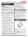
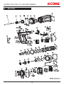
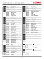
TM Serious Connections GTI-140 Insulation GAS TOOL USER MANUAL TM ICCONS™ GAS TOOL GTI-140 USER MANUAL Masthead Serious Connections Table of Contents Version GTI-140 -R01/2013 Copyright: ICCONS™ Pty Ltd 12-18 Produce Drive, Dandenong South, Victoria , Australia 3175 Passing on and duplication of this document, exploitation and disclosure of its contents are forbidden unless expressly approved. Violations render the offender liable to damages. All rights reserved for the event of patent, utility model or registered design applications. This operating manual has been drawn up with the greatest care. Nevertheless, ICCONS™ Pty Ltd assumes no liability for possible errors in this operating manual and their consequences. Furthermore, no liability is assumed for direct or consequential damages resulting from the improper use of the tool. The national safety and occupational safety regulations and the safety precautions given in this operating manual must be observed when using the tool. 1 Symbols Used In This Operating Manual 3 2 General Safety Instructions 3 2.1 2.2 2.3 2.4 2.5 3 3 4 4 4 Introduction Safety Of The Fastening Tool Safety At Work Safety For Handling Fasteners Safety For Gas Operated Nailer Tool 3 Use of the Fuel cell 5 3.1 3.2 3.3 3.4 Safety for Handling the Fuel Cell Transport Storage First Aid 5 5 5 5 4 Use Of The Battery & Charging System 6 4.1 4.2 4.3 6 6 6 Before Charging Safety For Handling Battery Storage 5 Tool Operation 6 5.1 5.2 5.3 5.4 5.5 5.6 5.7 5.8 5.9 6 7 7 8 8 8 9 9 9 Charging Installing & Removing The Battery Battery Light Indicator Preparing The Fuel Cell Installing & removing Fuel Cell Installing & removing Barrel Loading The Pins Driving The Pins Cleaning the Filter 6 Troubleshooting 10 All product designations and brand names are the property of their owners and are not explicitly marked as such. 6.1 6.2 6.3 6.4 6.5 10 10 11 12 12 Amendments to content reserved. 7 Technical Specification 13 7.1 7.2 7.3 7.4 7.5 7.6 13 13 13 13 13 13 13 2 Battery/Charger Problems Normal Stage of Operation Pre-Combustion / Combustion Stage Power / Exhaust Stage of Operation Returning / Purging stage of Operation Gas Nailer Fuel Cell Fastener AC/DC Adaptor Battery Charger Unit Battery Cell Pack 8 Tool Serial Number 13 9 Parts List 14 10 Declaration Of Conformity 16 11 Copyright 17 12 Disposal 17 13 Warranty 18 TM ICCONS™ GAS TOOL GTI-140 USER MANUAL 1 The ICCONS Pty Ltd Gas Nailer is referred to as “tool” in this general safety instruction. ICCONS Pty Ltd is referred to as “manufacturer” in this general safety instruction. Symbols Used in this Operating Manual WARNING: READ ALL SAFETY WARNINGS AND ALL INSTRUCTIONS 2.1 Introduction TO REDUCE THE RISK OF INJURY, READ THE INSTRUCTION MANUAL BEFORE USE. Only those fasteners which are specified in the operating instructions shall be used in the tool. The tool, the fastener, the fuel cell and the battery specified in the operating instructions are to be considered as one unit safety system. DANGER ! THE TOOL MUST NOT USED IN A COMBUSTIBLE ENVIRONMENT OR CONFINED SPACE. WARNING ! CHECK THE SAFETY YOKE IS FUNCTIONAL ON EVERY OPERATION. It must reliably return to its starting position. - Only spare parts specified by the manufacturer or his authorized representative shall be used in the service or repair of the tool. WARNING ! KEEP TOOL AWAY FROM SMOKE AND FIRE. - Repairs shall be carried out only by the manufacturer or his authorized representative. WEAR EAR PROTECTION - Keep the tool, fasteners, fuel cell, battery and charger out of the reach of children. WEAR EYE PROTECTION 2.2 Safety Of The Fastener Driving Tool - Check prior to each operation that the safety mechanism is functioning properly. Rectify any loose fasteners or defects on the tool before use. - Only use the tool for nailing application for which it was designed. - It is not permitted to make any modification to the tool, fuel cell or battery, other than those specified by the manufacturer. - If the tool is weakened or damaged by: punching or engraving; modification not authorized by the manufacturer; guiding against templates made of hard material; dropping or pushing across the floor; use as a hammer; apply excessive force of any kind; it should be taken to service and inspect by the manufacturer or authorized agents. - Operator should carry out regular USE PROTECTIVE HAND WEAR 2 Serious Connections GENERAL SAFETY INSTRUCTIONS WARNING Read all safety warnings and instructions. Failure to comply with the safety warnings and instructions can result in severe injuries. Keep all safety warnings and instructions for future use. This appliance is not intended for use by person (including children) with reduced physical, sensory and mental capabilities, or lack of experience and knowledge. 3 TM ICCONS™ GAS TOOL GTI-140 USER MANUAL maintenance (cleaning and lubrication) in accordance with the operation manual to keep the tool in good working order. - The fastener driving tool should be serviced properly and at regular intervals in accordance with the operation manual. Serious Connections areas with concealed hazards. This will avoid a hazard caused by free flying fasteners and excessive strain of the tool. Take particular care when nailing close to edges as fasteners can break-out and deflect out of the substrate. - If tool jams or misfires, always remove the battery and fuel cell prior to examination of the tool. If the problem persists stop operating the tool, unload the fasteners, and contact the manufacturer or authorized agents for service. 2.3 Safety At Work WARNING! Always assume the tool is loaded. Never point any tool at yourself or at any other person. - Make sure the workplace is clean and well lit. - Stay alert, watch what are you doing, and use common sense when operating the tool. Do not use tool while tired or under the influence of drugs, alcohol, or medication. - The tool must be carried pointed downward while moving locations. Never carry the tool with your finger on the trigger. - Never press your hand on the front of the tool. The tool must be operated only when it is in contact with the material to be fixed. - The operator must be in a stable position when using the tool. Operate the tool in the manner that should the tool recoil, there is no risk of injury to the operator. - When using the tool, the operator and any bystanders must wear appropriate eye and ear protection. - When not in use, remove the battery, fuel cell and fasteners, return the fastener follower to guide locking position, and return the tool to its carrying case. 2.5 Safety for Gas-operated Nailer Tool - The tool must not be used in a combustible environment. - The tool must be used in well-ventilated areas. Exhaust gases in a confined space can be hazardous. Do not use the tool outside in the rain or where excessive moisture in present. - Keep the tool from heat sources as the pressurized fuel cell could be damaged. - Do not smoke when handling the fuel cell. - Keep away from your face and eyes. Do not inhale its content. - The temperature of the tool may increase depending on the firing frequency. Observe the maximum cycle rates given in the operating instructions. 2.4 Safety for Handling Fasteners - Do not load the fasteners with the trigger and/or work-contacting element pressed. - Ensure that you use the correct length of fastener with the depth adjuster correctly set, so that nails do not protrude when a fixing is made. - Do not drive fasteners on top of other fasteners. - Never drive fasteners into free space or 4 TM ICCONS™ GAS TOOL GTI-140 USER MANUAL 3 Serious Connections - Dispose of only in designated places. - For optimum performance, use before the date indicated at the bottom of the cartridge. Use Of The Fuel Cell DANGER ! KEEP FUEL CELL AWAY FROM SMOKE AND FIRE 3.2 Transport The regulations by transport categories are: - Road/Rail: ADR/RID – UN code 2037 class 2.1 - Sea: IMDG – UN code 2037 class 2.1 EmS F-D, S-U - Air: IATA – UN code 2037 class 2.1 Goods must be accompanied by a transport emergency card for road UN 2037 Transport by post is not permitted. WARNING ! LIQUID GAS CAN CAUSE INJURY IN THE CONTACT WITH THE SKIN OR EYES WARNING ! FUEL CELL CONTENTS ARE EXTREMELY FLAMMABLE WEAR EYE PROTECTION 3.3 Storage - Stores and showrooms must comply with building regulations. All local instructions corresponding to fire regulations must be followed. - Where possible, store fuel at stable temperature in the range: 5 to 25°C. Do not expose to temperatures exceeding 50°C. Do not use a tool that emit flames, sparks or reach high temperatures in the vicinity that fuel cells are stored. - Do not store in designated thoroughfares, hallways or stairwells. - Stores in a well-ventilated area. Fuel cells must not be displayed in shop windows. - Storage with pyrotechnic products is not permitted. USE PROTECTIVE HAND WEAR Introduction The fuel cell is an aerosol product corresponding to the 2008/47/EC regulations. It contains: - Liquefied hydrocarbon gases (Butane & Propane). - Lubricant to help tool work smooth. 3.1 Safety for Handling the Fuel Cell - The fuel cell is always pressurized with propellant to sustain the fuel supply to the metering valve, even if the fuel is used up. Its contents are extremely flammable. The fuel cell is not reusable. Do not attempt to refill. - Do not spray towards a flame or an incandescent body. Keep away from any heat sources and from electrostatic charges. - Do not smoke when handling or loading fuel cells. - Do not expose to temperatures exceeding 50°C. - Store and use the cartridge in a wellventilated area only. Do not inhale. - Do not pierce or burn the cartridge after use. - Keep away from children. 3.4 First Aid - Direct contact with liquid gas may cause burns or frostbite. - In case of inhalation remove the person to fresh air, and encourage breathing. Should the casualty become unconscious, or breathing does not quickly return to normal, summon urgent medical assistance. - If gas gets into the eyes they should be flushed out with copious amounts of water. Skin contaminations should be removed with soapy water. - If symptoms persist, seek medical assistance. 5 TM ICCONS™ GAS TOOL GTI-140 USER MANUAL 4 Serious Connections - Do not short circuit the battery pack. - Do not pierce or open the battery pack. - Do not store the batteries at a temperature above 50°C. - Do not incinerate spent batteries. - Only charge one battery at a time. - Batteries and charging systems must be recycled or taken to a designated disposal area. Use Of The Battery & Charging System Introduction The adaptor, charger and the battery are designed to operate together as one system. Only use the ‘ICCONS Pty Ltd’ Adaptor & ‘ICCONS Pty Ltd’ Charger for charging the ‘ICCONS Pty Ltd’ Batteries. The charging system is intended to be used in covered areas. Do not expose it to rain or to excessive humidity. Do not recharge non-rechargeable batteries. 4.3 Storage - Store the batteries in a cool and dry place. - Over-discharge will degrade the batteries capacity. Fully charged the batteries if stored for a long time. Recharge it in each 3 months can help to compensate the self-discharged and keep the battery in a good condition. - The charging systems should store at a place out of reach of children. Children should be supervised to ensure that they do not play with the appliance. - Always disconnect the batteries with tools or charger while stored. 4.1 Before Charging - Arrange the adaptor output lead appropriately to avoid unnecessary damage, avoid laying output lead across walkway or doorway. - Check the system before use, if cable or plug damaged do not use for charging battery, and replace it immediately. - Keep the charger exhaust area clean and unblock to have the best cooling effect. Use dry cloth to clean the body and the contact of the charger or adaptor while it disconnected with the main power. - Charge the battery in room temperature. If its temperature is less than 5°C or greater than 40°C will degrade the battery charging performance. - If the battery charger abnormally heats up or gives off fumes during charging, disconnect the charger and separate with the battery immediately. - This appliance is not intended for use by person (including children) with reduced physical, sensory and metal capabilities, or lack of experience and knowledge, unless they have been given supervision or instruction concerning use of the appliance by a person responsible for their safety. - Children should be supervised to ensure that they do not play with the appliance. 5 Tool Operation 5.1 Charging Steps: 1. Plug the battery charger into the proper AC voltage source, both green and red light will remain alight. 2. Insert the battery into charger, red light will alight indicating the battery is charging. 3. It takes about 2.5 hours for charging. 4. When fully charged, green light will remain alight. 5. After charging, unplug the charger from 4.2 Safety For Handling Battery 6 TM ICCONS™ GAS TOOL GTI-140 USER MANUAL the power source. • If both lights are blinking in same pace, remove the battery cartridge and plug again. • If this happens continuously, the battery cartridge may be damaged. Consult authorized serviceman for replacement of new battery cartridge. NOTE: • Never attempt to open the charger or battery cartridge. • The battery charger is for charging specific battery pack. Never attempt to charge battery pack from other manufacturer’s battery cartridge. Unsuitable battery cartridges may cause fire that causes injury. • When the battery charger is being used, keep out of direct sunlight. • To get better cooling effect, keep the exhaust area clean. Serious Connections Green LED light blinks every 0.5 sec under working condition. Battery level sufficient for working. Red LED blinks every 4 sec or keep alighted under working condition. Low battery level, need to unplug and recharge immediately. Red LED blinks every second. The tool has entered protection mode. Stop using the tool immediately and consult authorized serviceman for maintenance NOTE: • After using the tool, remove the battery from the tool to prevent the tool from being fired. 5.2 Installing & Removing The Battery Steps: 1. Empty fasteners from the magazine and make sure the trigger is not pulled while installing the battery. 2. To install the battery, insert the battery cartridge until hearing a “click”. 3. Turn and lock the battery to avoid loosen during shooting. 4. To remove the battery, turn to unlock, grip the button at the back of battery cartridge and pull out. 5.3 Battery Light Indicator 7 TM ICCONS™ GAS TOOL GTI-140 USER MANUAL 5.4 Preparing The Fuel Cell Serious Connections 5.5 Installing & Removing Fuel Cell Caution ! • • • Make sure the trigger is not held while inserting fuel cell. Empty fasteners in the magazine before installing fuel cell. Do not press on the surface ground while installing. Steps: 1. Push up and pull to open the fuel door. 2. Insert the fuel cell, direct the jet nozzle into the adaptor. 3. Put the can door over the valve and push it down to latch. 4. For removing fuel cell, reverse the above steps. Caution ! • Never attempt to use fuel cell from other manufacturer. • Do not remove the cap when it is unused. • Never drill a hole on the fuel cell. • Do not inhale the gas. Breathing in the gas could cause sleepiness, dizziness or nausea. • The fuel cell is not refillable, do not attempt to refill the gas. 5.6 Installing & Removing Barrel Steps: First ensure to use the correct colour valve, the colour of the rim for IS140 should be green. Caution ! • Make sure the trigger is not held while inserting barrel. • Do not press on the surface ground while installing. • Do not cover the barrel with your hand while installing. 1. Detach the cap, attach the valve by pushing in the front edge. 2. Pushing the rear edge until it has “clicked”. NOTE: • Make sure the fuel cell valve is attached firmly, if not, gas leakage may occur and create hazards to users and bystanders. Steps: 1. Press down and hold the adapter for barrel. 2. Insert the barrel and release the adapter. 3. Rotate the barrel until the adapter returns to its original position. 4. For removing press and down the adapter and pull the barrel out. 8 TM ICCONS™ GAS TOOL GTI-140 USER MANUAL Serious Connections surface) firmly until you hear the fan motor is working. 3. Pull the trigger, the pins are driven to the object. 4. Release the trigger and lift the tool. 5.7 Loading The Pins 5.9 Cleaning the Filter The filter at the back of the tool acts crucially to suck in air into the chamber. For maintaining the best performance of the tool users should always keep it clean. Caution ! • Make sure the trigger is not held while loading the pins. • Do not press on the surface ground while loading. 1. Unscrew four screws on the back cover 2. Take out the back cover and clean the mesh with brush or air. 3. Put the back cover on the machine and fasten with four screws. Steps: 1. Insert the insulation fastener into the barrel until it reaches the tip of pin guide. 2. For removing the insulation fastener, simply pull the fastener out from the barrel. NOTE: • Do not attempt to use water to clean the mesh. The cover and mesh must be dry when operating the tool. If wet it may easily cause malfunction to the tool. 5.8 Driving The Pins Caution ! • Please READ and UNDERSTAND the section “General Safety Instructions” for personal and working environment safety. • If you spot of any abnormality about the tool, contact nearest authorized serviceman for inspection and repairing. Steps: 1. Press the tool with suitable length of insulation fasteners through the insulation material. 2. Press the Nose of the contact arm against working surface (90° against the 9 TM ICCONS™ GAS TOOL GTI-140 USER MANUAL 6 Troubleshooting WARNING: To reduce the risk of serious personal injury, ALWAYS unload the battery, the pins and fuel cell from the tool before all repairs. Battery is hot. SYMPTOM 1 Battery Cell does not appear to accept charge. Green charger light does not come on after several hours. Services Inoperative indicator lights on charger. Try Battery in tool after 3 hours on charge cycle. If tool functions properly charger lights are not working correctly. Replace charger, or monitor time to ensure Battery Cell has adequate time for recharging. It’s normal for Battery to feel warm after properly charging. Damaged charger. Possible reasons Services Battery damaged or cycle life exhausted. Replace Battery. 6.2 Normal Stage of Operation Discontinue use immediately and unplug from power source. Replace charger and tag or dispose of charger to prevent accidental reuse or connection to power source. SYMPTOM 2 Red and green LEDs on charger are blinking alternately. Possible reasons Remove battery from charger and allow to cool. Inspect battery charger and cartridge. SYMPTOM 3 Red and green LEDs on charger are blinking simultaneously. 6.1 Battery/Charger Problems Possible reasons Serious Connections SYMPTOM 1 Fan does not run. Possible reasons Services Battery is not charged. Charge Battery according to Operating Manual. Battery Terminals or Handle battery contacts are oily, dirty, or corroded. Clean Battery Cell terminals Clean Handle Battery Cell contacts as required. There is electrical short somewhere. The tool must be looked into by Authorized Serviceman. SYMPTOM 2 Fan does not run, or runs slower than normal. Services 10 Possible reasons Services Battery is discharged. Charge Battery Cell. TM ICCONS™ GAS TOOL GTI-140 USER MANUAL SYMPTOM 3 Fan runs intermittently. Serious Connections SYMPTOM 2 Failure to install fasteners to nose piece. Possible reasons Services Possible reasons Services Battery is loose or contacts are bent. Snap battery back into its locked position. Bend contacts back into proper position. Piston positioned wrongly. Return piston to original position according to User Manual. O-Ring is Contact authorized damaged and serviceman for repair. causing leakage of gas. 6.3 Pre-Combustion / Combustion Stage of Operation SYMPTOM 1 Contact Arm does not depress fully, tool does not operate. Possible reasons Services Lockout Bar is stuck in lockout position. Check if there is not enough pins in the channel, load extra pins according to Operating Manual. The nose piece is bent, or the channel is stuck with dirt. Inspect if the nose piece and channel is clean. If it is damaged, consult authorized serviceman for repair and replacement of the parts. Contact authorized serviceman for repair. Valve wave washers lose elasticity. Contact authorized serviceman for repair. SYMPTOM 3 Tool will not cycle - fan runs. Follower holder Slide gently the follower positions wrongly holder to the bottom and at the top of release. the magazine strip. Possible reasons Services Fuel Cell is empty. Replace Fuel Cell. Spark does not occur. Contact authorized serviceman for repair. SYMPTOM 4 Fail to drive fasteners. Cylinder head Contact authorized O-Ring pinched. serviceman for repair. Jammed fasteners. Some dirt on the valve washer inside cylinder. Clear jam according to User Manual. Possible reasons Services Water vapour surrounding spark causing short circuit. Dry the spark area or contact authorized serviceman for repair. Sealing pad damaged. Contact authorized serviceman for repair. Piston guide Contact authorized stuck with dirts. serviceman for repair. 11 TM ICCONS™ GAS TOOL GTI-140 USER MANUAL 6.4 Power / Exhaust Stage of Operation SYMPTOM 4 Unstable performance. SYMPTOM 1 Tool operates properly, but fasteners do not drive fully. Possible reasons Services Battery is discharged. Charge battery. Fuel Cell is low. Replace fuel cell according to User Manual Services Fastener strip may be binding. Use only fasteners meeting designated specifications. Follower holding wrong at the top of the pin strip. Slide follower holder gently to the bottom and release to reset the pin strip in the magazine. Jammed fasteners Clear jam according to User Manual. Possible reasons Services Built-up dirt and debris inside cylinder Contact authorized serviceman for repair. SYMPTOM 5 Diminishing power. SYMPTOM 2 Tool operates, but no fastener is driven. Possible reasons Serious Connections Possible reasons Services Damaged piston or cylinder. Contact authorized serviceman for repair. 6.5 Returning / Purging stage of Operation SYMPTOM 1 Tool operated and drove fastener, but piston did not return to up position. SYMPTOM 3 Operation of the tool is not stable. Possible reasons Services Mushrooming of Piston Tip. Contact authorized serviceman for repair. Possible reasons Services Exhaust ports on Contact authorized the sleeve are serviceman for repair. dirty or clogged Fuel Cell is low. Replace fuel cell according to User Manual. Tool (Sleeve) or O-Rings are dirty. Spark Plug wire Contact authorized is loose. serviceman for repair. Filter element Remove filter element is dirty,causing and clean according to tool to overheat. User Manual. Tool sleeve or O-Rings are dirty. Contact authorized serviceman for repair. SYMPTOM 2 Combustion Chamber does not drop after tool cycles. Contact authorized serviceman for repair. 12 Possible reasons Services Contact arm is bent, or tool is dirty. Clean tool or replace contact arm as require TM ICCONS™ GAS TOOL GTI-140 USER MANUAL 7 The adaptor, charger and the battery are designed to operate together as one system. Technical Specification 7.1 Gas Nailer 7.4 AC/DC Adaptor Model No. GTI-140 Dimensions Length 530 mm Height 120 mm Width 360 mm Weight 4.2 kg Recommended Usage 600/Hr 3,000/Day Vibration The vibration/mechanical impact risk is low, it is the users’ responsibility to ensure that the operators are not put at risk due to environmental and work piece specifications. Model No. BCA1215 BCA1215(ANC) TYPE I BCA1215(EU) TYPE C BCA1215(UK) TYPE G BCA1215(US) TYPE A 7.5 Battery Charger Unit Model No. Input Output Charging Time Battery Type FC165G 165 mm 32 mm 18 bar 700 shots GT-BCU 12V DC 1.5A 7.3V DC 700mA 2.5 Hours ICCONSB6VMH 7.6 Battery Cell Pack Model No. Type Output Capacity Fuel cell contains pre-mixed fuel and lubrication. No extra lubrication required. Warning! Only specified Fuel Cell and Lubricant by ICCONS can be used on the tools, please consult the ICCONS agents or local distributors. 8 GT-BCP Ni-MH 6V DC 1.5Ah, 5 cells Tool Serial Number Located on the tool handle near the track connection. 7.3 Fastener Dimensions Insulation Thickness Pin Head Diameter Pin Length Shank Diameter - AS/NZ - EU - UK - US Input 100-240V ~ 0.6A Max. 50/60Hz Output 12V DC 1.5A 7.2 Fuel Cell Model No. Dimensions Height Diameter Pressure Capacity Serious Connections 25-140 mm Ø6.3 mm 47-52 mm Ø3.65/3.2 mm Applications Insulation Thickness 25-140 mm Only those fasteners which are specified in this specification shall be used in ICCONS Pty Ltd Gas Tools. The ICCONS Pty Ltd Gas Tool and the fasteners specified are to be considered as one unit safety system. 13 YY MM XXXX YY - Year of construction (last two digits) MM - Month of construction XXXX - Tool serial number TM ICCONS™ GAS TOOL GTI-140 USER MANUAL 9 Parts List 14 Serious Connections TM ICCONS™ GAS TOOL GTI-140 USER MANUAL POS. CODE DESCRIPTION CODE DESCRIPTION 1 NB4010 PIN GUIDE 51 NB4ZD0 PISTON WITH RING 2 NB4420 GUIDE SLEEVE 52 NB2550 PISTON RING 53 NB2560 RETAINING RING 54 NB2570 ROUND HEAD SCREW 55 NB2580 COMBUSTION CHAMBER 5 NB4410 POS. Serious Connections NOSE PIECE 10 NB1040 SOCKET SCREW 56 NB2600 AIR DAM 11 NB1050 BUSHING 57 NB2590 U-WIRE 12 NB2060 DUST SHIELD 58 NB2920 PISTON STOP 13 NB1070 SHIELD SPACER 59 NB2930 PISTON STOP RUBBER 14 NB2Z10 HOUSING 15 NB2Z20 HEAD COVER 60 NB2610 HEAD O-RING 16 NB1780 SOCKET SCREW 61 NB1620 BLADE ASSEMBLY 62 NB2630 CYLINDER HEAD 20 NB2Z30 HANDLE 63 NB1650 SPARK PLUG 21 NB2130 FIRING CAM 64 NB2660 FUEL NOZZLE 22 NB1Z40 FUEL DOOR 65 NB1670 MOTOR SLEEVE 23 NB1Z50 BUSHING 66 NB1680 MOTOR BUMPER 67 NB1690 MOTOR 25 NB210B SOCKET SCREW 68 NB1700 MOTOR GUIDE 26 NB1290 METAL WASHER 69 NB1641 CONNECTOR BOARD 27 NB1170 LOCKNUT 70 NB1710 MOTOR HOLDER 28 NB1380 METAL WASHER 71 NB1720 SPRING WASHER 29 NB1370 SOCKET SCREW 72 NB1730 ROUND HEAD SCREW 30 NB2Z60 CONTROL UNIT 90 NB2140 HOOK & TRACK LOCK 31 NB1180 ELECTRODE ASSEMBLY 32 NB1220 TRIGGER SWITCH 33 NB1310 MOTOR SWITCH 34 NB1270 SELF TAP SCREW 35 NB2Z70 TRIGGER WITH SPRING 36 NB1200 TRIGGER SPRING 37 NB1300 SWITCH LEVER 38 NB1260 SWITCH PLATE 39 NB1Z80 BATTERY LOCK 40 NB2430 CAGE 41 NB1440 CAGE SPRING 42 NB2450 RETAINING RING 43 NB1470 WAVE WASHER 44 NB1480 VALVE WASHER 45 NB2Z90 CYLINDER ASSEMBLY 46 NB2520 CYLINDER O-RING 47 NB2460 VALVE COVER 50 NB2530 BUMPER # 10* 16 23* 25* 29 34 54* 72 * # 15 Thread M5 x 25 M5 x 30 M5 x 14 M5 x 16 M4 x 16 Z3 x 9 M5 x 10 M4 x 20 LOCTITE BLUE LOCTITE RED # 27 Nut M4 # 23 26 28 71 Washer 12mm 10mm 9mm M4 TM ICCONS™ GAS TOOL GTI-140 USER MANUAL 10 Declaration Of Conformity With regard to the Machinery Directive 2006/42/EC The manufacturer/ distributor: ICCONS™ Pty Ltd 12-18 Produce Drive, Dandenong South Victoria, 3175, Australia Declare under our sole responsibility that the products: A. Gas powered nailer with removable magazine with reference to model GTI-140, conforms to the following standards or normative documents: 1. EN 792-13:2000+A1:2008 Handheld non-electric power tools – Safety requirements. Part 13: Fastener driving tools. Having been examined to the requirements of the Machinery Directives 2006/42/EC by: Safenet Limited (Notification#: 1674) c/o Denford Garage, Denford, Kettering Northamptonshire, NN14 2EQ, UK Issued the EC examination certificate: TBA with available technical file copy for the equipment. Serious Connections Intertek Testing Services Hong Kong Ltd. 2/F., Garment Centre, 576 Castle Peak Road, Kowloon, Hong Kong Issued the test verification of conformity number: 12100822HKG-002R1 2. EN 60335-2-29:2002+A1:2004+A2:2009 EN 60335-1:2010 Having been examined to the requirements of the Low Voltage Directive 2006/95/EC by: Intertek Testing Services Hong Kong Ltd. 2/F., Garment Centre, 576 Castle Peak Road, Kowloon, Hong Kong Issued the test verification of conformity number: 13070126HKG-003, 13070126HKG-004 3. EPS IM 278/2009 Having been examined to the requirements of the Energy related Products Directive 2009/125/EC by: Intertek Testing Services Hong Kong Ltd. 2/F., Garment Centre, 576 Castle Peak Road, Kowloon, Hong Kong Issued the test verification of conformity number: 1307128HKG-001 B. AC/DC adaptor, charger & battery with reference to model: GT-BCU, GT-BCP, BCA1215, conforms to the following standards or normative documents: 1. EN 55014-1:2006+A1+A2, EN 55014-2:1997+A1+A2, EN 61000-32:2006+A1+A2, EN 61000-3-3:2008 Having been examined to the requirements of the Electromagnetic Compatibility Directive 2004/108/EC by: 16 TM ICCONS™ GAS TOOL GTI-140 USER MANUAL Serious Connections 11 Copyright 12 Disposal Copyright: ICCONS™ Pty Ltd 12-18 Produce Drive, Dandenong South Victoria, 3175, Australia Recycle the tool and its packaging in an environmentally friendly manner in accordance with the recycling regulations applicable in your country. Passing on and duplication of this document, exploitation and disclosure of its contents are forbidden unless expressly approved. Violations render the offender liable to damages. All rights reserved for the event of patent, utility model or registered design applications. Separate collection. Local regulations may provide for separate collection of electrical products from the household, at municipal waste sites or by the retailer when you purchase the new product. This operating manual has been drawn up with the greatest care. Nevertheless, ICCONS™ Pty Ltd assumes no liability for possible errors in this operating manual and their consequences. Furthermore, no liability is assumed for direct or consequential damages resulting from the improper use of the tool. Separate collection of packaging and failed rechargeable battery in accordance with the recycling regulations applicable in your country. The national safety and occupational safety regulations and the safety precautions given in this operating manual must be observed when using the tool. All product designations and brand names are the property of their owners and are not explicitly marked as such. Amendments to content reserved. 17 TM ICCONS™ GAS TOOL GTI-140 USER MANUAL Serious Connections 13 Warranty ICCONS™ Pty Ltd warrants the original purchaser of the GTI140 against defective workmanship and faulty materials for 12 months from date of purchase. It is a condition of the warranty period that; • Proof of original purchase and ownership, including address and phone number must be provided. • The GTI140 has not been subjected to misuse, (beyond the recommendations or limitations specified and as outlined in the ICCONS™ GTI140 User manual), neglect or been damaged, modified or repaired without the approval of ICCONS™. • The tool is presented on return in a condition that displays it has been cleaned and serviced as outlined in the ICCONS™ GTI140 User manual. • The Repairs to the tool are not required as a result of normal wear and tear (eg: Piston / Piston Rings ) WHERE LAWFUL, UNDER NO CIRCUMSTANCES SHALL ICCONS™ PTY LTD BE LIABLE FOR INCIDENTAL, CONSEQUENTIAL, SPECIAL DAMAGES OR DIRECT OR INDIRECT LOSS OF ANY KIND, INCLUDING BUT NOT LIMITED TO BODILY INJURY, DEATH OR PROPERTY DAMAGE. ICCONS ENTIRE LIABILITY IS LIMITED TO THE PURCHASE PRICE OF THIS PRODUCT. If you wish to make a warranty claim, then the tool or part must be returned to ICCONS™ Pty Ltd at the owner’s expense. ICCONS™ will inspect the returned tool/parts, and at its own option may replace the tool/ parts and return it to the owner at its own cost if deemed to fall within the scope of the warranty conditions. ICCONS™ Pty Ltd cannot be held responsible for any repair other than those carried out by it or one of its Authorised Service Agents. IMPORTANT NOTE FOR AUSTRALIAN CONSUMERS: Our goods come with guarantees that cannot be excluded under the Australian Consumer Law. You are entitled to a replacement or refund for a major failure and for compensation for any other reasonably foreseeable loss or damage. You are also entitled to have the goods repaired or replaced if the goods fail to be of acceptable quality and the failure does not amount to a major failure. PLEASE RETAIN A COPY OF THE TAX INVOICE FOR YOUR WARRANTY. OWNERS COPY AND RECORD (original purchase receipt is still required for claims) SERIAL No: DATE PURCHASED: DISTRIBUTOR / DEALERS NAME: DEALER ADDRESS: 18 TM ICCONS™ GAS TOOL GTI-140 USER MANUAL Serious Connections TM Serious Connections ICCONS Pty Ltd 12-18 Produce Drive Dandenong South Victoria, 3175 Australia Tel: +61 (03) 9706 4344 Fax: +61 (03) Email:[email protected] Web:www.iccons.com.au This manual must be observed when using the tool. All product designations and brand names are the property of their owners and are not explicitly marked as such. Amendments to content reserved. 19